1
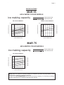
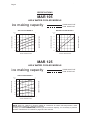
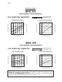
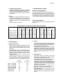
Page 1
Page 1
SERVICE MANUAL
MAR 55
MAR 75
MAR 105
MAR 125
MAR 205
MAR 305
R 134 A / R 404 A VERSION
Scale ice machines
MS 1000.66 - REV. 06/2000
Page 2
Page 2
FOREWORD
The "MAR" ice makers make flake ice of "scale"
type which is flat, hard dry and sub-cooled, giving
to it an exceptional staying power for multiple
chilling operations.
The design simplicity accounts for the confidence
in MAR scale ice machines. Their ice making
system has only one sealed moving part, resulting
in a minimum of maintenance operations for
continuous reliable machine service.
Ice is discharges through a large opening on the
back of unit cabinet, when mounted on top of the
refrigerated room, ice is gravity fed to storage
area.
Rugged, solid, heavy duty, the stainless steel
MAR cabinet has removable panels that facilitate the accessibility to mechanical and electrical
parts. A console panel with lights monitoring
water flow pressure, and temperature operating
refrigerant pressure and motors overloading
foreworn the system malfunction before becoming
major trouble.
We suggest you to take time now to read this
manual which contains a lot of valuable
informations on the MAR ice making system.
If you have any further queries regarding the care
or operation of the machine, please contact:
®®
ICE
SYSTEMS
SCOTSMAN - EUROPE - FRIMONT SPA
Via Puccini, 22 - 20010 Bettolino di Pogliano (Milano) Italy
Tel. +39-02-93960.1 (Aut. Sel.)- Telefax +39-02-93550500
Direct Line to Service & Parts:
Phone +39-0331-589305 - Fax +39-0331-584306
Website: www.scotsman-ice.com
E-Mail: [email protected]
NOTE: Whenever writing please state model no. and serial no. of the machine
Page 3
Page 3
TABLE OF
CONTENTS
Section I
Section II
Section III
Section IV
Section V
Section VI
Section VII
Foreword
Table of contents
Specifications - MAR 55 - 75 - 105 - 125
Specifications - MAR 205 - 305
Remote cond.
GENERAL INFORMATIONS & INSTALLATIONS
Description
Unpacking & Inspection
Location & Levelling
Electrical connections
Water supply & Drain connections
Remote air cooled condenser installation
Ice level control
Ice chute
Final check list
Unit installation practice
Remote condenser installation practice
OPERATING INSTRUCTIONS
Start-up
Water & Refrigerant circuit
PRINCIPLES OF OPERAZION - HOW IT WORKS
Ice maker
Electrical / Refrigeration
Refrigerant charge
Mechanicals
ADJUSTMENT & REMOVAL & REPLACEMENT
PROCEDURES
Water regulator assy
Automatic expansion valve
Water level
V Belt change on pulley
Compressor replacement
Water cooled condens. replacement
Water regulator replacement
Drier replacement
Drive motor replacement
Gear Box replacement
Fiber key replacement
page
2
3
4-5-6
7-8
9
10
10
11
12
12
13
14
15
15
15-16
17
18
19
20
21-22-23-24
24
24
25
25
25
25
26
26
26
27
28
28
28
MAINTENANCE & CLEANING INSTRUCTIONS
General
Ice maker
Cleaning instruction
29
29
29-30
SERVICE DIAGNOSIS
Ice making - Refrigerant system
31-32
WIRING DIAGRAMS
MAR 55 - Wiring diagram
MAR 75 - 105 - 125 - Wiring diagram
MAR 205 - Wiring diagram
MAR 305 RC - Wiring diagram
MAR 55 - Functional electric diagram
MAR 75 - 105 - 125 - Functional electric diagram
MAR 205 A/C - Functional electric diagram
MAR 305 RC - Functional electric diagram
33
34
35
36
37
38
39
40
41
Page 4
Page 4
SPECIFICATIONS
MAR 55
AIR & WATER COOLED MODELS
ice making capacity
THICK SCALE ICE
THIN SCALE ICE
WATER COOLED MODELS
Kg./24 h
500
21
400
10
21
350
32
32
38
38
300
250
AMBIENT TEMPERATURE
ICE PRODUCED PER 24 HRS.
10
450
200
ICE PRODUCED PER 24 HRS.
o°C
o°C
450
DE 10 A' 38
Kg./24 h
500
400
350
300
250
200
38
32
27
21
15
10
5
°C
38
WATER TEMPERATURE
32
27
21
15
10
5
WATER TEMPERATURE
MAR 75
AIR & WATER COOLED MODELS
ice making capacity
THICK SCALE ICE
THIN SCALE ICE
AIR COOLED MODELS
o°C
10
AMBIENT TEMPERATURE
ICE PRODUCED PER 24 HRS.
Kg./24 h
540
500
460
21
32
420
38
380
340
300
38
32
27
21
15
10
5
°C
WATER TEMPERATURE
NOTE. Daily ice capacity is directly related to condenser air water inlet temperature, water
temperature to make ice - and age of machine.
To keep your SCOTSMAN MAR performing at is maximum capacity, it is necessary to perform
periodic maintenance as outlined on page 29 of this manual.
°C
AMBIENT TEMPERATURE
AIR COOLED MODELS
Page 5
Page 5
SPECIFICATIONS
MAR 105
AIR & WATER COOLED MODELS
ice making capacity
THICK SCALE ICE
THIN SCALE ICE
WATER COOLED MODELS
o°C
o°C
DE 10 A' 38
Kg./24 h
750
Kg./24 h
800
21
650
32
600
38
550
500
ICE PRODUCED PER 24 HRS.
AMBIENT TEMPERATURE
ICE PRODUCED PER 24 HRS.
10
700
750
AMBIENT TEMPERATURE
AIR COOLED MODELS
700
650
600
550
500
450
38
32
27
21
15
10
5
°C
38
32
27
21
15
10
5
°C
WATER TEMPERATURE
WATER TEMPERATURE
MAR 125
AIR & WATER COOLED MODELS
ice making capacity
THICK SCALE ICE
THIN SCALE ICE
AIR COOLED MODELS
o°C
10
AMBIENT TEMPERATURE
ICE PRODUCED PER 24 HRS.
Kg./24 h
1000
950
21
900
850
32
750
38
650
600
38
32
27
21
°C
WATER TEMPERATURE
NOTE. Daily ice capacity is directly related to condenser air water inlet temperature, water
temperature to make ice - and age of machine.
To keep your SCOTSMAN MAR performing at is maximum capacity, it is necessary to perform
periodic maintenance as outlined on page 29 of this manual.
Page 6
Page 6
MAR 55-75-105-125 - SPECIFICATIONS
62
2 29/64"
175
6 57/64"
MODELS
MAR 55 AS
MAR 55 WS
MAR 75 AS
MAR 75 WS
MAR 105 AS
MAR 105 WS
MAR 125 AS
MAR 125 WS
Cond.
Unit
Air
Water
Air
Water
Air
Water
Air
Water
Water req. (l/h)
Compr.
(HP) * Cond.
Prod.
2
2
2.5
2.5
4
4
4.5
4.5
225
300
480
BASIC ELECTRICALS: 400/50/3N
* at 21 °C amb. / 15 °C water temp.
16
16
21
21
30
30
41
41
Power
(KW)
Minimum
wire size (mm)
2.2
2.2
2.5
2.5
3.5
3.5
4.5
4.5
5 x 1.5
5 x 1.5
5 x 1.5
5 x 1.5
5 x 1.5
5 x 1.5
5 x 1.5
5 x 1.5
Shipping weight
Total Amps.
Finish
400 V
2.7
2.7
2.7
2.7
5
5
6.5
6.5
Stainless
Steel
Stainless
Steel
Stainless
Steel
Stainless
Steel
kg.
lbs.
194
174
204
201
221
217
226
222
427
383
450
442
487
417
497
488
Page 7
Page 7
SPECIFICATIONS
MAR 205
AIR & WATER COOLED MODELS
ice making capacity
THICK SCALE ICE
THIN SCALE ICE
WATER COOLED MACHINES
°C
10
21
32
21
38
32
1500
38
1400
1300
1200
1100
o°C
DE 10 A' 38
ICE PRODUCED PER 24 HRS.
10
1600
ICE PRODUCED PER 24 HRS.
Kg./24 h
1900
AMBIENT TEMPERATURE
Kg./24 h
1700
1800
AMBIENT TEMPERATURE
AIR COOLED MACHINES
1700
1600
1500
1400
1300
38
32
27
21
15
10
°C
5
38
WATER TEMPERATURE
32
27
21
15
10
°C
5
WATER TEMPERATURE
MAR 305
AIR & WATER COOLED MODELS
ice making capacity
WATER COOLED MACHINES
°C
21
2200
32
10
2000
21
1800
32
38
38
1600
1400
o°C
2600
DE 10 A' 38
10
2400
ICE PRODUCED PER 24 HRS.
Kg./24 h
2800
AMBIENT TEMPERATURE
ICE PRODUCED PER 24 HRS.
Kg./24 h
2600
2400
2200
2000
1800
1600
38
32
27
21
15
10
WATER TEMPERATURE
5
°C
38
32
27
21
15
10
5
WATER TEMPERATURE
NOTE. Daily ice capacity is directly related to condenser air water inlet temperature, water
temperature to make ice - and age of machine.
To keep your SCOTSMAN MAR performing at is maximum capacity, it is necessary to perform
periodic maintenance as outlined on page 29 of this manual.
°C
AMBIENT TEMPERATURE
AIR COOLED MACHINES
THICK SCALE ICE
THIN SCALE ICE
Page 8
Page 8
MAR 205-305 - SPECIFICATIONS
210
8 17/64"
MODELS
Cond.
Unit
MAR 205 AS
Air
MAR 205 WS Water
MAR 305 AS
Air
MAR 305 WS Water
Water req. (l/h)
Compr.
(HP) * Cond.
Prod.
5
5
15
15
1200
1600
BASIC ELECTRICALS: 400/50/3N
* at 21 °C amb. / 15 °C water temp.
69
72
88
94
Power
(KW)
Minimum
wire size (mm)
7
7
10
10
5 x 2.5
5 x 2.5
5x4
5x4
Shipping weight
Total Amps.
Finish
400 V
17
10
20
20
Stainless
Steel
Stainless
Steel
kg.
lbs.
374
369
383
413
824
813
844
910
Page 9
Page 9
MAR 305 REMOTE CONDENSER
TECHNICAL SPECIFICATIONS
CONDENSER CAPACITY
FAN MOTOR
AIR FLOW
16200 Kcal/h
230 V - 0.7 A
4 x 1200 m3/h
NOTE. MAR 305 is not for out door installation. Fan motors are not weather proof.
Page 10
Page 10
SECTION I
GENERAL INFORMATION & INSTALLATION
1. DESCRIPTION
An attractive compact cabinet of stainless steel
with control panel lights on the front. All panels
are removable to allow easy access to electrical
and mechanical components for cleaning and
maintenance.
Sealed Refrigeration System
To provide quite efficient operation of the ice
maker, the compressor is mounted on rubber
cushions. The water cooled models have a tube
within tube condenser with water regulation valve for correct condensing water flow. The air
cooled models, except the MAR 305 have a built
in condenser in copper and aluminium with the
fan motor controlled by pressure control. The
evaporator drum is powered by a separate drive
motor connected by a V-belt and pulley system to
a double gear box. The refrigerant used is R 404a
controlled by automatic expansion valve.
Storage Bin or Ice Room
Since the MAR Flaker is a continuous flow type
ice maker and does not have its own attached
storage bin, it is necessary to use an auxiliary bin
or a pre-fabricated ice room for appropriate ice
storage.
Ice storage situations are of two kinds:
a) Short term storage
b) Extended terms storage
Being, as stated, scale ice made by MAR
machines flat, dry and subcooled, therefore with
the tendency to stick toghether, particular
attention is required for proper ice storage
conditions for better ice handling. An insulated
ice storage bin or rooms is always required, then
according to ice end use application, this can be
refrigerated on non-refrigerated.
Also a weight volume ratio of 2,1 cu. mt. per
ton, must be taken into consideration for correct
ice storage.
a) Non-refrigerated room for short term
storage.
The scale ice is produced continuously for 24
hours per day, whereas the use period is
generally for no longer than 8 hours per day.
Therefore storage facilities should be provided
to accomodate a minimum of 16 hours of
production, this means that every scale ice
machine must be installed with a properly
insulated storage room which should have a
minimum capacity of 2/3 the daily ice
production.
With a well insulated room and duly subcooled
scale ice, the limited losses of heat throught
the walls of a properly designed room with
adequate arrangements, are largely offset,
and excess melting will not occur. In most
situations where whole quantity of ice produced
is being used on a daily basis, it is not necessary
to provide cooling for the ice storage room.
b) Refrigerated room for extended storage
and long distance conveying.
When scale ice is to be transported at a
considerable distance, such as aboard fishing
vessels, or in locations with normal ambient
temperatures conditions, or when used in
industrial plants where demand is intermittent,
its subcooling power must be absolutely
preserved in the storage bin by a proper
cooling system keeping air temperature at a
pre-established and constant value. The ideal
ice storage room is the type with mechanically
refrigerated jacket space surrounding the ice
bin. Good practice calls for an ice storage
capacity of about two times the daily ice
machines production with an inside temperature of -6°C minimum (20°F).
2. UNPACKING AND INSPECTION
1. Call your authorized SCOTSMAN Distributor
od Dealer for proper installation.
2. Visually inspect the exterior of the shipping
container and skid and any severe damage
noted should be reported to the delivering
carrier; and a concealed damage claim filled
subject to internal inspection, with carrier
representative present.
3. Remove the packing and remove the shipping
bolts and the shipping base or skid.
4. When necessary, install the leg levellers in
the cabinet base sockets; then, raise the
cabinet to the upright position.
5. Remove screws and shipping tapes and all
doors and service panels from the cabinet and
inspect for any concealed damage.
Notify carrier of any concealed damage claims
as stated in step 2 above.
6. Remove all internal support packing, tape
and wires in machinery compartment.
7. Check that refrigerant lines do not rub or
touch lines or surfaces and that fan blades, if
any, moves freely.
8. Check that compressor is snug on all mounting
pads.
9. Use clean damp cloth or disposable paper
wiper to wipe clean the exterior surface of the
cabinet.
Page 11
Page 11
10. See DATAPLATE on the cabinet base and
check that the location source voltage
corresponds with the voltage specified on
the dataplate.
CONDENSING AIR FLOW SCHEMATIC
MAR 105-125
MAR 205
CAUTION - Unproper voltage supplied to
the icemaker will void your parts
replacement program.
MAR 55-75
MAR 55-75
SIDE
11. Remove the Manufacturer's registration Card
from its envelope and fill in all spaces
including: Model Number and serial Number
taken from the aluminium plate located on
the front of the Chassis base, with Front
Panel removed.
Forward the completed, self addressed,
registration card to the Scotsman Europe
Frimont Factory.
MAR 105-125
MAR 205
3. LOCATION AND LEVELLING
WARNING - The MAR Flakers are NOT
designed for outdoors installation where
air temperature are below 5°C (40°F) or
above 40°C (100°F) and the water temperature is below 5°C (40°F) or above 40°C
(100°F).
Extended periods of operation at
temperatures exceeding these limitations
will constitute misuse, under the terms of
the SCOTSMAN Manufacturer's limited
warranty coverage.
1. Stands - A special stands should be built if
the machine is located beside the bin.
Care should be exercised in making the
stand strong enough to support the weight.
In designing the stand plan for the servicing
of the machine from front, top and sides.
It is also possible to locate the machine on
top of the bin. Care should be used in selecting
a bin that has been specially reinforced.
Standard bins are usually not sufficiently
reinforced for this purpose. An unsteady
platform will cause excessive vibration.
Specially built bins can provide proper support
and allow for a servicing platform.
WARNING - Air Cooled version of MAR
75, MAR 105, MAR 125 and MAR 205 have
the condensing air exhaust throughout
the lower rear area (ice spout side)
therefore it is necessary to avoid to
position the ice maker with the rear side
against any sort of wall that will prevent
proper warm air dissipation.They must
have on their rear side an air gap of 200 m/
m. MAR 55 has the air cooled condenser
on the right side while MAR 305 has a separate remote air cooled condenser. (See
instructions for remote condenser at 6).
2. Erection - For elevations in excess of four
feet or in close quarters, chain falls of fork lift
truck should be used. For location under four
feet, the use of skid boards and rollers is practical.
3. Machine Site - When selecting the permanent
location of air cooled machines, consideration
must be given to volume size of the room and to
ventilation facilities for easy heat removal around
the machine.
In doing this it worths to take on account that:
– MAR 55 AS - has a condenser heat rejection
of 3000 Kcal/hr and fan motor draws air for
1200 m3/h.
– MAR 75 AS - has a condenser heat rejection
of 4900 Kcal/hr and fan motor draws air for
1200 m3/h.
– MAR 105 AS - has a condenser heat rejection
of 7500 Kcal/hr and the two fan motors draw
air for 1200 m3/h each.
– MAR 125 AS - has a condenser heat rejection
of 9750 Kcal/hr and the two fan motors draw air
for 1200 m3/h each.
– MAR 205 AS - has a condenser heat rejection
of 11000 Kcal/hr and the two fan motors draw
air for 2000 m3/h each.
– MAR 305 AS - has a condenser heat rejection
of 16200 Kcal/hr and the four fan motor draw
air for 1200 m3/h each correspondind to
4800 m3/h in total.
4. Position the MAR in the selected permanent
location level the cabinet on both the left-to-right
and front-to-rear directions. The levelling legs
can be adjusted with an opened wrench.
(See unit layout and dimensions at page 20).
Page 12
4. ELECTRICAL CONNECTIONS
The machine has been wired ready for electric
connections. See nameplate for current
requirements to determine wire size to be used
for electrical hook-up. The MAR flaker requires a
solid earth ground wire. See wiring diagram.
Be certain the unit is connected to its own electrical
circuit and individually fused.
The maximum allowable voltage variation, should
not exceed ten percent of the nameplate rating,
even under starting conditions.
Low voltages can cause erratic operation and
may be responsible for serious damage to the
overload switch and motor windings.
All external wiring should conform to the National,
State and local electrical permit and services of
a licensed electrician will be required.
WARNING - The compressor is equipped
with a crankcase heater which has to be
energized even when the ice maker is
switched-off. So, make sure to connect
the unit with the compressor crankcase
heater constantly energized. After long
inoperative periods remember to give
current to the heater 4 hours before the
ice-maker start-up.
Fuse protection of the unit should be made as
follows:
MAR 55-75-105-125 - 3x16 Amps/400V
MAR 205
- 3x24 Amps/400V
MAR 305
- 3x32 Amps/400V
WARNING - The evaporator drum drive
motor is threephase so, at the unit startup,
care must be taken to ensure of the correct
rotation direction of drum. In case of wrong
roration interchange the phases by
interchanging the lead wire connections
of main cord.
5. WATER SUPPLY AND DRAIN
CONNECTIONS
Separate water supplies are recommended.
A. Evaporator or ice making supply water should
be run through a hand shut-off valve before
entering unit. Evaporator supply water
connection has a 3/4" male pipe fitting. This
line also has factory installed water strainer
internally mounted. Incoming water goes
through the float reservoir and then to the
drum reservoir.
Connect to a good cold water supply with
minimum 1/2 O.D. line. A check valve on this
line will be required in some cases depending
on local plumbing codes. The recommended
minimum water pressure is 1 bar (14 Psi). Do
not operate this unit with fresh water supply
below 1 bar (14 Psi). Maximum water pressure
5 bar (70 Psi).
B. The condenser water supply line connects to
the following fitting sizes:
MAR 55 - 75
3/4" gas male
MAR 105 - 125 12 mm O.D. fitting
MAR 205
20 mm 0.D. fitting
MAR 305
25 mm
Page 12
Water supply line size must be adequate to
water flow which, at 15°C temperature water, is:
225 lt/hr for MAR 55
300 lt/hr for MAR 75
480 lt/hr for MAR 105
lt/hr for MAR 125
1200 lt/hr for MAR 205
1600 lt/hr for MAR 305
Incoming water goes throughout the water
regulating valve first and then to the water
cooled condenser. Observe arrow on water
regulating valve. Water supply must be installed
to conform with local code. In some case a
licensed plumber and/or a plumbing permit will
be required.
Water Quality
Water quality is a factor of extreme importance
for good operation of MAR machine. Water
shouldn't be too hard neither too soft.
Hard water will tend to create mineral deposits in
water reservoir, evaporator drum and scraping
blade, rendering rough the chute surface which
prevents ice scales from sliding properly into ice
channel.
On the contrary, water too soft, (de-mineralized)
will cause the ice skin to stick excessively on
drum surface rendering difficult the scraping
operation of same.
The ideal water should have a total hardness
of about 15-20 french degrees.
Precaution Against Water Frost
Like for any other ice maker all necessary
measures must be taken when the cold season
is approaching to protect the water supply line
and the MAR water system against winter
freezing. If cooling tower is used several
precautions should be observed, too.
1. Leave water regulating valve in the system.
2. Separate the make-up water for the reservoir
from the tower water.
3. Use 3/4" tower water lines or larger, depending
on the lenght of run. Over 30 feet, use 1" O.D.
lines.
4. NOTICE: a cooling tower can freeze in the
winter time and the MAR flaker will be in
operation 12 months per year. An indoor tower
and pump can be used with outdoors air ducted
in and out if the fan cycles on water temperature to prevent freezing. An indoor sump can
be used. An auxiliary tower and city-water
hook-up will prove satisfactorily in some
climates. Fresh water in the winter and tower
water during the summer. Consult your tower
and pump manufacturers for proper sizing. In
no event should less than a Nominal 3 to 4 tons
tower, or less than 3/4 HP high pressure tower,
or less than 3/4 HP high pressure tower pump
be used.
C. Drain (When not re-used).
The recommenden tubes for the condenser
waste line are:
- MAR 55-75 - 3/4" GAS female fitting.
- MAR 105-125 - 12 mm I.D.
- MAR 205-305 - 25 mm I.D.
Page 13
Page 13
Water drip tray drain line is 21 m/m I.D. Tube
to be connected with clamp to a 21 m/m hose
barbed fitting for all models.
Waste water line must run to an open trapped
vented drain. If drain is a long run, allow a pitch
of 3 cm per meter.
6. REMOTE AIR-COOLED CONDENSER
AND PRECHARGED REFRIGERANT
LINES INSTALLATION (MAR 305 ONLY)
Use the following for planning the placement of
the condenser relative to the ice machine
Remote
Condenser
Located ABOVE
Ice Machine
Condenser
Distance &
Location
Schematic
Max 3 m
Max 1 m
Remote
Condenser
Located BELOW
Ice Machine
Location Limits - condenser location must
not exceed ANY of the following limits:
• Maximum rise from the ice machine to the
condenser is 3 physical meters
• Maximum drop from the ice machine to the
condenser is 1 physical meter
• Physical line set maximum length is 6 meters
• Line set length maximum is 9 meters.
Calculation Formula:
• Drop = dd x 6.6 (dd = distance in meters)
• Rise = rd x 1.7 (rd = distance in meters)
• Horizontal Run = hd x 1 (hd = distance in meters)
• Calculation: Drop(s) + Rise(s) + Horizontal
Run = dd+rd+hd = Calculated Line Length.
Configurations that do NOT meet these
requirements must receive prior written
authorization from Scotsman.
Do NOT:
• Route a line set that rises, then falls, then rises.
• Route a line set that falls, then rises, then falls.
Calculation Example 1:
The condenser is to be located 0.9 meter below
the ice machine and then 3 meters away horizontally.
0.9 mt x 6.6 = 5.94 + 3 = 8.94. This location would
be acceptable.
Calculation Example 2:
The condenser is to be located 4 meters above
and then 3 meters away horizontally.
4 x 1.7 = 6.8 6.8+3 = 9.8. 9.8 is greater than
the 9 maximum and is NOT acceptable.
Operating a machine with an unacceptable
configurationg will void the refrigeration
system warranty.
In a crate, separated by the unit crate are packed:
1. The air-cooled condenser mounted on the
platform base with the electrical junction box,
condenser shround, fan motors, fan protection
grid, fan motor speed, control and the
refrigerant lines connection couplings.
2. One set of pre-charged refrigerant line with
connection couplings on both ends of following
variety. Liquid I.D. 12 m/m - Gas I.D. 22 m/m
- 6 mts length.
The pre-charged refrigerant lines, 6 meters long,
are equipped with self-sealing coupling
connections and can be connected or disconnect
few times without loosing the refrigerant charge.
The electric cord line, approx. 6 meters long,
located on the left side of the unit has to be
connected to the condenser junction box
terminals.
The condenser fan motors are originally wired for
230 V single phase and have the following
specifications:
RPM 1300 (1559)
WATTS 4x70
AMPS 4x0,7
They operate at 230 V 50 Hz and are controlled
by two pressure controls which are connected to
the system high side.
The fan controls are set to cut-out and cut-in the
fan motor so as to maintain the Hi pressure
between 15 and 17 bar.
A. Location consideration:
1. Limit to 6 meters the lenght of the precharged
refrigerant lines from the ice-maker to the
remote condenser.
2. Maximum vertical rise of 3 meters between
the ice maker and the remote condenser.
3. Best available location, protected from the
extremes of dirt, dust, rain, sun and wind.
B. Unpacking and inspection:
1. Visually inspect the exterior of the shipping
container and any severe damage noted,
should be reported to delivering carrier; and a
concealed damage claim filled subject to
internal inspection with carrier representative
present.
2. Uncrate the remote condenser and precharged refrigerant lines and inspect for any
concealed damage claims, as stated in step 1
above.
3. Check that the pre-charged refrigerant lines
are intact, not kinked, and that there is no
sealed puncture or loss or refrigerant.
C. Remote condenser - Wall attachment
1. Install and attach the remote condenser to the
wall of the building, using the methods and
practices of building standards that conforms
to and meets the local building code
requirements in your area.
Page 14
Page 14
2. Removal junction box cover from remote
condenser and connect the electrical power
lines coming from the unit to the wires of the
fan motors by means of the connecting
terminal board placed into the junction box
following the wires color fitted on the same.
3. Spiral the excess lenght of the precharged
refrigerant lines in the best selected inside
location and in a manner that prevents
refrigerant trapping.
D. Pre-charged refrigerant lines
1. The set of pre-charged refrigerant lines
consists of a self-sealing liquid line and a selfsealing discharge line.
One coupling on each line is fitted with a
Schrader valve, which provides the
servicemen with access for refrigerant
evacuation through tubes, refrigerant charging
and service gauges application when
necessary.
2. When possible, route the maximum lenght of
the pre-charged refrigerant lines inside the
building, with the minimum lenght outside, to
prevent vandalism and to minimize the
condenser effect that exposed lines can produce in cold weather.
Insulate lines that be exposed to outside
temperatures that will be below freezing, for
extended periods of time.
CAUTION - Each coupling on the set of
pre-charged refrigerant lines, the
refrigerant fittings on the remote
condenser and on the icemaker chassis
are self-sealing and should be tightened
1/4 turn more than snug tight.
ALWAYS USE TWO WRENCHES WHEN
TIGHTENING THESE FITTINGS ONE AS A
BACKUP WRENCH TO PREVENT
TWISTING OF TUBING AND POSSIBLE
KINKING OR LINE RUPTURE.
3. Connect the small dia refrigerant line coupling
to the unit fitting labelled "LIQUID" on the right
side of the icemaker chassis.
4. Connect the large dia refrigerant line coupling
to the unit fitting labelled "GAS" on the righ
side of the icemaker chassis.
5. Connect the small dia refrigerant line coupling
with Schrader valve to the condenser fitting
labelled "LIQUID".
6. Connect the large dia refrigerant line coupling
with Schrader valve to the condenser fitting
labelled "GAS".
E. Excess lenght of pre-charged refrigerant lines;
at installations where the icemaker chassisto-remote condenser refrigerant line path is
substantially less than the lenght of precharged refrigerant lines to be installed, route
and dress the excess refrigerant line as
follows.
1. Follow straight line routing when possible.
2. Retain excess pre-charged refrigerant line
inside the building.
CAUTION - DO NOT kink or crimp the
refrigerant lines.
DO NOT bend excess refrigerant lines in
a vertical loop (s), which allow trapping of
refrigerant in LOW sections during OFF
time.
Bend and shape excess refrigerant lines
in VERTICAL spirals, not HORIZONTAL
spirals. See Figure above.
7. ICE LEVEL CONTROL
The MAR flake ice system are equipped with and
adjustable thermostatic control that cutsoff ice
making operation when its sensing bulb gets in
contact with the ice deposited in the storage bin.
The temperature range dial goes from +10°C to
-35°C and its long capillary (3.5 m.) attaching the
liquid filled bulb, should be conveniently positioned
in the storage room at the desired height by
holding it with an appropriate bracket to be
arranged in accordance with the location
possibilities. These controls may or may not be
used, it depends of storage room arrangement
and its inner temperature that must be higher,
anyway, to that of the ice produced.
In case of a prevailing low themperature (below
-20°C) created by the sub-cooled ice that is
staging above the ice level, which will prevent a
positive function of the ice level thermostatic
control, the thermostatic sensing bulb must be
removed from the storage room.
The MAR ice system are also equipped with a
timer which allows to present the system
operations time in relation to the quantity (level)
of the ice desired. This timer function takes place
of the ice level control. The timer knob turns
counterclockwise and can be set at any point of
the dial that goes from 0 to 24 hours, which will
correspond to the system operation time.
Timer dial can be positioned on CONTINUOUS
for continuous ice maker function operation or on
STOP to interrupt system operations.
Page 15
Page 15
8. ICE CHUTE
9. FINAL CHECK LIST
Mar compact unit are supplied without any ice
chute however suggested drawing is per the
herebelow draft.
If the outlet of the machine is remote from the bin.
a chute will be required. Stainless steel is an
excellent material for this purpose where its cost
is not prohibitive. Angels or edges of less that 45°
should not be used. Ice will cling to this surface
and either melts excessively or jams in the ice
chute. The sharper the drop, the better. If Straight
down, do not insulate unless necessary.
Best material would be stainless steel or plastic.
1. Is the cabinet level 3 (IMPORTANT).
(NOT SUPPLIED BY SCOTSMAN - FRIMONT)
2. Have all electrical and piping connections
been made?
3. Has the voltage been tested and checked
against the nameplate rating?
4. Is the water supply line shut-off valve installed
and electrical wiring properly connected?
5. Have the Bin and Cabinet benn wiped clean?
6. Have the compressor hold down bolts been
en checked to be sure the compressor is floating
on the mounting springs?
7. Has the owner/user been instructed on how
to operate the ice maker?
8. Has the Manufacturer's Registration Card
been properly filled out? Check for correct Model
and Serial numbers from serial nameplate then
mail the completed card to the Frimont Scotsman
Europe Factory.
9. Check all refrigerant lines and conduit lines,
to guard against vibration or rugging and possible
failure.
10. Is the cabinet in a room where ambient
temperatures are a minimum of 5°C (40°F) all
year around?
MODEL
H
L
D
H1
L1
D1
MAR 55-75-105-125
MAR 205-305
1230
1230
500
830
250
250
1130
1130
450
780
300
300
11. Has water supply pressure been checked to
insure a minimum of 1 bar (14 psi) and max of 5
bar (70 psi)?
12. Has the owner been given name and
telephone number of the authorized SCOTSMAN
Service Agency serving him?
10. UNIT INSTALLATION PRACTICE ON NON-REFRIGERATED ICE-ROOM
1
2
3
4
5
6
7
8
Power supply line
Hand disconnect switch
Water supply line
hand shut off valve
Water filter
Water supply in.
(Run separate water inlet
for condenser)
Water drain line
Open trapped or vented drain
Page 16
Page 16
11. UNIT INSTALLATION PRACTICE ON REFRIGERATED ICE STORAGE ROOM
(Jacket system)
1
2
3
4
5
6
7
8
9
10
11
12
Power supply line
Hand disconnect switch
Water supply line
Hand shut off valve
Water filter
Water supply in.
(Run separate water inlet
for condenser)
Water drain line
Open trapped or vented drain
REFRIGERANT COIL
Insulated panel
Air gap
Ice bulkhead
Page 17
Page 17
MAR 305 REMOTE CONDENSER
Installation on roof or
any location higher than
the icemaker.
Service Schrader valves
Page 18
Page 18
SECTION II
OPERATING INSTRUCTION
1. COMPLETE UNIT START-UP
1. Remove all panels and open the water supply
line shut-off valve for both the evaporator
drum and in the case of a water cooled
machine, to the condenser.
2.
a)
b)
c)
Observe the water filling operations.
Water flows into the float reservoir first.
Water is filling the freezing drum basin.
Float moves up as water level rises in water
reservoir.
d) Float stops water flow when water level
reaches maximum level in water basin, that
is: 115-120 mm for MAR 55-75-105-125,
90-95 mm for MAR 205-305.
Now, water surrounds bottom half of freezing
drum.
3. Move the manual ON-OFF toggle of main
disconnect switch to ON position and turn
counterclockwise the timer knob to start the
automatic ice maker operation. The green
light on console panel will glow.
4. Observe immediately that evaporator drum
rotates in the right direction, namely toward
the scraping blade.
WARNING - Correct Drum rotation - The
evaporator drum drive motor is a
threephase motor wired for 400 V. It is of
extreme importance to check immediately
upon unit start-up that motor rotates
CLOCKWISE in order that gear motor
pulley rotates in the direction of the
ARROW. Should the motor turn
counterclockwise, it is necessary to
instantly switch-off the unit and
interchange one polarity at terminal block
connection of main electric cord.
NOTE. A double Pulley is provided for two
different RPM of revolving drum. This pulley
is fitted on output shaft of drive motor.
MAR air and water cooled versions are
supplied from factory with the V belt placed
on the smaller pulley for thicker ice scale
production while drum r.p.m. are the following:
MAR 55 (0.9) - MAR 75 (1.1) - MAR 105 (1.5)
- MAR 125 (2.4) - MAR 205 (1.05) and
MAR 305 (1.6 A/C - 1.8 W/C).
5. Make sure that the automatic expansion valve opens and that refrigerant fluid starts to
flow through it.
NOTE. At first compressor start-up, the
suction pressure declines rapidly to 0.2 bar,
causing the intervention of the pressure
control, which will interrupt the entire unit
operation.
This control being automatic re-set type, will
resume the unit operation after few seconds.
The unit will start and stop few more times,
due to the lo-pressure control cut-out and in,
until system refrigerant pressure set on their
normal values.
6. After two or three minutes of operation,
observe that ice skin begin to form on the
revolving drum surface and it is scraped by
the blade.
7. Left the system operate for about 20 minutes.
Check for any excess noise beyond normal
compressor noise.
a) Vibrating type from touching lines.
b) Compressor loose at one or more holddown
bolts.
c) Drivemotor pulley misaligned with gear box
pulley causing V belt vibration.
d) Check compressor oil level through sight glass
(Except MAR 55/75/105/125).
8. On water cooled machine check the water
flowing out from condenser to see if it is
correct. Cooling water flow is controlled by a
pressure water regulating valve. No valve
adjustment of water valve should be necessary
unless the inlet temperature of cooling water
is relatively high. Normal head pressure should
be 17 bar on MAR 55, MAR 75, MAR 105 and
MAR 125; 16 bar on MAR 205 and 14 bar on
MAR 305.
9. Observe that evaporator drum is frosted allover from end to end. If this is not the case
setting of the refrigerant expansion valve may
be necessary. For proper adjustment of this
valve turn the valve setting steam of one eight
of a turn counterckwise to allow more
refrigerant flow until the evaporator drum
surface is evenly frosted from end to end.
In case you have an excessive frost back in
the suction line and frost starts to form on
compressor suction service valve slightly turn
clockwise the expansion valve setting stem
until the frost back on compressor service
valve melts over.
The suction pressure should range
between 0.6 bar and 2.5 bar depending on
model, water temperature and level.
See indications on page 26.
Page 19
Page 19
2. WATER AND REFRIGERANT CIRCUIT
1.
2.
3.
4.
5.
6.
Compressor
Condenser
Discharge line
Drier
Liquid line
Heat exchanger
7.
8.
9.
10.
11.
12.
Expansion valve
Vapor line
Vibration absorbers
Condensing water-inlet
Condensing water-outlet
Water regulating valve
10. Throughly explain the owner/user the
significant specifications of the MAR ice
maker, the start-up and operation, going
through the procedure in the operating
instructions. Answer all questions about the
icemaker, by the owner and inform the owner
of the name and telephone number of the
Scotsman Service station serving him.
11. Fit and secure all unit panels previously
removed.
13.
14.
15.
16.
17.
18.
19.
Drum water basin
Evaporator drum
Refrig. lines manifold.
Scraping blade
Float reservoir
Spray bar
Water pump
WARNING - Whenever stopping the
machine to keep it off operation for some
time, it is recommendable to shut close
the water inlet valve to interrupt the water
supply.
Page 20
Page 20
SECTION III
PRINCIPLES OF OPERATION - HOW IT WORKS
1. ICE MAKER
The revolving drum which may be of different size
depending on the ice maker capacity, is basically
made of a cylinder skeleton covered by a stainless
steel jacket.
A channel, about 15 m/m deep and 15 m/m wide
is machined in a spiral pattern that goes from one
end to the other of the cylinder skeleton.
The end of the machined channel communicate
with a bore made in the left cylinder journal. The
head manifold on the left side is for both liquid
refrigerant inlet and vapor refrigerant outlet.
When cylinder metal jacket is forced and sealed
on the cylinder skeleton, the spiral pattern channel
made for the refrigerant flow becomes virtually
the evaporator serpentine.
The metered refrigerant that reaches the
evaporator serpentine by passing throught the
bore in the left side cylinder journal, boils and
evaporatores as it comes in contact with the drum
metal jacket. About one third on the cylinder drum
is constantly submerged in water.
This will allow the cylinder metal jacket to draw a
film of water that, as soon as it comes afloat,
freezes almost instantly due to the heat absorption
created by the boiling refrigerant circulating in the
inner serpentine and scrubbing with the jacket
inner surface.
The ice layer of the emerged cylinder sector has
a fraction of time to solidify, dry and eventually
subcool before contacting the edge of the
horizontal scraping blade.
The scraping blade, of heavy duty metal, cause
the peels off of the ice sheet formed on the drum
jacket by racking it while it advances on the
revolving drum.
The ice sheet is so dry that, when it gets in contact
with the scraping blade, it cracks in a form of
irregular shaped chips. The refrigerant leaves
the evaporator serpentine to return to the
compressor via suction line through the bore of
the head manifold on the left side cylinder.
The refrigerant sealing in the manifold is assured
by an especially designed sealing device.
The cylinder is driven by a separate drive motor
and gear reducer located on the right side.
Four motors are constantly in motion:
a) the compressor
b) the drive motor
c) the fan motor
d) water pump
The gear reducer, the driving belt with its pulley
and the revolving drum with the rotating part of
the sealing devices are the mechanical parts in
motion.
2. PRINCIPLES OF OPERATION - HOW IT WORKS
1.
2.
3.
4.
5.
6.
7.
8.
9.
10.
11.
Water drawing area
Water sprayed freezing cooling area
Sub-cooling area
Water reservoir float valve
Water feeding line
Scraping blade
Spray bar
Water reservoir
Revolving drum
Water pump
Water drain hole
Page 21
Page 21
3. ELECTRICAL / REFRIGERATION
The electrical circuit consists of the compressor
motor, drive motor, water pump, condenser fan
motor and control (on air cooled version), main
controls (ON-OFF compressor Switch - Timer Contactor), safety controls - Thermal protection
for compressor - Hi and Lo pressure switches water failure switch.
A. Compressor unit - (see Technical Specification Table for H.P.).
The compressor used on the MAR 55 - 75
- 105 - 125 is hermetic reciprocating type
compressors while on MAR 205 and 305 is
semihermetic type. All of them operating with
R 404a.
All compressors are equipped with a
crankcase heater element and are thermally
protected. Cooling is achieved with refrigerant
passing through suction valve and by a separate fan motor on water cooled version only.
a) Compressor Crankcase Heater
Must be constantly energized particularly
during OFF period of ice maker operations.
The temperature provided by the heating
element into the crankcase prevents that
refrigerant dilutes with oil.
b) Compressor Thermal Protector
(Thermistor) on MAR 205 and 305
A thermistor is a solid state semiconductor
which permits or allows more electrons to
flow throught it as the material's temperature increases. Today thermistors are used
in place of a bimetal strip or in place of a
temperature sensitive power element as a
safety device in electric motors by stopping
the electric power flow to a motor if the
motor windings temperature increases to
the danger point.
B. Drive Motor
The evaporator drum drive motor is a three
phase motor of 1/2 HP wired for 400/230 Volts
50/60 Hz - 1,2/2,1 Amps - 1400 R.P.M. with
thermal protector.
IMPORTANT - When this motor is disconnected or the entire unit is disconnected, it is
necessary - when resuming the electrical
connection to immediately make sure that
drive motor rotates clockwise facing the
unit front.
Failure to this, may result in wrong rotation of
evaporator drum with the risk of major
damages to the system.
Therefore it takes the function of an Ice Level
Control in the storage area. This timer can be
remotely located if desired.
D. Hi Pressure Cut-Out Hand Reset
This high pressure control prevents operation
at high refrigerant pressure.
Shuts-off entire system in case of water failure
to condenser on water cooled units and of fan
motor failure on air cooled machines.
Factory cut-out setting are:
air cooled
water cooled
34±2 bar (480±30 psi)
30 bar (420 psi)
E. Water Failure Switch
This switch used as safety device when low or
interrupted supply water conditions are
encountered.
Operates on pressure between supply line
and feed line to water reservoir.
Range is 0.5 bar (7 psi) off and 0.8 bar
(12 psi) on.
Cuts off complete unit and Resets automatically.
F. Lo-Pressure Cut-Out Automatical Reset
Penn Lo Pressure Control prevents operation
at vacuum refrigerant suction pressure.
Shuts off entire system in case of refrigerant
failure in the system.
Factory setting cut-out: 0,2 bar.
G. Condenser Fan Motor
Air Cooled Units
The fan Motors used are permanent capacitor
type fan motors. Electrical supply to the fan
motors is 230 V, 50 Hz - 0,7 Amp. for
MAR 55, 75, 105, 125 10 and 305 - 0,9 Amp.
for MAR 205.
H. Fan Motor Pressure Control
MAR Air Cooled version are equipped with a
pressure control which is a reverse acting
automatic re-set control directly connected to
the fan motor. Its function is to maintain the
head pressure between the cut-in and cut out
setting values which are 15÷17 bar.
C. Timer
This timer has three functions: STOP CONTINUOUS and TIME CLOCK FROM 0 to
24 hours. It will be mainly used to pre-set the
system operation time in relation to the desired
amount to ice.
K. Control Console
Located on the front of the unit cabinet, is a
visual control console that monitors unit performance automatically.
Page 22
Page 22
Any interruption or significant reduction in
water or electrical supply causes an instant
stop to the operation of the MAR flaker
system. At the same time a warning light is
activated on the control console telling the
user of the ice maker stoppage and also the
reason why.
MAR 55 - 75 - 105 - 125
APPARECCHIO IN
FUNZIONAMENT
UNIT
ON
MACHINE
SOUS TENSION
PRESSIONE MANDATA
ECCESSIVA
EXCESSIVE
HI PRESSURE
H. PRESSION
EXCESSIVE
PRESSIONE ACQUA
INSUFFICIENTE
WATER PRESSURE
TOO LOW
PRESSION D'EAU
INSUFFISANT
INTERVENTO TERMOSTATO
MAGAZZINO
ICE LEVEL CONTROL
CUT-OUT
INTERVENTION THERMOSTAT
CABINE
INTERVENTO PROT. TERMICO
MOTORE RIDUTTORE
GEAR MOTOR THERMAL
PROTECTOR CUT-OUT
INTERVENTION PROT. THERMIQUE MOTEUR REDUCTEUR
INTERVENTO PROTETTORE
COMPRESSORE
COMPRESSOR PROTECTOR
CUT-OUT
INTERVENTION PROTECTEUR
COMPRESSEUR
If the stoppage is caused by its refrigerant
pressures or overloading in the compressor a
red light glows. Both controls that activate the
red lights are manual reset type controls,
therefore the cause of the stoppage should
be diagnosed and corrected before
reoperating the ice maker.
MAR 205 - 305
RITARDATORE AVVIAMENTO
IN FUNZIONE
STARTING TIME DELAY
CONTROL ON
RETARDATEUR DEMARRAGE
EN FONCTION
INTERVENTO INTERRUTTORE
BOCCHETTA
SPOUT SWITCH
CUT-OUT
COUPURE PAR INTERV.
MICRO GOULOTTE
INTERVENTO TERMOSTATO
MAGAZZINO
ICE LEVEL CONTROL
CUT-OUT
COUPURE PAR INTERV.
THERMOSTAT CABINE
PRESSIONE ACQUA
IN SUFFICIENTE
LOW WATER
PRESSURE
PRESSION D'EAU
INSUFFISENT
PRESSIONE MANDATA
ECCESSIVA
EXCESSIVE
HI PRESSURE
H. PRESSION
EXCESSIVE
PRESSIONE DI ASPIRAZIONE
INSUFFICIENTE
LOW SUCTION
PRESSURE
B. PRESSION
INSUFFISENT
INTERVENTO PROTETTORE
COMPRESSORE
COMPRESSOR PROTECTOR
CUT-OUT
INTERVENTION PROTECTEUR
COMPRESSEUR
Page 23
Page 23
J. Water Cooled Condenser
Tube within a tube condenser.
I. Water Regulating Valve
Penn made. Valve must be set to maintain
head pressure at 17 bar (240 psi) for
MAR 55-75, 15 bar (210 psi) for MAR 105-125,
16 bar (225 psi) for MAR 205 and 14 bar
(195 psi) for MAR 305.
The rotating parts are:
a) the clip retainer ring
b) the spring collar
c) the compression spring
d) the stainless steel seal ring with O ring.
The stationary parts are:
a) the graphitic ring with O ring
b) the stainless steel housing ring with gasket
and O rings.
L. Automatic Expansion Valve (A.E.V.) M.O.P.
The automatic expansion valve controls the
refrigerant when passing from the liquid line
to the evaporator. As the pressure decreases
on the low side, the expansion Valve open
and refrigerant escapes into the evaporator
drum channel where it absorbs heat from
water while evaporating. The valve maintains
a constant pressure in the evaporator coil
when the system is running indipendently of
the amount of refrigerant in the system.
This valve has an adjustment which may be
manually regulated to give the evaporator coil
the desired amount of refrigerant.
Turning the adjustment to the left,
counterclockwise, will increase the rate of
flow which is controlled by the pressure in the
evaporator.
When the compressor is not running the valve
will remain closed as the low side pressure
will be high enough to close the expansion
valve.
- MAR 55 -75 - 105 - 125 are generally equipped with an expansion valve having an
orifice of 2,5 mm set for 3,0 bar of pressure.
- MAR 205 - 305 is also equipped with an
expansion valve having an orifice of 4,5 mm
set for 3.0 bar of pressure.
M. Evaporator Drum
Refrigerant inlet/outlet takes place on left side
journal.
The drum body is covered by a jacket in
special stainless steel resistant to the water
corrosion.
The front edge of the scraping blade must
have a clearance of minimum 0.05 mm from
cylinder metal jacket.
N. Refrigerant Seal System
Housed in the refrigerant inlet/outlet manifold
located on the evaporator drum left side
journal, is a leakproof joint. This joint is made
with seals that are carefully designed and
installed. The seals use two rubbing surfaces.
One surface tourns with the cylinder journal
and is sealed on it with on O ring of synthetic
material. The other surface is stationary and
fitted in its housing with leak-proof O ring.
The rubbing surfaces (optically flats) are made
of two different material that are: hardenend
steel for the rotating ring and graphite for the
stationary ring.
O. Heat Exchanger
A heat exchanger is mounted in the suction
and liquid line to reduce flash gas in the liquid
line, to reduce liquid refrigerant in the suction
line and to subcool the liquid refrigerant thereby
increasing the operating efficiency.
P. Sight Glass
A sight glass is installed in the liquid line. The
sight glass will show bubbles if the system is
low on refrigerant.
Q. Filter Drier
All MAR units mount a "Solid-core antiacid
filter drier" on liquid line. This drier may be
installed in any position provided that the
arrow on its body point in the direction of
refrigerant flow.
R. Contactor
MAR contactors have 3 or 5 contacts normally
open and 1 contact normally closed. The N.C.
contact is generally used to keep the
crankcase heater energized during the OFF
periods. The contactor coil is generally at
230 V 50 Hz 1 Ph and kept energized by the
system controls that are connected in series.
S. Thermostat (Ice level control)
When storage room temperature is higher to
that of the ice being made, the ice level can be
positively controlled by this thermostat, the
sensing bulb of which must be positioned to
the wanted level that will, abviously correspond
to the desired ice level in storage room.
The temperature range dial must be set on to
the proper temperature in order that the control
may cut-out or may cut-in respectively when
its sensing bulb gets buried into the ice cone
and when is freed from the ice.
This thermostat can be a valid control if it is
used in non-refrigerated storage rooms as in
these cases it is influenced just by the ice
temperature.
Page 24
Page 24
T. Ice Spout Safety Switch
Located on top of the Ice Spout, the Safety
Switch is operated by a plate on top of the ice
chute by the ice backing up in the spout.
The switch will shut-off the entire ice making
mechanism.
U. Timer
Time Delay - With setting dial from 0 to 30 min.
It delays the energizing of main contactor in
relation to its time setting, preventing short
cyclings of units motor compressor and drive
motor.
It is factory set on 25' delay.
4. REFRIGERANT CHARGE
WATER COOLED MODELS
The below refrigerant charge is approximate.
When charging, set at 15 or 17 bar head pressure
according to the model and charge so that frost
line extends out of the evaporator two third way
to compressor after fifteen minutes of operation.
AIR COOLED MODELS
When charging set at 16 bar (225 psi) the head
pressure.
REFRIGERANT CHARGE AND OPERATING PRESSURES
MAR 55-75
A
W
Refrig. charge (gr)
1500
Head press. (bar)
15-17
212-245
Head press. (psi)
Suction press. (bar)
2.2
Suction press. (psi)
32
MAR 105
A
W
1000 2000 1150 2200
17
15-17
15
15-17
245 212-245 212 212-245
1.8
1.6
1.6
1.6
26
23
23
23
MAR 205
A
W
MAR 305
A
W
4100 2300
15-17
16
212-245 230
1.9
1.9
27
27
5900 2500
15-17
14
212-245 200
1.0
0.75
14
11
B. V Belt
5. MECHANICALS
A. Motor Shaft Pulley
MAR units are generally equipped with "Step
pulley" and by changing the belt from one
groove to the other, the speed of drum can be
changed.
MAR Machines are factory delivered with V
belt on smaller dia V groove of step pulley to
rotate the evaporator drum at the lowest
possible R.P.M. to obtain "THICK" (2 mm
gauge) scale ice.
If step pulley is revolved on motor shaft and V
belt is placed on larger dia V groove the
evaporator drum R.P.M. increases to the point
to produce "THIN" (1 mm gauge) scale ice.
MAR 55 AS/WS
MAR 75 AS/WS
MAR 105 AS/WS
MAR 125 AS/WS
MAR 205 AS/WS
MAR 305 AS
MAR 305 WS
MAR 125
A
W
R.P.M.
for "thick" ice
R.P.M.
for "thin" ice
0.9
1.1
1.5
2.4
1.05
1.6
1.8
1.25
1.25
2.3
****
1.6
2.9
2.9
V belt used on motor shaft pulley and gear
box. When changing the V belt from one
groove to another, be careful to adjust it for
proper tension and alignement.
It should be snug not tight. A way to roughly
check belt tension is to apply a firm hand
pressure in the middle of the longest belt
span. If the belt is correctly tensioned, you
should be able to depress it about 10 m/m out
of line.
C. Gear Reducer
Then gear reducer is mounted on the right
side frame of evaporator drum basin to which
it is firmaly secured with four nuts.
The gear reducer bore in which passes the
drum shaft to be driven, has a keyway.
Two fiber keys are used to engage the gear
reducer to the drum shaft, they are in series
in the gear reducer bore, and shaft keyways.
Should the driving strain be excessive, the
two fiber keys will shear.
MAR 55-75-105-125 are equipped with a
gear reducer having a ratio of 1/600.
MAR 205 and 305 have a gear reducer with
a ratio of 1/552.
The gear reducers are greased for life,
therefore they do not require any maintenance.
Page 25
Page 25
SECTION IV
ADJUSTMENT & REMOVAL & REPLACEMENT PROCEDURES
The procedures provided in this section are
arranged in order to make specific adjustment
and removal and replacement information easy
to locate.
Read the instructions throughly before performing
any adjustment or removal or replacement
procedures.
1. ADJUSTMENT OF THE WATER
REGULATOR ASSY
(Water Cooled Models)
Adjustements can be performed on the Water
Regulator Assembly to increase or decrease the
head pressure.
To adjust the Water Regulator Assembly:
A. To INCREASE the Head Pressure: rotate the
adjusting screw on the Water Regulator
Assembly IN or CLOCKWISE.
B. To DECREASE the Head Pressure: rotate
the adjusting screw on the Water Regulator
Assembly OUT or COUNTERCLOCKWISE.
2. ADJUSTMENT OF THE AUTOMATIC
EXPANSION VALVE
The end to end frost on evaporator drum is the
result of the correct expansion valve setting.
This valve may be manually regulated by means
of the adjusting stem.
Turning the adjustment to the left counterclockwise, will increase the rate if refrigerant
flow.
Turning the adjustment to the right (clockwise),
the refrigerant flow to the evaporator is reduced.
Use hex head wrench for manual adjusting
operations.
3. ADJUSTMENT OF WATER LEVEL
IN DRUM BASIN
1. Remove top panel.
2. Remove drum basin cover.
3. Locate on the drum basin the small float
valve.
4. Unloose two screw of float valve support plate
and move up or down the float valve to correct
water level position in drum basin.
Remember 115/120 mm is the correct water
level for MAR 55-75-105-125 and 90/95 mm
is correct for the MAR 205-305 AS-WS.
WARNING - Be sure the electrical power
supply and water supply are OFF, before
starting any of the following REMOVAL
AND REPLACEMENT procedures as a
precaution to prevent possible personal
injury or damage to equipment.
4. CHANGING V BELT FROM SMALLER
PULLEY GROOVE TO LARGER
PULLEY GROOVE TO MAKE THIN ICE.
1. Remove top, front right panel and right side
panels.
2. Slid-off V belt from motor pulley.
3. Unloose and remove hex head screw that
secure step pulley on motor shaft.
4. Remove step pulley from motor shaft, revolve
it and re-mount it on shaft with larger groove
toward the exterior.
5. Tighten pulley on motor shaft by means of
hex head screw previously removed.
6. Through the front, by means of socket
wrench, slightly unloose two head hex screw
securing the sleigh that supports the motor.
7. Through the right side, slightly unloose the
nut located in correspondence of the sleigh
button hole.
8. The sleigh with the motor should be able to
slide vertically.
9. Place V belt on groove of motor pulley and of
gear box pulley.
10. Raise the sleigh with motor and pulley to give
a rough tension to V. Belt.
11. Tighten slightly the two hex head bolts and
the nut previously unloosed.
12. Correct tension of V belt by moving upward
or downward the Sleigh/Drive Motor
assembly.
13. When satisfied with V belt tension, which
should be snug but not tight, proceed to
definitively tighten the hex head bolts and
nuts that secure motor support sleigh to side
frame of drum basin.
Page 26
Page 26
5. REMOVAL AND REPLACEMENT OF THE
COMPRESSOR ASSEMBLY
B. To replace the Condenser, reverse the
removal procedures.
NOTE. Always install a replacement Drier,
anytime the sealed Refrigeration System is
opened. Do not replace the Drier until all
other repairs or replacements have been
completed.
7. REMOVAL AND REPLACEMENT OF THE
WATER REGULATOR ASSEMBLY
(Water-cooled Models)
A. To remove the Water Regulator Assembly:
A. To remove the Compressor Assembly:
1) Remove cover from the Compressor Junction
Box.
2) Disconnect the electrical leads at the
Compressor Junction Box that originate in the
Control Box.
1) Recover the refrigerant from the system and
transfer it in a bottle so to reclaim or recycle it.
2) Unsolder the capillary line from the Water
regulator assembly where connected at the
process header.
3) Disconnect the water inlet line at the rear of
the water regulator.
3) Recover the refrigerant from the system and
transfer it in a bottle so to reclaim or recycle it.
4) Disconnect the condenser water inlet tube at
the front of the water regulator.
4) Disconnect the suction line from the
compressor.
5) Remove two screws, lockwashers and
washers which attach the Water Regulator
Assembly bracket to the Chassis base and
remove the Water Regulator Assembly and
bracket.
5) Disconnect the discharge line from the
compressor.
6) Remove four bolts, lockwashers and washers
which secure the compressor to the Chassis
mounting base.
NOTE. Throughly evacuate the System to
remove moisture and non-condensables.
7) Slide the compressor and remove it through
the rear side opening of the Cabinet.
B. To replace the Water Regulator Assembly
reverse the removal procedures.
B. To replace the Compressor Assembly, reverse
the removal procedures.
8. REMOVAL AND REPLACEMENT OF THE
DRIER
A. To remove the Drier:
6. REMOVAL AND REPLACEMENT OF THE
WATER COOLED CONDENSER.
1) Recover the refrigerant from the system and
transfer it in a bottle so to reclaim or recycle it.
NOTE. Always install a replacement Drier,
anytime the Sealed Refrigeration System is
opened. Do not replace the Drier, until all
other repairs or replacements have been
completed.
2) Unsolder the refrigeration lines at each end of
Drier and remove the Drier.
A. To remove Condenser:
1) Recover the refrigerant from the system and
transfer it in a bottle so to reclaim or recycle it.
2) Unsolder the refrigerant inlet and outlet lines
from the condenser.
3) Disconnect the water inlet and outlet lines
from the condenser.
4) Remove bolts, lockwashers and washers
which secure the Condenser to the Chassis
mounting base.
5) Remove the Condenser from cabinet.
B) To replace the Drier:
CAUTION - 1. If the factory seal is broken
on the replacement drier, exposition it to
the athmosphere, more than a few
minutes, the Drier will absorb moisture
from the atmosphere and loose
substantial ability for moisture removal.
2. Be sure the replacement Drier is
installed with the arrow positioned in the
direction of the refrigerant flow.
1) Remove the factory seals from the
replacement drier and install the drier in the
refrigerant lines with the arrow positioned in
the direction of the refrigerant flow.
2) Solder the refrigeration lines at each end of
drier.
3) Purge the system and check for leaks.
NOTE. Throughly evacuate the System to
remove moisture and non-condensable.
4) Throughly evacuate the system to remove
moisture and non-condensables.
Page 27
Page 27
5) Charge the system with refrigerant, by weight.
SEE NAMEPLATE.
10. If necessary replace the 0 rings of the S.S.
ring that houses the graphitic ring.
6) Re-mount all Service Panels.
11. Proceed attentively to examine the graphitic
sulface of the seal ring. If this surface is no
more perfect and optically flat, proceed to
replace the seal ring in the following way.
Lubricate the outer surface of the new seal
ring with compressor oil and place it at the
inferior of the housing ring.
9. INSTRUCTION FOR REMOVAL AND
REPLACEMENT OF REFRIGERANT
MECHANISMS OF SCOTSMAN ICE
MAKERS "MAR" SERIES
1. Before removing the refrigerant manifold it is
necessary - at first - to close the valve on
liquid line. Upon low pressure switch cut-off,
the main switch must be put in "OFF"
position,then it is necessary to purge the
refrigerant system. After these operations,
the flare fitting at the inlet of refrigerant
manifold can be disconnected as shown.
2. Remove the 4 allen screws of refrigerant
outlet fitting to manifold.
3. Unloose and remove the 6 nuts with respective
washers that secure the refrigerant manifold (1).
4. When removed the refrigerant manifold
unloose and remove one of the three screws
(11) securing the seal mechanism ring to the
drum shaft journal.
5. Fit in place of it the screw of 4 MA supplied in
the kit then tighten its nut.
6. Gradually unloose the two remaining screws
and the nut till release the spring of seal
mechanism.
7. Unloose the last screw to remove the seal
mechanism ring as well as the seal
mechanism S.S. ring and its spring.
8. Withdraw entirely the stainless steel ring (6)
that houses the graphitic seal ring.
9. Check to see the surface conditions of
cylinder shaft journal. It is of extreme
importance that this surface be clean, smooth
and polished. In case of scored surface it is
necessary to stroke on it a very fine sand
paper stripe. Check to see that washer (5) be
properly clean and positioned with keyway to
match the key.
12. Place on drum shaft the steel ring housing
the graphite.
13. Mount on drum shaft journal the remaining
portion of seal mechanism (S.S. ring and
spring) (9) then the seal mechanism ring (10).
14. Fit the screw of 4 MA with its nut in one of the
three threaded holes then screw down the
nut in order to compress the spring.
15. When the seal mechanism spring has been
partially compressed fit the other two screws
and full compress the spring by screwing
down gradually the three tightening point.
16. After have tightened the screws unloose the
tie rod screw and replace it with the third one.
17. Clean carefully the inner surface of refrigerant
manifold. Check to see the good condition of
the seal ring (8) and fit it in its seat inside the
refrigerant manifold. Fit on shaft end the
washer (12) which keeps in place the seal
ring (13) inside the refrigerant manifold and
fit inside the manifold the gasket.
18. Position the manifold on the six monting
studs, fit the six mounting nuts and washers
and tighten all them down by means of a 10
mm. wrench.
19. Connect the outlet refrigerant line to the
corresponding port of the manifold and tighten
it with the four head necessed screw.
20. Connect the refrigerant inlet line on its
manifold fitting and tighten the fitting flarenut.
Page 28
10. REMOVAL AND REPLACEMENT OF
THE DRIVE MOTOR
A. To remove the drive motor assembly:
Page 28
3) Remove four nuts and washers which secure
the gear box to the evaporator basin side
frame.
1) Remove screws and front, top and right side
panels.
4) With a mallet hit a bit the gear box to create
some looseness.
2) Slid-off V belt from motor pulley.
5) With the help to two screw driver inserted
between basin wall and flanged end of gear
box, force the gear box to clear away from
basin wall if you encounter an excessive
resistance in this. It better to use a Puller.
3) Unloose and remove hex head screw
securing the pulley to motor shaft.
4) Disconnect wire leads to motor.
5) Remove two hex head bolts, lockwashers
and washer, and nut which attach the sleigh
support plate of motor to the side frame of
evaporator drum basin.
6) Lift the sleigh plate with the drive motor out of
the Chassis.
7) Unloose and remove 4 Nuts securing the
motor to the sleigh plate.
B. To replace the Drive Motor Assembly reverse
the removal procedure.
11. REMOVAL AND REPLACEMENT OF
GEAR BOX
A. Remove screws and front, top and right side
panels.
1) Slid-odd V Belt from gear box pulley.
2) Remove screw securing pulley on gear box
inpul shaft.
6) When gear box is cleared away from the wall
where it is mounted, pull it out from cylinder
shaft.
B. To install the Gear Box Assembly reverse
the removal procedure taking care to center
keyway of gear box bore to keys on cylinder
shaft.
12. REPLACEMENT OF FIBER KEYS
A. The replacement of fiber keys is necessary
only when the keys are broken, so that they
do not engage the gear motor with the
evaporator drum drive shaft.
In practical terms, the gear box does not
drive the evaporator drum.
B. To reach the fiber keys to be replaced it is
necessary to remove the complete gear box.
For this operation perform all steps at point
11.
Page 29
Page 29
SECTION V
MAINTENANCE & CLEANING INSTRUCTIONS
1. GENERAL
The periods and procedure for maintenance and
cleaning are given as guides and are not to be
construed as absolute or invariable.
Cleaning especially will vary depending upon
local water conditions and the ice volume
produced and each ice maker must be maintained
individually in accordance with is own particolar
location requirements.
2. ICEMAKER
THE FOLLOWING MAINTENANCE MUST BE
SCHEDULED AT LEAST TWO TIMES PER
YEAR ON THIS ICE MAKER. CALL YOUR AUTHORIZED SCOTSMAN SERVICE AGENCY.
1. Check and clean water line Strainer in water
inlet fittings.
2. Remove top panel and evaporator cover
depress the float to ensure that a full stream
of water enters Drum Reservoirs.
3. Check that the ice maker cabinet is level in
side-to-side and front-to-rear directions.
4. Check that the water level in the drum basin
is high enough to surround the wanted portion
of revolving drum. max water level is
115/120 mm for MAR 55-75-105-125 and
90/95 mm for MAR 205-305.
5. Clean the drum basin and exterior of the
drum assembly using a solution of
SCOTSMAN Ice Machine Cleaner. Refer to
procedure VI-3, CLEANING ICE MAKER.
NOTE. Cleaning requirements vary according
local water conditions and individual user
operation.
6. When doubtful about refrigeration charge,
check gauge for compressor head pressure.
Please refer to the operating pressures as
printed on page 26.
7. Check gauge for Suction Line Pressure which
varies between:
2.2 bar (32 psi)
MAR 55-75 AS
1.8 bar (26 psi)
MAR 55-75 WS
1.6 bar (22 psi)
MAR 105-125 AS-WS
1.9 bar (27 psi)
MAR 205 AS-WS
1.0 bar (14 psi)
MAR 305 AS
0.75 bar (10 psi)
MAR 305 WS
Depending upon water inlet temperature.
8. Check setting and function of all the pressure
controls also make sure that their
corresponding lights will glow.
9. Check drive motor operation.
Normal operating temperatures are about
60°C (160°C) which is hot to touch. Check
with amperometer Amps drawn.
10. Check V belt for concealed signs of wear and
that has the correct tension. Check pulleys
alignements and also that drive motor and
gear box hold down bolts are tight enough.
11. Make sure that water lines in water cooled
condenser are free from any excess of water
minerals: otherwise arrange to clean the
tubes with a power driven wire brush or
running through it a weak acid solution made
with 20 percent of hydrocloric acid.
12. Check for refrigerant leaks and for proper
frost line, which should frost out of
accumulator at least half way to the
compressor and in some areas, back to
service valve.
13. Check for water leaks. Tighten drain line
connections. Pour water down drain to be
sure that drain line is open and clear.
14. Check the quality of ice. Ice flakers should be
dry and have a thickness gauge of about
1.5÷2.0 m/m.
15. Check the thermostatic Ice Control Bulb
(whenever used) location and thermostatic
function.
16. Check compressor oil level through sight
glass (where used). Stop unit operation and
after 10" see that oil level is 2/3 millimeters
above center line of sight glass.
17. Be sure that plexiglass chute at spout opening
is securely fastened with is hold down button
and that its surface is smooth and clean from
any water mineral deposit.
3. CLEANING INSTRUCTION
1. Disconnect power front the unit.
2. Remove screws and top panel
3. Remove evaporator cover panel
4. Lock the float valve adjusting screw to avoid
water incoming during the operation of
machine.
Page 30
Page 30
Make sure that during cleaning no ice will
be stored in any bin or cooling room in
order to avoid any kind of contamination
by cleaning solution.
5. Dump the contents from the drum basin by
withdrawing drain plug located at the bottom
refrigerant side of the evaporator. Once empty
place again plug in its seat.
6. Prepare a solution in a bucket by mixing for
MAR 55-75-105-125 2 lt. (68 ounces) of
Scotsman Ice Machine cleaner with 16 liter
(540 ounces) of water, for MAR 205-305
2.5 lt. (85 ounces) of Scotsman Ice Machine
cleaner with 20 liters of water (680 oz).
WARNING: When using any chemical,
protection of hands (gloves). SCOTSMAN
Ice Machine Cleaner contains phosphoric
and Hydroxiacetic acid. These compound
are corrosive and may cause burns if
swallowed. DO NOT induce vomiting. Give
large amount of water or milk. Call
Physician immediately. In case external
contact flush with water. KEEP OUT OF
THE REACH OF CHILDREN.
7. Slowly pour 90% of the solution in the
evaporator basin.
8. Connect the machine to the power and let the
unit in operation for about 10 minutes.
9. Disconnect again unit from power.
15. Place the float valve and its bracket in the
solution remained in the bucket and remove
any kind of scale or mineral deposit.
16. Carefully rinse bracket and float valve by
fresh water.
17. Prepare as per step "6" using a sanitizer
rather than a cleaner. Possible sanitizing
solution may be made by mixing 3 cl. (1 ounce) of liquid house hold bleach with 8 liters
(272 oz) of warm potable water.
NEVER MIX THE CLEANING WITH
SANITISING SOLUTION.
18. Soak float valve and bracket in the sanitizing
solution for 1 minute then rinse all parts with
fresh water.
19. Install again first the plastic bracket then float
valve.
20. Open the water supply shut-off valve.
21. Leave water filling until the level inside the
basin teachs approx 8-9 cm (3-4").
22. Lock-in again float valve screw.
23. Connect the machine to the power and let the
unit in operation for about 5 minutes for
rinsing the water system.
CAUTION - DO NOT use ice produced
from the cleaning solution. Be sure none
falls into storage room.
10. Repeat "5".
24. Disconnect unit from power.
11. Close the water supply shut-off valve
externally connected onto the water inlet
line.
12. Open a little bit the float valve holding arms
and remove it from the holder.
13. Remove screws and clip-ring securing float
valve bracket to the nozzle.
14. Withdraw bracket from float valve nozzle.
25. Repeat 6 them pour sanitizing solution in the
drum basin; sanitizing should last approx 5
minutes. At the end dump solution again as
per step "5". Seal plug with food grade silicon.
26. Unlock the float valve adjusting screw.
27. Replace again evaporator cover an top panel.
28. Reconnect unit to the power.
Page 31
Page 31
SECTION VI
SERVICE DIAGNOSIS
The Service Diagnosis Section is for use in aiding
the servicemen in diagnosing a particular problem
for pin-pointing the area in which the problems
lines, thus an ever available reference for proper
corrective action.
The following chart lists corrective actions for the
causes of known symptoms of certain problems
that can occur in the ice makingrefrigerarion
system.
1. ICE MAKING - REFRIGERATION SYSTEM
SYMPTON
2nd Red Light glows-intermittently
Lo-refrigerant press.
POSSYBLE CAUSE
CORRECTION
Incorrect refrigerant
suction pressure.
Add refrigerant to raise suction
pressure.
Raise head press. control setting.
Moisture in system.
Overcharge of oil in system.
Check moisture indicator and
remove charge and drier.
Replace & recharge the system.
Not enough refrigerant.
Check for refrigerant leak.
No water in drum basin.
Check for water inlet through
float ball or for water waste.
3rd Red Light glows-intermittently
Lo-water pressure.
Intermittent water supply
or too low water pressure.
Water shut-off valve closed.
Check and clean water strainer.
The unit does not make ice.
Fiber key in gear reducer
bore broken.
V-belt loose or broken.
Remove Gear box
and change fiber key.
Check. Repair or replace.
The compressor runs but no
ice is made.
Gear in gear box stripped.
Check and replace.
Pulley loose on motor shaft.
Repair.
Water not entering reservoir.
Check and clean. Water float
valve to be cleaned.
Hi-pressure control cut-off
unit operation.
Check cooling water at
condenser. Condenser tube
clogged-up. Water regulating
valve to be re-adjusted.
1st Red Light glows
Hi-pressure excessive.
Fan motor out of operations.
Page 32
Page 32
SYMPTON
Green Light is
off. Unit will not run.
POSSYBLE CAUSE
CORRECTION
Blown fuse.
Replace fuse and check for
cause of blow fuse.
Loose electrical connection.
Check wiring.
Switch in OFF position.
Turn switch to ON.
Inoperative master switch.
Replace switch.
Spout switch cut-out.
Check ice chute arrangement.
Contactor coil-open winding.
Replace contactor.
Misaligned V-belt.
Aligne V-belt.
Gear reducer loose on frame.
Tighten.
Drive motor end-play or worm
bearings.
Repair or replace.
Motor compressor not
floating on rubber cushions.
Loosen hold-down bolts.
Water level in evaporator
drum basin too low.
Set water level as shown
on page 27.
Excessive vibration.
Ice formation underneath
blade-frictioning against
rotating drum.
Remove blade amd melt-up
ice formation.
Adjust water level as shown
on page 27.
Compressor cycles
Water regulating valve too close.
Open water valve.
AEV valve closed.
Adjust.
Non-condensable gases in sustem.
Purge-off.
Surrounging air temperature
above 40°C (100°F)
Correct or move unit to cooled
location.
Under-or-over-charge of refrigerant.
Re-charge with proper amount.
Closed AEV.
Adjust valve for correct refrigerant
flow.
Faulty compressor valve plate.
Repair or replace.
Loss of refrigerant, under
or overcharge of refrigerant.
Check and recharge with
proper amount of refrigerant.
Plugged condenser water tubes.
Clean condensor.
Low water level in the reservoir.
Check float valve operation.
Overcharge of oil in system.
Check at oil sight glass.
Lower to 1/2 sight glass.
Excessive noise.
Making wet ice
Low ice production.
Page 33
Page 33
SECTION VII
WIRING DIAGRAMS
This section is provided as an aid in understanding the electrical circuit of the Mar Flaker.
Figure 7.6 - Functional Electric Diagram for
MAR 75-105-125
The Wiring Diagrams in this Section are:
Figure 7.7 - Functional Electric Diagram for
MAR 205 A/C - 305 W
Figure 7.1 - Wiring Diagram - MAR 55
WS and AS
Figure 7.8 - Functional Electric Diagram for
MAR 305 RC
Figure 7.2 - Wiring Diagram - MAR 75 - 105 - 125
WS and AS
Figure 7.3 - Wiring Diagram - MAR 205
AS-WS and MAR 305 WS
Figure 7.4 - Wiring Diagram - MAR 305 RC
Figure 7.5 - Functional Electric Diagram for
MAR 55
WARNING - When conducting a continuity
check of the MAR Flaker:
1. Disconnect the main power source.
2. DO NOT use an incandescent lamp or
jumper wire, conduct all tests with a
voltohm-meter.
Page 34
Page 34
MAR 55 - WS and AS
WIRING DIAGRAM
FIG. 7.1
A
B
G
GV
M
N
This unit must be grounded
-
BLUE
WHITE
GREY
YELLOW GREEN
BROWN
BLACK
Page 35
Page 35
MAR 75-105-125 - WS and AS
WIRING DIAGRAM
FIG. 7.2
A
B
G
GV
M
N
This unit must be grounded
-
BLUE
WHITE
GREY
YELLOW GREEN
BROWN
BLACK
Page 36
Page 36
MAR 205 - AS-WS and MAR 305 WS
WIRING DIAGRAM
This unit must be grounded
FIG. 7.3
A
B
G
GV
M
N
-
BLUE
WHITE
GREY
YELLOW GREEN
BROWN
BLACK
Page 37
Page 37
MAR 305 RC
WIRING DIAGRAM
FIG. 7.4
A
B
G
GV
M
N
This unit must be grounded
-
BLUE
WHITE
GREY
YELLOW GREEN
BROWN
BLACK
Page 38
Page 38
MAR 55
FUNCTIONAL ELECTRIC DIAGRAM
This unit must be grounded
FIG. 7.5
A
B
G
GV
M
N
-
BLUE
WHITE
GREY
YELLOW GREEN
BROWN
BLACK
Page 39
Page 39
MAR 75-105-125
FUNCTIONAL ELECTRIC DIAGRAM
This unit must be grounded
FIG. 7.6
A
B
G
GV
M
N
-
BLUE
WHITE
GREY
YELLOW GREEN
BROWN
BLACK
Page 40
Page 40
MAR 205 A/C - 305 W
FUNCTIONAL ELECTRIC DIAGRAM
This unit must be grounded
FIG. 7.7
A
B
G
GV
M
N
-
BLUE
WHITE
GREY
YELLOW GREEN
BROWN
BLACK
Page 41
Page 41
MAR 305 RC
FUNCTIONAL ELECTRIC DIAGRAM
This unit must be grounded
FIG. 7.8
A
B
G
GV
M
N
-
BLUE
WHITE
GREY
YELLOW GREEN
BROWN
BLACK