1
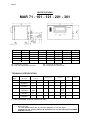
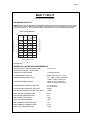
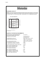
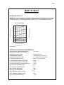
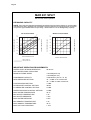
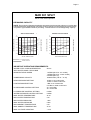
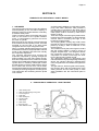
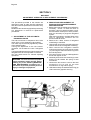
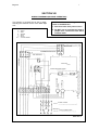
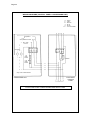
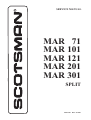
Page 1
Page 1
SERVICE MANUAL
MAR 71
MAR 101
MAR 121
MAR 201
MAR 301
SPLIT
SPLIT
090144.00
REV. 10/2001
Page 2
Page 2
FOREWORD
SCOTSMAN MAR SPLIT UNITS are available in
five basic models MAR 71, MAR 101, MAR 121,
MAR 201 and MAR 301 pre set, upon request, to
operate with fresh or sea water.
The refrigerating and electrical system must be
completed by the purchaser as per the instructions
given in this service manual who has to provide
for the complete condensing unit, its controls and
refrigerant tubings.
They come complete with a stainless steel cabinet,
with a drive motor at V. 230/50/3 or 400/50/3-N
Volt, with expansion valve, heat exchanger float
reservoir, time delay switch, bin thermostat, water
pump, ice spout switch, liquid solenoid valve, and
water pressure control.
We suggest to take time now to read this manual
which contains a lot of valuable informations on
the MAR Split System.
For any further queries regarding the care or
operation of the machine, please contact:
®®
ICE
SYSTEMS
SCOTSMAN - EUROPE - FRIMONT SPA
Via Puccini, 22 - 20010 Bettolino di Pogliano (Milano) Italy
Tel. +39-02-93960.1 (Aut. Sel.)- Telefax +39-02-93550500
Direct Line to Service & Parts:
Phone +39-0331-589305 - Fax +39-0331-584306
Website: www.scotsman-ice.com
E-Mail: [email protected]
Page 3
Page 3
TABLE OF
CONTENTS
Section I
Section II
Section III
Foreword
Table of contents
Specifications
GENERAL INFORMATION
General
Application area
Condensing unit
Control devices
Location considerations
Refrigerant lines
Hydraulic circuit
Ice storage room
Unit layout
INSTALLATION
Unpacking and inspection
Location and levelling
Refrigerant piping connections
Water piping connections
Water and refrigerant circuit
Electrical connections
Installation practice
Mar Split in multiple installation
Typical non-code commercial installation
page
2
3
4-9
10
10
10
11
12
12
12
12-14
15
16
16
16
17
17
18
19
20
20
TESTING
Complete system leak test
Complete system evacuation
Complete system charging
Start-up & Check-out
Operational check-out
21
21
21
21
21-22
PRINCIPLE OF OPERATION - HOW IT WORKS
ICE maker
MAR Split electrical/refrigeration
23
24-25
ADJUSTMENT & REMOVAL & REPLACEMENT
PROCEDURES
MAR Split
26-27
Section VI
MAINTENANCE & CLEANING INSTRUCTIONS
28-29
Section VII
SERVICE DIAGNOSIS
30-31
Section VIII
WIRING DIAGRAMS
32-33
Section IV
Section V
Page 4
Page 4
SPECIFICATIONS
MAR 71 - 101 - 121 - 201 - 301
MAR 71
MAR 101
MAR 121
MAR 201
MAR 301
A
876
876
876
1297
1297
B
621
621
621
661
661
C
380
380
380
715
715
Ø1
3/4" gas
3/4" gas
3/4" gas
3/4" gas
3/4" gas
Ø2
3/8" gas
3/8" gas
3/8" gas
1/2" gas
1/2" gas
Ø3
3/4" gas
3/4" gas
3/4" gas
28 mm
42 mm
Ø4
21 mm
21 mm
21 mm
21 mm
21 mm
Ø2 = LIQUID LINE CONNECTION
Ø4 = WATER OUTLET CONNECTION
Ø1 = WATER INLET FITTING
Ø3 = GAS LINE CONNECTION (SUCTION)
TECHNICAL SPECIFICATION
SPLIT
MODEL
Basic
Electricals
V
MAR 71
MAR 101
MAR 121
MAR 201
MAR 301
400/50/3 - N
230/50/3
400/50/3 - N
230/50/3
400/50/3 - N
230/50/3
400/50/3 - N
230/50/3
400/50/3 - N
230/50/3
Ice Production (*)
Kg/24 Hr.
Sea water
****
****
850
****
1800
Cooling req.ts
Drive Motor
Evap.T.°C
Kcal/Hr
Hp
Amp
510
-18
3200
1/2
670
-24
4800
1/2
1000
-24
6000
1/2
1650
-20
8250
1/2
2200
-30
9700
1/2
1.2
2.1
1.2
2.1
1.2
2.1
1.2
2.1
1.2
2.1
Fresh W.
Finish
Shipping
Weight
kg
SS
131
SS
131
SS
131
SS
223
SS
223
(*) "THICK ICE" SETTING - AT 10°/10°C (ambient/water temp.)
NOTE. Under these conditions ice production is of 2 mm thickness with output temperature of
about -20/-12°C.
For more details please refer to production diagrams on the next pages.
Condensing unit, control panel and installation are not provided by SCOTSMAN
EUROPE / Frimont.
Page 5
Page 5
MAR 71 SPLIT
Set for Fresh water Operation
ICE MAKING CAPACITY
NOTE. The production diagrams herebelow represented can be used as reference, since the data
indicated have been obtained with a air/water cooled condensing unit equipped with a hermetic
compressor type U.H. TFH 2480Z providing - 3200 Kcal/hr at -18 °C Refrigerating capacity.
AIR COOLED MODELS
Kg./24 h
520
o°C
10
480
AMBIENT TEMPERATURE
ICE PRODUCED PER 24 HRS.
500
21
460
440
420
32
400
38
380
360
340
32
27
21
15
10
°C
WATER TEMPERATURE
Thicker scale ice
IMPORTANT OPERATING REQUIREMENTS:
WATER LEVEL IN DRUM RESERVOIR
WITH WATER PUMP / SPRAY BAR
115-120 mm
DRUM ROTATING SPEED
1.1 RPM (thick ice)
CONDENSING CAPACITY
4900 Kcal/hr (TD 10 ÷ 15 °C)
HEAD PRESSURE SETTING
15 ÷ 17 Bar on air cooled units
17 Bar on water cooled unit
LOW PRESSURE SETTING
2.2 Bar on air cooled units
1.8 Bar on water cooled units
HI-PRESSURE CONTROL SETTING
34 ± 2 Bar A/C
30 ± 2 Bar W/C
LO-PRESSURE CONTROL SETTING
0.2 Bar
WATER PRESSURE CONTROL SETTING
0.8 Bar
MAX. WATER TEMPERATURE
35 °C
MIN. WATER TEMPERATURE
5 °C
MIN. WATER PRESSURE
1 atm.
MAX. WATER PRESSURE
5 atm.
MIN. AMBIENT TEMPERATURE
5 °C
MAX. AMBIENT TEMPERATURE
40 °C
MAX. VOLTAGE VARIATION
± 10%
Page 6
Page 6
MAR 101 SPLIT
Set for Fresh water Operation
ICE MAKING CAPACITY
NOTE. The production diagrams herebelow represented can be used as reference, since the data
indicated have been obtained with a air/water cooled condensing unit equipped with a hermetic
compressor type U.H. TAG 2516Z providing - 4800 Kcal/hr at -24 °C Refrigerating capacity.
Kg./24 h
750
o°C
700
10
650
21
AMBIENT TEMPERATURE
ICE PRODUCED PER 24 HRS.
AIR COOLED MODELS
32
600
38
550
500
450
32
27
21
15
10
°C
WATER TEMPERATURE
Thicker scale ice
IMPORTANT OPERATING REQUIREMENTS:
WATER LEVEL IN DRUM RESERVOIR
WITH WATER PUMP / SPRAY BAR
115-120 mm
DRUM ROTATING SPEED
1.5 RPM (thick ice)
2.3 RPM (thin ice)
CONDENSING CAPACITY
7500 Kcal/hr (TD 10 ÷ 15 °C)
HEAD PRESSURE SETTING
15 Bar on air cooled units
15 Bar on water cooled unit
LOW PRESSURE SETTING
1.6 Bar on air cooled units
HI-PRESSURE CONTROL SETTING
36 Bar
LO-PRESSURE CONTROL SETTING
0.2 Bar
WATER PRESSURE CONTROL SETTING
0.8 Bar
MAX. WATER TEMPERATURE
35 °C
MIN. WATER TEMPERATURE
5 °C
MIN. WATER PRESSURE
1 atm.
MAX. WATER PRESSURE
5 atm.
MIN. AMBIENT TEMPERATURE
5 °C
MAX. AMBIENT TEMPERATURE
40 °C
MAX. VOLTAGE VARIATION
± 10%
Page 7
Page 7
MAR 121 SPLIT
Set for Fresh water Operation
ICE MAKING CAPACITY
NOTE. The production diagrams herebelow represented can be used as reference, since the data
indicated have been obtained with a air/water cooled condensing unit equipped with a hermetic
compressor type U.H. TAG 2522Z providing - 6000 Kcal/hr at -24°C Refrigerating capacity.
AIR COOLED UNITS
10
1000
21
900
850
32
800
750
38
700
AMBIENT TEMPERATURE
ICE PRODUCED PER 24 HRS.
950
650
600
38
32
27
21
15
10
5 °C
WATER TEMPERATURE
Thicker scale ice
IMPORTANT OPERATING REQUIREMENTS:
WATER LEVEL IN DRUM RESERVOIR
WITH WATER PUMP / SPRAY BAR
115-120 mm
DRUM ROTATING SPEED
2.4 RPM (thick ice)
CONDENSING CAPACITY
9750 Kcal/hr (TD 10 ÷ 15 °C)
HEAD PRESSURE SETTING
14 ÷ 16 Bar on air cooled units
LOW PRESSURE SETTING
1.6 Bar on air cooled units
HI-PRESSURE CONTROL SETTING
36 Bar
LO-PRESSURE CONTROL SETTING
0.2 Bar
WATER PRESSURE CONTROL SETTING
0.8 Bar
MAX. WATER TEMPERATURE
35 °C
MIN. WATER TEMPERATURE
5 °C
MIN. WATER PRESSURE
1 atm.
MAX. WATER PRESSURE
5 atm.
MIN. AMBIENT TEMPERATURE
5 °C
MAX. AMBIENT TEMPERATURE
40 °C
MAX. VOLTAGE VARIATION
± 10%
Page 8
Page 8
MAR 201 SPLIT
Set for Fresh water Operation
ICE MAKING CAPACITY
NOTE. The production diagrams herebelow represented can be used as reference, since the data
indicated have been obtained with a air/water cooled condensing unit equipped with a hermetic
compressor type DORIN K500 CS providing - 8250 Kcal/hr at -20 °C Refrigerating capacity.
Kg.
1900
38
32
1500
38
1400
1300
1200
1100
1800
1700
1600
1500
1400
1300
38
32
27
21
15
10
5
°C
38
WATER TEMPERATURE
32
27
21
15
10
WATER TEMPERATURE
Thiner scale ice
Thicker scale ice
IMPORTANT OPERATING REQUIREMENTS:
WATER LEVEL IN DRUM RESERVOIR
WITH WATER PUMP / SPRAY BAR
90-95 mm
DRUM ROTATING SPEED
1.05 RPM (thick ice)
1.60 RPM (thin ice)
CONDENSING CAPACITY
11000 Kcal/hr (TD 10 ÷ 15 °C)
HEAD PRESSURE SETTING
16 ÷ 18 Bar on air cooled units
16 ÷ 17 Bar on water cooled unit
LOW PRESSURE SETTING
1.9 Bar
HI-PRESSURE CONTROL SETTING
36 Bar
LO-PRESSURE CONTROL SETTING
0.2 Bar
WATER PRESSURE CONTROL SETTING
0.8 Bar
MAX. WATER TEMPERATURE
35 °C
MIN. WATER TEMPERATURE
5 °C
MIN. WATER PRESSURE
1 atm.
MAX. WATER PRESSURE
5 atm.
MIN. AMBIENT TEMPERATURE
5 °C
MAX. AMBIENT TEMPERATURE
40 °C
MAX. VOLTAGE VARIATION
± 10%
5
°C
AMBIENT TEMPERATURE
32
21
o°C
DE 10 A' 38
ICE PRODUCED PER 24 HRS.
10
1600
ICE PRODUCED PER 24 HRS.
Kg.
1700
WATER COOLED UNITS
°C
10
21
AMBIENT TEMPERATURE
AIR COOLED UNITS
Page 9
Page 9
MAR 301 SPLIT
Set for Fresh water Operation
ICE MAKING CAPACITY
NOTE. The production diagrams herebelow represented can be used as reference, since the data
indicated have been obtained with a air/water cooled condensing unit equipped with a semihermetic
compressor type DORIN K1000 CS providing - 9700 Kcal/hr at -30 °C Refrigerating capacity.
WATER COOLED UNITS
°C
Kg.
2800
2200
32
10
2000
21
1800
32
38
38
1600
1400
o°C
2600
DE 10 A' 38
21
ICE PRODUCED PER 24 HRS.
10
2400
AMBIENT TEMPERATURE
ICE PRODUCED PER 24 HRS.
Kg.
2600
2400
2200
2000
1800
1600
38
32
27
21
15
10
5
°C
38
WATER TEMPERATURE
32
27
21
15
10
5
WATER TEMPERATURE
Thiner scale ice
Thicker scale ice
IMPORTANT OPERATING REQUIREMENTS:
WATER LEVEL IN DRUM RESERVOIR
WITH WATER PUMP / SPRAY BAR
90 mm
DRUM ROTATING SPEED
1.6 RPM (thick ice - air cooled)
1.8 RPM (thick ice - water cooled)
2.9 RPM (thin ice)
CONDENSING CAPACITY
16200 Kcal/hr (TD 10 ÷ 15 °C)
HEAD PRESSURE SETTING
15 Bar on air cooled units
14 Bar on water cooled unit
LOW PRESSURE SETTING
1 Bar on air cooled units
0.75 Bar on water cooled unit
HI-PRESSURE CONTROL SETTING
34 ± 2 A/C Bar
30 ± 2 W/C Bar
LO-PRESSURE CONTROL SETTING
0.2 Bar
WATER PRESSURE CONTROL SETTING
0.8 Bar
MAX. WATER TEMPERATURE
35 °C
MIN. WATER TEMPERATURE
5 °C
MIN. WATER PRESSURE
1 atm.
MAX. WATER PRESSURE
5 atm.
MIN. AMBIENT TEMPERATURE
5 °C
MAX. AMBIENT TEMPERATURE
40 °C
MAX. VOLTAGE VARIATION
± 10%
°C
AMBIENT TEMPERATURE
AIR COOLED UNITS
Page 10
Page 10
SECTION I
GENERAL INFORMATION
GENERAL
The MAR SPLIT UNITS are pratically the
"Evaporating Unit Section" complete with driving
mechanism and control devices, all encased in
their stainless steel cabinets, for making complete scale-ice maker system
The MAR SPLIT UNITS must be remotely
connected to a corresponding size "Condensing
Unit" to become a MAR scale-ice maker plant, it
is therefore of primary importance first, the
selection of the right type and size of all the
components to be used to complete the refrigerant
system and secondly - but not least - the skillness
of the refrigeration engineers that will proceed in
completing the system by making the refrigerant,
hydraulic and electrical connections.
APPLICATION AREA
The scale-ice maker system using the MAR Split
Units, applies to different sort of market situations
where scale-ice is needed. Most specific areas
are:
a) Fishing Vessels
b) Fish Markets and Fish Processing Plants
c) Supermarkets
d) Meat packaging plants
Basically they can go in any place where there is
a limited space situation or where the condensing
unit (compressor/condenser) must be located in
a room where noise and heat is not objectionable.
MAR Split can be set to produce "THICK ICE"
generally used in the fishing industry or "THIN
ICE" generally used in the meat processing
industry.
Standard versions are set for "THICK ICE"
production (about 2 mm thickness) and for fresh
water operation. Different conditions should be
specified when ordering the Units.
Modular combinations are possible to increase
output ice production.
COMPLETE SYSTEM INSTALLATION - How
it is made
The complete scale-ice making system can be
divided in three major groups, that are:
a) the compressor and condenser unit with their
own components with their own refrigerant
and water lines fittings and electric wires
terminal block.
b) the evaporator drum unit (MAR Split Unit
supplied by Frimont) complete with drive
mechanism, drive motor, refrigerant and water
lines fittings, refrigerants expansion valve and
electric wire junction box.
c) console panel and control box with compressor
ON/OFF switch, relay, timer, warning lights,
pressure gauges and electrical wire terminal
block.
For installation on board of fishing vessels where
the electrical power available is not sufficient or
adequate to run the compressor, a mechanical or
hydraulic drive transmission must be used.
These drive systems will not be covered in details
in this manual as it is assumed that their
fundamentals have been already mastered to
the installator engineer by more specific
publications.
CONDENSING UNIT
The compressor is truly the heart of the system,
when it becomes inoperative refrigeration
immediately ceases. Therefore the selection of
proper type and size of compressor together with
the proper type and size of condenser, their
components and controls, deserve the most of
attention by the refrigeration engineer.
For our MAR ice making system, the compressor
to take is consideration are ot two basic types:
a) the accessible Semi-Hermetic-MotorCompressor for installation on sites where the
electrical power supply is available in adequate
quantity and quality.
b) the Open Type Compressor for automative
installations (Fishing Vessels) with mechanical
pneumatic or hydraulic drive system through
a magnetic clutch.
Whatever is the type of compressor being used,
it is recommended, for its selection, to observe
the refrigerant capacity on the following table:
MAR 71
3200 Kcal/h -18°C Evap. Temp.
MAR 101
4800 Kcal/h -24°C Evap. Temp.
MAR 121
6000 Kcal/h -24°C Evap. Temp.
MAR 201
8250 Kcal/h -20°C Evap. Temp.
MAR 301
9700 Kcal/h -30°C Evap. Temp.
Page 11
Page 11
The condenser is basically a heat exchanger
where the heat absorded by the refrigerant during
the evaporating process is given to the condensing
medium which could be the air or the water.
The approximate heat transfer capacity for the
condenser selection is shown on the herebelow
table
MAR 71
MAR 101
MAR 121
MAR 201
MAR 301
4900 Kcal/h
7500 Kcal/h
9750 Kcal/h
11000 Kcal/h
16200 Kcal/h
Particular care must be deserved to the selection
of the water cooled condenser expecially the
marine type for fishing vessels installation.
They can be marine type (cupro-nickel) tube
within a tube condenser with plasticized heads.
With water inlet temperature of +20°C and outlet
of +30°C at condensing temperature of 32°C the
water consumption should be:
MAR 71
MAR 101
MAR 121
MAR 201
MAR 301
300 lt/hr
450 lt/hr
84*****h
1200 lt/hr
1600 lt/hr
When using marine type condenser a marine
type, water regulating valve is requested as well
to modulate the cooling water flow within
condenser.
Recommendend valve is the pressure actuated
"PENN".
The Liquid receiver is a storage tank for liquid
refrigerant that can be useful on refrigeration
split installation to make the quantity of refrigerant
in the system less critical.
It is normally provided with two service valves
and occasionally can be built-in the bottom of
condenser. It is a common component used in
refrigeration plant and should be large enough to
hold all the refrigerant in the system.
The Oil separator should be filled with oil during
installation until the float valve just begins to
open. This oil quantity always remains in the
separator and would otherwise be taken from the
compressor.
It is well known that when the compressor
operates, small amount of oil is pumped out
along with the hot compressed vapor and to
prevent it from going any further in the system,
the oil separator traps it to return, upon opening
of its float valve, to the crankcase of the
compressor.
CONTROL DEVICES
The scale-ice maker system must be completed
with all the necessary safety devices and controls
in order to fully protect it and to minimize
operational checks and functions, however any
excess in using automatic controls and protections
may complicate the situation at the point that
some of the controls be eliminated later, by the
user.
In order to help the installator engineer to decide
with which controls he has to equip a given
system, we cover all the necessary ones
mentioning for each of them the positive factors
and eventually the negative ones.
High Pressure Control
Very important - No negative factors Set to
values shown on techn. spech. Not supplied.
Water Pressure Control
Very important - No negative factors Set to 0.8
atm-cut-in - 0.5 atm cut-out. Supplied.
Lo Pressure Control
Very important because in case of refrigerant
leaks at the evaporator, it prevents to draw in the
system some water from the drum reservoir. It
also prevents to draw air through the compressor
crank-shaft seal. This may occure during vacuum
operations of the system.
However, it may inopportunely trip-off at the
system start-up and if suction operating pressure,
on account of the excessive rotating speed of
compressor or excessive compressor capacity,
is very close and gets below its setting value,
which is 0.2 atm. Not supplied.
Page 12
Page 12
LOCATION CONSIDERATION
WARNING - The MAR SCALE ICE MAKERS
are not designed for outdoors installations
where air temperature falls below 5°C
(40°F) and may exceed 40°C (100°F)
Operating a machine with an unacceptable
configuration will void the refrigeration system
warranty.
For installation on board of fishing vessels, the
location for the condensing unit is generally the
engine room, while the evaporator unit can be
permanently placed in some area of the deckhouse or if it is not too cold (not below 5°C), inside
the fish and ice hold.
In case a stand is going to be made and used plan
for adequately fastening the MAR SPLIT UNIT.
The stand must be steady made to do not cause
excessive vibrations and must have the possibility
to be securely fastened to the wall or to the floor.
In relation to evaporator position and situation a
certain kind of ice chute is required. Make sure to
have it available for the start-up of the system.
REFRIGERANT LINES
Inner diameter of refrigerant lines going from
condensing unit to evaporator unit and back,
must be of adequate size in relation to tubing
lenght.
The table below show the recommended sizes of
refrigerant lines:
MODELL
Lenght of tubes
MAR 71
MAR 101
MAR 121
MAR 201
MAR 301
5 to 15 mt
5 to 15 mt
5 to 15 mt
5 to 15 mt
5 to 15 mt
Suction line Liquid line
18 mm
18 mm
18 mm
28 mm
42 mm
12 mm
12 mm
12 mm
12 mm
12 mm
2. Insulate lines that will be exposed to outside
temperature that will be below freezing for
extended period of time.
3. Follow straight line routing, when possible,
however give to the suction line a certain pitch
(2 cm per meter).
On liquid line be sure to do not have restrictions.
Bends and fittings should be the minimum
necessary as they can increase the resistance
to the fluid flow.
4. To prevent any condensing unit vibration
travelling into the lines, vibration absirbers
may be installed in the suction and the liquid
lines near the condensing unit.
Because the appearence of an installation is
important, the piping should be put-in as
neathly as possible.
For best sound absorb-tion, it is best to put-in
two absorbers in each line, one vertically and
one horizontally.
For evacuation and charging operations two
service valves must be provided.
One on the liquid line and one on the suction
line.
5. A drier and a sight glass should be installed
in the liquid line at the condensing unit.
HYDRAULIC CIRCUIT
Another item that requires a preliminarly attenzion
for the MAR SPLIT installation is the water
supply to the ice making section and to the
condensing unit case a water cooled condenser
is being used. Separate water linea are
recommended with hand shut-off valve and water
filter on individual line.
Remember:
– Maximum Water Temperature
– Minimum Water Temperature
– Minimum Water Pressure
– Maximum Water Pressure
35°C
5°C
1 atm
5 atm
The Ice Making Section (MAR SPLIT UNIT)
generally requires:
– 21 lt/hr
– 29 lt/hr
– 42 lt/hr
– 70 lt/hr
– 91 lt/hr
MAR 71
MAR 101
MAR 121
MAR 201
MAR 301
of constant water supply.
The water consumption of the water cooled
condenser (in case of water cooled condensing
unit) to be taken on account, with water inlet
temperature at 15°C is:
– 300 lt/hr
– 480 lt/hr
– 1200 lt/hr
– 1500 lt/hr
– 1600 lt/hr
MAR 71
MAR 101
MAR 121
MAR 201
MAR 301
For installation on fishing vessels, using
seawater, to carry sea water from sea chest to
the condensing unit and to evaporating unit
through appropriate strainers, you may use
aluminium brass pipes or PHE plastic pipes to
avoid corrosion problems.
Never use copper tubes.
ICE STORAGE ROOM
Ice storage situations are of two kinds:
a) Short terms storage
b) Extended terms storage
Being, as stated scale ice made by MAR
machines flat, dry and subcooled, therefore with
the tendency to stick toghether, particular
attention is required for proper ice storage
conditions for better ice handling. An insulated
ice storage bin or room is always required, then
according to ice end use application, this can be
refrigerated or non-refrigerated.
Page 13
Page 13
Also a weight volume ratio of 2.1 cm. mt. per ton,
must be taken into consideration for correct ice
storage.
is being used on a daily basis, it is not necessary
to provide cooling for the ice storage room.
a) Non-refrigerated room for short term
storage
The scale ice is produced continuously for 24
Hours per day, whereas the use period is
generally for no longer than 8 hours per day.
Therefore storage facilities should be provided
to accomodate a minimum of 16 hours of
production, this means that every MAR ice
machine must be installed with a properly
insulated storage room which should have a
minimum capacity of 2/3 the daily ice
production.
With a well insulated room and duly subcooled
scale ice, the limited losses of heat through the
walls of a properly designed room with
adequate arrangements, are largely offset,
and excess melting will not occur. In most
situations where whole quantity of ice produced
b) Refrigerated room for extended storage
and long distance conveying
When scale ice is to be transported at a
considerable distance, such as aboard fishing
vessels, or in locations with normal ambient
temperatures conditions, or when used in
industrial plants where demand is intermittent,
its subcooling power must be preserved
absolutely in the storage bin by a proper
cooling system keeping air temperature at a
pre-established and constant value. The ideal
ice storage room is the type with mechanically
refrigerated jacket space surrounding the ice
bin.
Good practice calls for an ice storage capacity
of about two times the daily ice machines
production with an inside temperature of -6°C
minimum (20°F).
Page 14
Page 14
NON REFRIGERATED ICE STORAGE ROOM
REFRIGERATED ICE STORAGE ROOM
(Jacket system)
1
2
3
4
5
6
7
8
9
10
11
12
13
14
15
Condensing unit
Liquid line
Evaporator drum unit
Suction line
Power supply line
Hand disconnect switch
Water supply line
Hand shut-off valve
Water filter
Condenser water inlet
Condenser water outlet
Evaporator water supply
Water drain line
Liquid line service valve
Suction line service valve
1
2
3
4
5
6
7
8
9
10
11
12
13
Condensing unit
Liquid line
Evaporator drum unit
Suction line
Power supply line
Hand disconnect switch
Water supply line
Hand shut-off valve
Water filter
Condenser water inlet
Condenser water outlet
Evaporator water supply
Water drain line
14
15
16
17
Refrigerant coil
Insulated panel
Air gap
Ice bulkhead
Page 15
Page 15
WATER INLET
R404 LIQUID
R404 GAS
WATER OUTLET
UNIT LAYOUT AND OVERALL DIMENSIONS
DENOMIN.
MAR SPLIT 71-101-121
MAR SPLIT 201-301
A
278 (10 15/16)
278 (10 15/16)
B
621 (24 13/32)
661 (26 1/32)
C
876 (34 31/64)
1296 (51 1/32)
D
380 (14 61/64)
715 (28 5/32)
E
248
290 (11 7/16)
(9 3/4)
Page 16
Page 16
SECTION II
INSTALLATION
MAR SPLIT UNIT - UNPACKING AND
INSPECTION
1. Visually inspect the exterior of the shipping
container and skid and any severe demage
noted should be reported to the delivery carrier;
and a concealed damage claim filled subject
to internal inspection with carrier representative present.
2. Remove the packing and remove the side
panels to unloose the shipping bolts securing
the unit to the skid.
3. Remove screw and all panels from cabinet
and inspect for any concealed damage. Notify
carrier of any concealed damage claims as
stated in step 1 above.
4. Remove all internal packing from unit
compartment.
5. Check that refrigerant lines do not rub or
touch lines or surfaces and that all wires are
securely fastened to their terminals.
6. Use clean damp cloth or disposable paper
wiper to wipe clean the exterior surface of the
cabinet.
7. See DATA PLATE on the cabinet base and
check that the location source voltage
corresponds with the voltage specified on the
dataplate.
CAUTION - Unproper voltage supplied to
the icemaker will void your parts
replacement programm.
MAR SPLIT UNIT - LOCATION AND
LEVELLING
1. Position the MAR SPLIT UNIT in the selected
permanent location which could be on top of
ice storage cabinets, on the side of cold
storage room supported by special pre-set
stands or, in case of fishing vessel installation,
inside or on top of the fish hold.
2. After having placed the unit on the support
stand, level the cabinet on both the left to righ
and front to rear directions, by inserting
between the unit base and a support stand
few rubber pads. Fit in unit base holes in the
cabinet, appropriate bolts to fasten unit to
stand.
Make sure to leave enough space around the
unit to allow access to internal components
for inspection and servicing and also for the
fitting of the ice chute if needed.
3. Proceed to position the condensing unit in its
location and to mount it firmly to avoid a
sudden shift that would endager the refrigerant
lines. Precautions to be observed vary with
the kind of situation in which the unit is to be
placed. The area should be well ventilated to
permit escape of refrigerants in case unit
develops a leak.
MAR SPLIT UNIT - REFRIGERANT PIPING
CONNECTION
Fitting sizes:
MAR 71-101-121
MAR 201
MAR 301
Liquid Line
Suction Line
3/8" Gas
1/2" Gas
1/2" Gas
3/4" Gas
Ø 28 mm
Ø 42 mm
Take extreme care to keep refrigeration tubing
clean and dry prior to installation.
Following procedure should be followed:
a) Do not leave dehydrated compressor or filterdrier open to the atmosphere any longer than
it is absolutely necessary. (One or two minutes
maximum suggested).
b) Use only refrigeration grade copper-tubing,
properly sealed against contamination.
c) Permanent suction lines filters and liquid line
filter-driers are recommended in all filled
installed system.
d) When brazing refrigerant lines, an inert gas
should be passed through the line at low
pressure to prevent scaling and oxidation
inside the tubing. Dry nitrogen is preferred.
e) Line connection to vibration eliminators be
made with silver solder alloy.
Arrange that refrigerant lines run along the walls
and cellings and be supported at intervals frequent
enough to keep tubing atraight and firmly in
place. In all cases the tubing should be run
horizontally and vertically with neat looking bends
of as perfect radius as possible.
The liquid line presents no difficulties as to its
sland and position, but you must install the suction
line so the tubing will drain toward the compressor.
During preparation of liquid line take the necessary
measure to install after evacuation of system, the
filter-drier of suitable size for constant operation.
You may as well consider to install on suction line
a suction tube filter, specially if the required
cleaness cannot be guaranteed.
After all lines are connected, the entire system
must be leak tested.
The complete system should be pressurized to
no-more than 12-13 atm. with refrigerant and dry
nitrogen or dry CO2 for being leak tested by
means of an electronic type leak detector.
Page 17
Page 17
For pressurizing, evacuating and charging the
system, two service valves are necessary; one
should be in the Suction Line at the inlet side of
suction filter and one should be in the Liquid Line
at the outlet side of filter dryer.
The two Service Valves, if properly capped can
be left permanently in the system. Connection
should be 3/8" or 1/2" size.
MAR SPLIT UNIT - WATER PIPING
CONNECTIONS (PLUMBINGS)
MAR SPLIT UNIT is supplied with float valve in
position to maintain the water level in drum
reservoir at the height required for fresh water
operation or if required, for sea water operation.
Water inlet line must go directly to float valve line
fitting of 3/4" gas, (copper tube is not
recommended for sea water supply) also make
sure to fit on this same a hand shut-off valve
close enough to MAR unit and a proper kind and
size of filter strainer.
Incoming water geoes through the float reservoir
first and then to drum basin.
Outlet water line should be shaped adequately to
drain by gravity any water passing through it.
Water outlet fitting from float reservoir requires a
20 m/m I.D. water hose.
All plumbing connections should be made in
accordance with local plumbing codes.
WATER AND REFRIGERANT CIRCUIT - SPLIT UNITS
1.
2.
3.
4.
5.
6.
7.
Liquid line
Heat exchanger
Automatic expansion valve
Suction line
Water inlet
Float valve
Water basin
8.
9.
10.
11.
12.
13.
Evaporation drum
Scraping blade
Water pump
Spray bar
Water tube - Pump / spray bar
Liquid line valve
Page 18
MAR SPLIT UNIT - ELECTRICAL
CONNECTION
The supply power, voltage frequency and phase
must coincide with unit nameplate. MAR Split
units are internally wired and ready for field
wiring connections which must be made in
accordance with any local codes that may apply.
Wires should be of adequate size to handle the
connected load, individually fused (see
specifications at page 5) and provided with ground
line.
The maximum allowable voltage variation, should
not exceed ten percent of the nameplate rating,
even under starting conditions.
Low voltages can cause erratic operation and
may be responsible for serious damages to the
overload switch and motor windings.
Make the necessary steps so that the MAR Split
Page 18
Unit be electrically connected to the condensing
unit control box contactor as illustrated on the
following wiring diagrams representing three
different electric supply line situation which are
respectively. 230/50/3 or 400/50/3-N.
WARNING - Correct Drum rotation - The
evaporator drum drive motor being a
threephase motor wired for 380 V. It is of
estreme importance to check immediately
upon unit start-up that motor rotates
CLOCKWISE in order that gear motor
pulley rotates in the direction of the
ARROW on it indicated. Should the motor
turn counterclockwise, it is necessary to
instantly switch-off the unit and
interchange one polarity at terminal block
connection at main electric cord.
Page 19
Page 19
INSTALLATION PRACTICE SPLIT
UNIT ASHORE
INSTALLATION PRACTICE SPLIT UNIT
ON OFFSHORE FISHING VESSEL
1
2
3
4
5
6
7
8
9
10
11
12
13
1
2
3
4
5
6
7
8
9
Condensing unit
Liquid line
Evaporator drum unit
Suction line
Power supply line
Hand disconnect switch
Water supply line
Hand shut-off valve
Water filter
Condenser water inlet
Condenser water outlet
Evaporator water supply
Water drain line
Deck house
Control panel & main switch
Ice chute
Evaporator drum unit
Ice hold
Fishing room
Réfrigérant lines
Condensing unit
Engine room
Page 20
Page 20
MAR SPLIT IN MULTIPLE INSTALLATION
In multiple installation various types of commercial
refrigerating equipment are connected to the
same condensing unit, which is normally located
in the machine room, as often occurs in
supermarkets.
MAR SPLIT can be one of the refrigerant units
connected to a multiple use condensing unit.
In this kind of installation it will be best to replace
the standard AEV refrigerant control with a
corresponding size AMXV control, which, in
relation to the multiple installation situations (great
evaporating temperature difference) could be of
two temperature type.
Also a manifold with hand shut-off valves on
both liquid and suction line is recommended for
these installations.
In many multiple installations check valves are
put in the suction line of the coldest evaporator to
prevent that warmer higher pressure low-side
vapor moves into colder evaporator during the off
periods.
Also a pressure control valve should be installed
MAR SPLIT ICE MAKER
on MAR SPLIT suction line to maintain constant
pressure on evaporator drum.
Therefore, for the MAR SPLIT multiple installation
you may need:
1. Automatic Expansion valve
The automatic expansion valve is the leading
multiple evaporator system refrigerant control
as it does not regulate the low side pressure,
but, rather control the filling of the evaporator
with refrigerant, it is important to use a valve
for the correct capacity.
2. Solenoid valve
Two-ways type to be connected in series with
any MAR SPLIT protecting and starting device.
3. Pressure Control valve
To be placed on the MAR SPLIT suction line.
It will mantain constant pressure on MAR
SPLIT evaporator drum.
4. Manifold with hand shut-off valve
One to be placed on the liquid line and the
other on suction line to isolate MAR SPLIT
unit when necessary.
TYPICAL NON-CODE COMMERCIAL INSTALLATION
4. Suction line shutoff valves
5. Liquid line shutoff valves
1. Power line
2. Main switch
3. Relay / Starter
MEET ROOM
DISPLAY CASE
CONDENSING UNIT
Installation of MAR SPLIT in multiple system
should be done in the following order.
1. Put MAR SPLIT unit in place.
See Sec. II Location & Levelling.
2. Install valves and controls.
3. Install tubings.
See Sec. II Refrigerant piping connections.
4. Make water piping connections.
See Sec. II Plumbing.
5. Make electrical connections
See Sec. II Electrical connections.
6. Check for leaks.
See Sec. II Leak Test.
7. Dehydrate installation.
See Sec. III Evacuation / Charging.
8. Start unit.
See Sec. III Operazional Check-out.
Page 21
Page 21
SECTION III
TESTING
COMPLETE SYSTEM LEAK TESTS
During pressure testing for leaks, keep the
compressor suction service valve and discharge
service valve closed to prevent air and moisture
from entering the compressor. All other valves in
the system must be open.
Sufficient liquid refrigerant shall be charged into
the system to raise the pressure to 2.5 atm. and
dry nitrogen added to obtain the desired test
pressure (20.5 atm is sufficient).
Leak testing shall be performed with an electronic
leak detector, unless the use of a halide torch is
specifically authorized by the owner.
Refrigeration piping will not be acceptable unless
it is gas tight.
If any leaks are found, isolate the defective area,
discharge the gas and repair the leaks and then
repeat the test. When testing has been completed
release all pressure freely to atmosphere.
COMPLETE SYSTEM EVACUATION
The system shall be evacuated with a vacuum
pump specifically manufactured for vacuum duty,
having a capacity of pulling a vacuum of 50
microns or less.
Evacuation of the system must never be done by
the use of the refrigerant compressor. The pump
should be connected to both the low and high
side evacuation valves with vacuum hoses. The
compressor service valves should remain closed.
A high vacuum gauge capable of registering
pressure in microns should be attached to the
system pressure readings.
Never put the compressor in operation. To check
system pressure, a hand valve must be provided
between the pressure gauge and the vacuum
pump which can be closed to isolate the system
and check the pressure.
Evacuate the system to an absolute pressure not
exceeding 1,500 microns. Creak the vacuum to
excess pressure of 0,15 atm (1 psig) with the
refrigerant to be used in the system.
Repeat the evacuation process again breaking
the vacuum with refrigerant. Install a definitive
drier of the required size in the liquid, open the
compressor suction and discharge valves and
evacuate to an absolute pressure not exceeding
500 microns. Leave the vacuum pump running
for not less than two hours without interruption.
Raise the system pressure to 0,15 atm (1 psig)
with refrigerant and remove the vacuum pump.
Wheigh the refrigerant drum before charging so
that an accurate record can be kept of the weight
of refrigerant put in the system. It refrigerant is
added to the system through the suction side on
the compressor, charge in vapor form only. The
process used most often to determine correct
refrigerant charge is to observe the refrigerant
flow in the sight glass in the liquid line.
As steady supply of liquid is necessary for proper
functioning of expansion valves; it can be
assumed that the system has been correctly
charged when a clear flow of liquid refrigerant is
visible.
Bubbles or foam usually indicate insufficient
refrigerant, even if there could be other reason
for the bubbles or foam to appear in the sight
glass. So, the practice to relay on the sight glass
only to determine whether the systems is correctly
charged is certainly good but not fully positive.
After the final leak test, refrigerant lines exposed
high ambient conditions should be insulated to
reduce heat pick-up and prevent the formation of
flash gas in the liquid lines.
Suction line should be insulated if exposed, to
prevent condensation.
START-UP - CHECK-OUT
Compressor and condensing unit will normally
be delivered to the job with sufficient oil for
average installation.
Check compressor for proper oil level and, if
necessary, add sufficient oil to bring the level to
the center of the cranckase sight glass.
Use only refrigeration oil recommended by the
compressor manufacturer.
Remove or loosen shipping retainers under
motor-compressor. Make sure hold down nuts
on spring mounted compressor are not touching
the compressor feet.
Check electrical connections. Be sure they are
all tight. Check high and low pressure control,
water valves, pressure regulating valves, safety
controls and adjust if necessary.
OPERATION CHECK-OUT
After system has been charged and checked-out
make sure to correctly position, attached to the
unit ice spout, the require chute (not supplied).
COMPLETE SYSTEM - CHARGING
Perform a through re-check of entire system as
per following steps.
Refrigerant shall be charged directly from original
drums through a combination filter drier.
Charge the system by means of a charging fitting
in the liquid line.
1. Make sure to open the water supply line shutoff valve and that water flows freely from float
valve into float reservoir and from this to the
drum basin.
Page 22
Page 22
2. Put power to the system in order to start-up
the evaporator drive motor, the water pump
and the compressor.
3. Observe that evaporator drum rotates in the
right direction, namely towards the scraping
blade.
WARNING - Drum drive motor is
threephase, at the unit startup, care must
be taken to ensure of the correct rotation
direction of drum.
In case of wrong rotation interchange the
phases by interchanging the lead wire
connections of main cord.
4. Check compressor head and suction
pressures. If not within system design limits,
determine why and take corrective action.
5. For water cooled condensing unit check the
water flowing out of the condenser to see if it
drains properly.
6. Observe if ice skin tends to cover entire drum
surface and is being scraped-off correctly by
the blade.
7. Check liquid line sight glass and expansion
valve operation. If there are indications that
more refrigerant is required leak test all
connections before adding refrigerant.
8. Observe oil level in compressor crankcase
sight glass and add oil as necessary to bring
level to center of the sight glass.
9. Let the system operate for at least two hours,
then check one by one the operation of each
individual control and protective device for
proper setting.
10. Eliminate any excessive vibration or noise
and pulleys misalignement.
11. Observe that evaporator drum is frosted all
over from end to end. If this is not the case
setting of refrigerant expansion valve may be
necessary.
For proper adjustement of this valve turn the
valve setting stem of one eight of a turn
counter-clockwise to allow more refrigerant
to flow until the evaporator drum surface is
evenly frosted from end to end.
In case there is an excessive frost back on
the suction line and frost start to form on
compressor suction service valve, slightly
turn clockwise the expansion valve setting
stem until the frost back on the compressor
service valve melts over.
Indicative Operating Pressure - With Fresh Water Supply - Water Cooled System
Head Pressure (bar)
Suction
Drum R.P.M. (thick ice)
MAR 71
17
1.8
1.1
MAR 101
15
1.6
1.5
MAR 121
15
1.6
2.4
MAR 201
15
1.6
1.05
MAR 301
14
0.75
1.8
Indicative Operating Pressure - With Sea Water Supply - Water Cooled System
MAR 121
Head Pressure (bar)
Suction
Drum R.P.M. (thick ice)
1.52
MAR 301
1.82
12. In relation to the desired quality of scale ice,
review the position of float reservoir to see if
water in drum reservoir is at the corresponding
level.
Water level must not exceed in any case the
following limits:
MAR 71 - MAR 101 - MAR 121
MAR 201 - MAR 301
115-120 mm
90-95 mm
13. Observe that ice slides through spout opening
with no difficulties. Clearence between the
blade and drum surface must be 0,10 m/m.
Transparent plastic chute must be flat.
14. When the system is performing satisfactorily
go over with the owner/user to all significant
specifications, the start-up and operations.
Answer alla questions about the care and
attention to give to the ice making system.
Page 23
Page 23
SECTION IV
PRINCIPLES OF OPERATIONS - HOW IT WORKS
1. ICE MAKER
The revolving drum which may be of two different
sizes depending on the ice maker capacity, is
basically made of a cylinder skeleton covered by
a stainless steel jacket.
There is a channel, about 15 m/m deep and 15 m/m
wide on the surface of the cylinder skeleton
which, in a spiral pattern, goes from one end to
the other of cylinder.
Both the ends of the channel communicate with
a bore made in the left cylinder journal. The head
manifold on the left side is for either liquid
refrigerant inlet and vapor refrigerant outlet.
When a cylinder stainless steel jacket is forced
and sealed on the drum, the spiral pattern channel
made for the refrigerant flow becomes virtually
the evaporator serpentine.
The metered refrigerant that reaches the
evaporator serpentine by passing throught the
head manifold in the left side cylinder journal,
boils and evaporatores as it comes into contact
with the drum metal jacket. About one third of the
cylinder drum is constantly submerged in water
this will allow the cylinder metal jacket to draw a
film of water that, as soon as it comes afloat,
freezes almost instantly due to the heat absorption
created by the boiling refrigerant circulating in the
inner serpentine and scrubbing with the jacket
inner surface.
On fresh water installation a combination of water
pump and water distributor tube provides a
constant flow of cold water to the upper side of
the evaporator drum so to have an extended
metal jacket surface covered by water and a
thicker ice layer.
Then the ice layer of the emerged cylinder sector
has a fraction of time to solidify, dry and eventually
subcool before contacting the edge of the
horizontal scraping blade.
The scraping blade, of heavy duty metal, cause
the peel off of the ice sheet formed on the drum
jacket by racking it while it advances on the
revolving drum.
The ice sheet is so dry that, when it gets in contact
with the scraping blade, it cracks in a form of
irregular shaped chips. The refrigerant leaves
the evaporator serpentine to return to the
compressor via suction line through the inner
bore of the left side cylinder journal.
The refrigerant sealing in inlet/outlet head
manifold is assured by specially designed sealing
device, the cylinder is driven by separate drive
motor and gear reducer located on the right basin
frame.
The gear reducer, the driving belt with its pulley,
the revolving drum with the rotating part of the
sealing devices and the water pump on fresh
water installation are the mechanical parts in
motion.
2. PRINCIPLES OF OPERATION - HOW IT WORKS
1.
2.
3.
4.
5.
6.
7.
8.
9.
10.
Water drawing area
Water sprayed freezing cooling area
Sub-cooling area
Float valve
Water feeding line
Scraping blade
Water pump
Water basin
Revolving drum
Water distributor tube
Page 24
Page 24
3. MAR SPLIT - ELECTRICAL /
REFRIGERATION
The electrical circuit consists of drive motor,
water pump, water pressure switch, spout switch
and time delay safety device.
A. Drive motor
The evaporator drum drive motor is a three
phase motor of 1/2 HP wired for 380/220 Volts
50/60 Hz - 1,2/2,1 Amps - 1400 R.P.M. with
inherent thermal protector.
IMPORTANT - When this motor is
disconnected or the entire unit is disconnected,
it is necessary - when resuming the electrical
connection to immediately make sure that
drive motor rotates clockwise facing the
unit front.
Failure to this, may result in wrong rotation of
evaporator drum with the risk of major
damages to the system.
B. Water failure Switch
This switch used as safety device when low or
interrupted supply water conditions are
encountered.
Operates on pressure between supply line
and feed line to water reservoir.
Range is 0,8 atm (10 psi) off and 1,2 (17 psi).
Cuts off complete unit and Resets
automatically.
C. Ice Spout Safety Switch
Located on top of the Ice Spout, the Safety
Switch is operated by a plate on top of the ice
chute by the ice backing up in the spout.
The switch will shut-off entire ice making
mechanism.
D. Timer - Time Delay - With setting dial from 0
to 30 min. It delays the energizing of main
contactor in relation to its time setting,
preventing short cyclings of units motor
compressor and drive motor.
E. Automatic Expansion Valve (A.E.V.)
The automatic expansion valve controls the
refrigerant when passing from the liquid line
to the evaporator. As the pressure decreases
on the low side, the expansion Valve open
and refrigerant escapes into the evaporator
drum channel where it absorbs heat from
water while evaporating. The valve maintains
a constant pressure in the evaporator coil
when the system is running indipendently of
the amount of refrigerant in the system.
This valve has an adjustment which may be
manually regulated to give the evaporator coil
the desired amount of refrigerant.
Turning the adjustment to the left,
counterclockwise, will increase the rate of
flow which is controlled by the pressure in the
evaporator.
When the compressor is not running the valve
will remain closed as the low side pressure
will be high enough to close the expansion
valve.
- MAR Split 71-101-121 - is equipped with an
expansion valve having an orifice of 2,5 m/m.
- MAR Split 201-301 - is equipped with an
expansion valve having an orifice of 4,5 m/m.
F. Evaporator Drum
Refrigerant inlet/outlet takes place on left
side journal.
The drum body is covered by a jacket in
special stainless steel resistant to the water
corrosion.
The front edge of the scraping blade must
have a clearance of minimum 0.10 m/m from
cylinder metal jacket.
G. Refrigerant Seal System
Housed in the refrigerant inlet/outlet manifold
located on the evaporator drum left side
journal, is a leakproof joint. This joint is made
with seals that are carefully designed and
installed. The seals use two rubbing surfaces.
One surface tourns with the cylinder journal
and is sealed on it with on O ring of synthetic
material. The other surface is stationary and
fitted in its housing with leak-proof O rings.
The rubbing surfaces (optically flats) are made
of two different material that are: hardenend
steel for the rotating ring and graphite for the
stationary ring.
The rotating parts are:
a) the spring collar
b) the compression spring
c) the stainless steel seal ring with O ring.
The stationary parts are:
a) the graphitic ring with O ring
b) the stainless steel housing ring with gasket
and O rings.
H. Heat Exchanger
MAR Split 71, 101, 121, 201 and 301 have a
heat exchanger mounted in the suction and
liquid line to reduce flash gas in the liquid line,
to reduce liquid refrigerant in the suctionand
to subcool the liquid refrigerant thereby
increasing the operating efficiency.
I. Strainer Filter
All MAR Splits mount on liquid line a wiremesh
type of filter to prevent that screen of filter of
the expansion valve could becopme clogged
from dirt thereby stopping the refrigerant flow.
connections.
L. Motor Shaft Pulley
MAR Split units are generally equipped with
"Step pulley" and by changing the belt from
one groove to the other the speed of drum can
be changed.
MAR Machines are factory delivered with V
belt on smaller dia V groove of step pulley to
rotate the evaporator drum at the lowest
possible R.P.M. to obtain "THICK" (2 m/m
gauge) scale ice.
Page 25
Page 25
Normal drum R.P.M. for "THICK" ice
production are:
MAR 71 - 1.1 RPM
MAR 101 - 1.5 RPM
MAR 121 - 2.4 RPM
MAR 201 - 1.05 RPM
MAR 301 - 1.6 RPM
M. V Belt
V belts used on motor shaft pulley and gear
box are type:
MAR
71
MAR
101
MAR
121
MAR
201
MAR
301
Z 30 3/4
Z 33
Z 33
Z 35
Z 36 3/4
When changing the V belt from one groove to
another, be careful to adjust it for proper
tension and alignement.
It should be snug not tight. A way to roughly
check belt tension is to apply a firm hand
pressure in the middle of the longest belt
span. If the belt is correctly tensioned, you
should be able to depress it about 5 m/m out
of line.
N. Gear Reducer
The gear reducer is mounted on the right side
frame of evaporator drum basin to which it is
firmaly secured with four nuts.
The gear reducer bore in which passes the
drum shaft to be driven, has a keyway.
Two fiber keys are used to engage the gear
reducer to the drum shaft, they are in series in
the gear reducer bore, and shaft keyways.
Should the driving strain be excessive, the
two fiber keys will shear.
MAR 71, 101 and 121 are equipped with a
gear reducer having a ratio of 1/570.
MAR 201 and 301 have a gear reducer with a
ratio of 1/525.
The gear reducers are greased for life,
therefore they do not require any maintenance.
O. Water pump / spay bar
Used only on FRESH WATER version the
water pump is mounted on the rear left side of
evaporator drum basin.
It supplies water under gentle pressure to
the spray bar located on top of evaporator
drum.
P. Ice Level Control
Could not be necessary - It is subject to
corrosion in marine application. Supplied.
Q. ON/OFF switch
The manual start-up or switching of the entire
system requires the attention of the operator
who may instantly keep control of the situation,
therefore it is preferable to any timed switch.
To be installed en Main Ctl Panel.
R. Warning Lights
Monitoring unit performance and interventions
of safety controls. To be installed en Main Ctl.
Panel.
S. Master Relay or Contactor
With electric coil connected in series with
safety controls for operation in safe conditions
of condensing and evaporating unit. Supplied.
T. Time Delay Relay
Constructed with a time delay action so that
the relay must be energized for about 10
minutes before the magnetic coil can actuate
the contacts through wgich compressor and
evaporator drive motor is energized.
This type of relay prevents compressor and
evaporator drive motor short cycling which
could be harmfull to evaporator drive
mechanism due to ice skin being formed on
the evaporator drum jacked that get thicker
and sticker during evaporator drive motor offmomentum. Supplied.
U. Daily timer
Could not be necessary - Can be used in
place of the ice level control and of the ON/
OFF switch. Upon request.
V. Liquid Line - Solenoid Valve
Necessary to stop refrigerant flow when not
desired. To be located on the liquid line past
the drier is electrically connected to
compressor contactor or relay to stop flooding
the evaporator and suction side during
compressor off periods. Supplied.
W. Hi and Lo Pressure indicating gauges
Could not be necessary - They are subject to
setting alternations. Not supplied.
Page 26
Page 26
SECTION V
MAR SPLIT
ADJUSTMENT & REMOVAL & REPLACEMENT PROCEDURES
The procedures provided in this section are
arranged in order to make specific adjustment
and removal and replacement information easy
to locate.
Read the instructions throughly before performing
any adjustment or removal or replacement
procedures.
1. ADJUSTMENT OF THE AUTOMATIC
EXPANSION VALVE
The end to end frost on evaporator drum is the
result of the correct expansion valve setting.
This valve may be manually regulated by means
of the adjusting stem.
Turning the adjustment to the left counterclockwise, will increase the rate if refrigerant
flow.
Turning the adjustment to the right clockwise, the
refrigerant flow to the evaporator is reduced.
Use hex head wrench for manual adjusting
operations.
WARNING - Be sure the electrical power
supply and water supply are OFF, before
starting any of the following REMOVAL
AND REPLACEMENT procedures as a
precaution to prevent possible personal
injury or damage to equipment.
2. REMOVE AND REPLACEMENT OF
EVAPORATOR DRUM REFRIGERANT
SEALING DEVICES
1. Before removing the refrigerant manifold it is
necessary - at first - to close the valve on
liquid line. Upon low pressure switch cut-off,
the main switch must be put in "OFF" position,
then it is necessary to purge the refrigerant
system.
After these operations, the flare fitting at the
inlet of refrigerant manifold can be
disconnected as shown.
2. Remove the 4 allen screws of refrigerant
outlet fitting to manifold.
3. Unloose and remove the 6 nuts with respective
washers that secure the refrigerant manifold (1).
4. When removed the refrigerant manifold
unloose and remove one of the three screws
(11) securing the seal mechanism ring to the
drum shaft journal.
5. Fit in place of it the screw of 4 MA supplied in
the kit then tighten its nut.
6. Gradually unloose the two remaining screws
and the nut till release the spring of seal
mechanism.
7. Unloose the last screw to remove the seal
mechanism ring as well as the seal
mechanism S.S. ring and its spring.
8. Withdraw entirely the stainless steel ring (6)
that houses the graphitic seal ring.
Page 27
Page 27
9. Check to see the surface conditions of cylinder
shaft journal. It is of extreme importance that
this surface be clean, smooth and polished.
In case of scored surface it is necessary to
stroke on it a very fine sand paper stripe.
Check to see that washer (5) be properly clean
and positioned with keyway to match the key.
10. If necessary replace the 0 rings of the S.S.
ring that houses the graphitic ring.
11. Proceed attentively to examine the graphitic
sulface of the seal ring. If this surface is no
more perfect and optically flat, proceed to
replace the seal ring in the following way.
Lubricate the outer surface of the new seal
ring with compressor oil and place it at the
inferior of the housing ring.
12. Place on drum shaft the steel ring housing
the graphite ring.
13. Mount on drum shaft journal the remaining
portion of seal mechanism (S.S. ring and
spring) (9) then the seal mechanism ring (10).
14. Fit the screw of 4 MA with its nut in one of the
three threaded holes then screw down the
nut in order to compress the spring.
15. When the seal mechanism spring has been
partially compressed fit the other two screws
and full compress the spring by screwing
down gradually the three tightening point.
3) Unloose and remove hex head screw
securing the pulley to motor shaft.
4) Disconnect wire leads to motor.
5) Remove two hex head bolts, lockwashers
and washer, and nut which attach the sleigh
support plate of motor to the side frame of
evaporator drum basin.
6) Lift the sleigh plate with the drive motor out
of the Chassis.
7) Unloose and remove 4 Nuts securing the
motor to the sleigh plate.
B. To replace the Drive Motor Assembly reverse
the removal procedure.
4. REMOVAL AND REPLACEMENT OF
GEAR BOX
A. Remove screws and front, top and right side
panels.
1) Slid-odd V Belt from gear box pulley.
2) Remove screw securing pulley on gear box
input shaft.
3) Remove four nuts and washers which secure
the gear box to the evaporator basin side
frame.
16. After have tightened the screws unloose the
tie rod screw and replace it with the third one.
4) With a mallet hit a bit the gear box to create
some looseness.
17. Clean carefully the inner surface of refrigerant
manifold. Check to see the good condition of
the seal ring (8) and fit it in its seat inside the
refrigerant manifold. Fit on shaft end the
washer (12) which keeps in place the seal
ring (13) inside the refrigerant manifold and
fit inside the manifold the gasket.
5) With the help to two screw driver inserted
between basin wall and flanged end of gear
box, force the gear box to clear away from
basin wall if you encounter an excessive
resistance in this. If better to use a 2-jaws
Puller.
18. Position the manifold on the six monting
studs, fit the six mounting nuts and washers
and tighten all them down by means of a 10
mm. wrench.
19. Connect the outlet refrigerant line to the
corresponding port of the manifold and tighten
it with the four head necessed screw.
6) When gear box is cleared away from the wall
where it is mounted, pull it out from cylinder
shaft.
A. To install the Gear Box Assembly reverse
the removal procedure taking care to center
keyway of gear box bore to keys on cylinder
shaft.
20. Connect the refrigerant inlet line on its
manifold fitting and tighten the fitting flarenut.
5. REPLACEMENT OF FIBER KEYS
3
A. The replacement of fiber keys is necessary
only when the keys are broken, so that they
do not engage the gear motor with the
evaporator drum drive shaft.
In practical terms, the gear box does not
drive the evaporator drum.
REMOVAL AND REPLACEMENT OF
THE DRIVE MOTOR
A. To remove the drive motor assembly:
1) Remove screws and front, top and right side
panels.
2) Slid-off V belt from motor pulley.
B. To reach the fiber keys to be replaced it is
necessary to remove the complete gear box.
For this operation perform all steps at point
12.
Page 28
Page 28
SECTION VI
MAINTENANCE & CLEANING INSTRUCTIONS
1. GENERAL
The periods and procedure for maintenance and
cleaning are given as guides and are not to be
construed as absolute or invariable.
Cleaning especially will vary depending upon
local water conditions and the ice volume
produced and each ice maker must be maintained
individually in accordance with is own particolar
location requirements.
2. ICEMAKER/CONDENSING UNIT
THE FOLLOWING MAINTENANCE MUST BE
SCHEDULED AT LEAST TWO TIMES PER
YEAR ON THIS ICE MAKER. CALL YOUR AUTHORIZED SCOTSMAN SERVICE AGENCY.
1. Check and clean water line Strainer.
2. Remove top panel and depress the float to
ensure that a full stream of water enters both
Float & Drum Reservoirs.
3. Check that the ice maker cabinet is level in
side-to-side and front-to-rear directions.
10. Make sure that water lines in water cooled
condenser are free from any excess of water
minerals: otherwise arrange to clean the
tubes with a power driven wire brush or
running through it a weak acid solution made
with 20 percent of hydrocloric acid.
11. Check for refrigerant leaks and for proper
frost line, which should frost out of
accumulator at least half way to the
compressor and in some areas, back to
service valve.
Check for dryness of system through moisture
indicator if any.
12. Check for water leaks. Tighten drain line
connections. Pour water down drain to be
sure that drain line is open and clear.
13. Check the quality of ice. Ice flakers should be
dry and have a thickness gauge of about
2 m/m.
14. Check compressor oil level through sight
glass. Stop unit operation and after two/three
minutes see that oil level is 2/3 millimeters
above center line of sight glass.
4. Check that the water level in the Drum basin
is high enough to surround the wanted portion
of revolving drum.
15. Be sure of proper position and condition of
plexiglass chute on spout opening.
5. Clean the water reservoir and exterior of the
drum assembly using a solution of
SCOTSMAN Ice Machine Cleaner. Refer to
procedure VI-3, CLEANING ICE MAKER.
3. CLEANING INSTRUCTION
NOTE. Cleaning requirements vary
according local water conditions and
individual user operation.
6. When doubtful about refrigeration charge,
check gauge for compressor head pressure
according to model technical specification.
7. Check gauge for Suction Line Pressure
which varies depending upon models, inlet
water temperature and ambient temperature.
8. Check drive motor operation.
Normal operating temperatures are about
60°C (160°C) which is hot to touch. Check
with amperometer Amps drawn.
9. Check V belt for concealed signs of wear and
that has the correct tension. Check pulleys
alignements and also that drive motor and
gear box hold down bolts are tight enough.
1. Disconnect power front the unit.
2. Remove screws and top panel
3. Remove evaporator cover panel
4. Block-in the float valve in the reservoir in the
upper position thus to have on the following
step unit in operation even without water
incoming.
Make sure that during cleaning no ice will
be stored in any bin or cooling room in
order to avoid any kind of contamination
by cleaning solution.
5. Dump the contents from the drum basin by
withdrawing drain plug located at the bottom
refrigerant side of the evaporator, once empty
place again plug in its seat with foodgrade
silicon.
6. Prepare a solution in a bucket by mixing for
MAR 71-101-121 1 lt. (34 ounces) of
Scotsman Ice Machine cleaner with 8 liter (2
gallons) of water, for MAR 201-301 2 lt. (68
ounces) of Scotsman Ice Machine cleaner
with 13 liters of water (4 gallons).
Page 29
Page 29
WARNING: When using any chemical,
protection of hands (gloves). SCOTSMAN
Ice Machine Cleaner contains phosphoric
and Hydroxiacetic acid. These compound
are corrosive and may cause burns if
swallowed. DO NOT induce vomiting. Give
large amount of water or milk. Call
Physician immediately. In case external
contact flush with water. KEEP OUT OF
THE REACH OF CHILDREN.
solution may be made by mixing 3 cl. (1 ounce) of liquid house hold bleach with 8 liters
(2 gallons) of warm potable water.
NEVER MIX THE CLEANING WITH
SANITISING SOLUTION.
17. Soak float valve and bracket in the sanitizing
solution for 1 minute then rinse all parts with
fresh water.
18. Install again first the plastic bracket then float
valve.
7. Slowly pour 90% of the solution in the
evaporator basin.
19. Open the water supply shut-off valve.
8. Connect the machine to the power and let the
unit in operation for about 10 minutes.
20. Leave water filling until the level inside the
basin teachs approx 5 cm (2").
9. Disconnect again unit from power.
21. Block-in again float valve in the reservoir in
the upper position.
10. Repeat "6".
11. Close the water supply shut-off valve
externally connected onto the water inlet
line.
22. Connect the machine to the power and let the
unit in operation for about 5 minutes for
rinsing the water system.
23. Disconnect unit from power.
12. Open a little bit the float valve holding arms
and remove it from the holder.
Remove screws and clip-ring securing float
valve bracket to the nozzle.
24. Repeat 6 them pour sanitizing solution in the
drum basin; sanitizing should last approx 5
minutes. At the end dump solution again as
per step "6".
13. Withdraw bracket from float valve nozzle.
25. Clear the block from the float valve.
14. Place the float valve and its bracket in the
solution remained in the bucket and remove
any kind of scale or mineral deposit.
15. Carefully rinse bucket and float valve by
fresh water.
16. Prepare as per step "7" using a sanitizer
rather than a cleaner. A possible sanitizing
26. Replace again evaporator cover an top panel.
27. Reconnect unit to the power.
CAUTION - DO NOT use ice produced
from the cleaning solution. Be sure none
falls into storage room.
Page 30
Page 30
SECTION VII
SERVICE DIAGNOSIS
The Service Diagnosis Section is for use in aiding
the servicemen in diagnosing a particular problem
for pin-pointing the area in which the problems
lines, thus an ever available reference for proper
corrective action.
The following chart lists corrective actions for the
causes of known symptoms of certain problems
that can occur in the ice making refrigerarion
system.
1. ICE MAKING - REFRIGERATION SYSTEM
SYMPTON
Lo-refrigerant press.
POSSYBLE CAUSE
CORRECTION
Incorrect refrigerant
suction pressure.
Add refrigerant to raise suction
pressure.
Raise head press. Control setting.
Moisture in system.
Overcharge of oil in system.
Check moisture indicator and
remove charge and drier.
Replace & recharge the system.
Not enough refrigerant.
Check for refrigerant leak.
Lo-water level.
Intermittent water supply
or too low water pressure.
Water shut-off valve closed.
Check and clean water strainer.
The compressor runs but the
unit does not make ice.
Drive motor gear reducer
inoperative.
Check. Repair or replace.
V-belt loose or broken
Check. Repair or replace.
Key may sheared.
Gear reducer with one
gear stripped-gff.
Pulley loose on motor shaft.
Check. Repair or replace.
Check. Repair or replace.
Water not entering reservoir.
Check and clean. Water float
valve to be cleaned.
Hi-pressure control cut-off
unit operation.
Check cooling water at
condenser. Condenser tube
clogged-up. Water regulating
valve to be re-adjusted.
Excessive
Hi-pressure
Page 31
Page 31
SYMPTON
Unit will not run.
POSSYBLE CAUSE
CORRECTION
Blown fuse.
Replace fuse and check for
cause of blow fuse.
Loose electrical connection.
Check wiring.
Switch in OFF position.
Turn switch to ON.
Inoperative master switch.
Replace switch.
Spout switch cut-out.
Check ice chute arrangement.
Misaligned V-belt.
Aligne V-belt.
Gear reducer loose on frame.
Tighten.
Drive motor end-play or worm
bearings.
Repair or replace.
Excessive vibration.
Ice formation underneath
blade-frictioning against
rotating drum.
Remove blade amd melt-up
ice formation.
Lower water level to correct
value.
Making wet ice
Surrounging air temperature
above 40°C (100°F)
Correct or move unit to cooled
location.
Under-or-over-charge of refrigerant.
Re-charge with proper amount.
Closed AEV.
Adjust valve for correct refrigerant
flow.
Faulty compressor valve plate.
Repair or replace.
Loss of refrigerant, under
or overcharge of refrigerant.
Check and recharge with
proper amount of refrigerant.
Plugged condenser water tubes.
Clean condensor.
Low water level in the reservoir.
Check float valve operation.
Overcharge of oil in system.
Check at oil sight glass.
Lower to 1/2 sight glass.
Water pump out of operation.
Replace water pump.
Spray bar clogged.
Clean spray bar.
Excessive noise.
Low ice production.
Page 32
Page 32
SECTION VIII
WIRING DIAGRAMS (MACHINE OPERATING)
This section is provided as an aid in understanding the electrical circuit of the MAR Split
Unit.
WARNING - When conducting a continuity
check of the MAR Unit:
1. Disconnect the main power source.
B
G
M
A
N
G-V
-
2. DO NOT use an incandescent lamp or
jumper wire, conduct all tests with a
voltohm-meter.
WHITE
GREY
BROWN
BLUE
BLACK
YELLOW-GREEN
GEAR MOTOR
GEAR MOTOR PROTECTOR
SPOUT SWITCH
PUMP MOTOR
WATER PRESSURE SWITCH
LIQUID SOLENOID
VALVE
TIMER DELAY
CONTACTOR
BIN TERMOSTAT
WITHOUT TIMER
TIMER (OPTIONAL) CONNECTIONS
MAR SPLIT
Page 33
Page 33
WIRING DIAGRAMS (CONTROL PANEL & CONDENSING UNIT)
B
G
M
A
N
G-V
-
WHITE
GREY
BROWN
BLUE
BLACK
YELLOW-GREEN
compressor
* fan pressure control
* fan motor
HI
press.
control
switch
LO
press.
control
* only on air cooled version
CONDENSING UNIT
HYPOTHETICAL PUMP-DOWN INSTALLATION
ELECTRICAL
CONTROL
PANEL