1
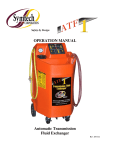
“MGR3 1” Convertible RECYCLE, EVACUATION & RECHARGE UNIT Convertible between FOUR refrigerants: R-134a, R-1234yf R-22 R-407C Unit covered under US Patent 8,082,750 and other patents pending. Certified by ITS under SAE J2911 to meet SAE J2788 for R-134a. Certified by ITS under SAE J2911 to meet high voltage compressor service per SAE 2788 for R-134a. Certified by ITS under SAE J2911 to meet SAE J2843 (Feb. 2011 Ed.) for R-1234yf. Certified by ITS under SAE J2911 to meet high voltage compressor service per SAE J2843 for R1234yf. TO COMPLY WITH SAE CERTIFICATION, THE MGR3 1 IS TO BE DEDICATED FOR USE WITH ONE REFRIGERANT. SAE CERTIFICATION DOES NOT COVER MULTIPLE REFRIGERANT USE. OPERATION MANUAL System Consists Of: • • • • • • • • • • • • “MGR3 1” Automotive Refrigerant Recover / Recycling / and Recharge Machine 6 CFM 50 micron vacuum pump Recovery Cylinder - MGR3 1 includes a 50 lb DOT storage tank. Low and High side service hoses for R-134a and R-1234yf Low and High side R-134a and R-1234yf couplings for easy conversion Removable oil injection system 3 tank refill adaptors, 1/4" SAE Female for R-134a, 1/2" ACME RH Female for R-134a, 1/2" ACME LH Female for R-1234yf R-1234yf conversion fittings for hose storage and oil flush block 41 cubic Inch SYMTECH Corporation filter drier (Replacement part number 40110342) Tank filter bracket with hardware and all tank hoses if the tank is not included 1 lb (454 gram) check weight Operation manual End user to provide: • • R-134a, R-1234yf, R-22, or R-407C refrigerant (for R-22 and R-407C refrigerant, user will need to purchase appropriate service hoses, inquire Symtech Customer Service, 888-884-8182) Refrigerant oil and/or dye for injection system Table of Contents Specifications Introduction General Safety Instructions Initial Equipment Preparation Initial Set-Up Refrigerant Conversion Operating Instructions Maintenance High Voltage Charging / Trouble Shooting Chart Warranty and Contact Information 2 3 4 5 6 7-8 9-21 22-27 30 31 MGR3 1 Specifications Model 3 MGR 1 Compressor Type 2/3 HP oil-less reciprocating compressor 29” W x 26" D x 54 H Dimensions Weight 190 lbs (does not include tank weight, or shipping pallet 10˚C (50˚F) to 49˚C (120˚F) Operating Range Power Source 115 VAC 60Hz 1Ph 100 VAC 50 / 60Hz 1Ph Power Consumption Low Side Gauge 0 to 500 PSIG Filtration 41 cubic inch drier, .7 micron oil separator Automatic Control Valves Patented motorized ball valves to control HI, LO, recover, and vacuum Charging Valve 12 VDC Solenoid Valve Heavy duty steel frame internal construction High strength rotational molded enclosure 8" wheels, rear, 4" swivel casters, front Construction 15A Thermal Breaker 15A Thermal Breaker High Pressure Shut-Off Refrigerants 220-240 VAC 50/60Hz 1Ph -30 inch Hg to 125 PSIG High Side Gauge Overload Protection 220-240 VAC 50/60Hz 1Ph 750 W 10A Thermal Breaker 30 bar (450 psig) R-134a, R-1234yf, R-22 and R-407C 2 10A Thermal Breaker INTRODUCTION Thank you for purchasing the SYMTECH Corporation, MGR3 1 Convertible series unit. The MGR3 1 has been designed to meet both R-134a and R-1234yf SAE R/R/R Standards. In accomplishing this goal, SYMTECH Corporation has integrated the latest patent pending technology and incorporated state of the art features while improving reliability and performance. The unit also meets the SAE standards for High Voltage Compressor service that many hybrid vehicles require. The MGR3 1 can also handle contaminated refrigerants with is special pump down and complete evacuation process. It gives the end user a truly one machine meets all needs. The MGR3 1 series primary use is an Automotive R/R/R unit. The MGR3 1 automatically recovers, recycles, evacuates, and recharges mobile A/C systems. Simply hook up the service hoses, choose the desired operation, and allow the unit to automatically complete the A/C service. The MGR3 1 utilizes a single pass (oil coalescing, particle filtration, and moisture removal) recycling system, which means that whenever the MGR3 1 recovers, it also recycles. The unit also incorporates automatic air purge to remove unwanted non-condensable gasses from the refrigerant. Thus the refrigerant storage tank always contains the cleanest refrigerant possible for future recharge use. The MGR3 1 utilizes patented motorized ball valves. The motorized ball valves are unique to the industry in that they will not be affected by sealants, particulates, and other contaminates. The motorized ball valves incorporate passage ways 8-15 times larger than the existing solenoid valves orifice technology. In fact the MGR3 1 uses no solenoid or check valves in the active flow path during recovery or evacuation, thus enhancing speed. The MGR3 1 utilizes patent pending two cylinder, oil-less compressor. This compressor improves reliability and performance. Being oil free, no compressor oil maintenance or oil return system is required. The following are additional features: • • • • • • • • • • • • • • • • Integrated manifold gauge set. Visually see how the mobile A/C system is operating. No manual valves to open of close Large Graphic LCD to view operating instructions. Languages include English, Spanish, French, German, Chinese and more A highly accurate electronic charge scale Microprocessor integrated mass flow system keeps track of how much refrigerant has run through the filter drier giving the user maximum amount of run time on each filter (150 LBS per filter) Cartridge type 41 inch cubic filter drier. Mounted directly on the storage cylinder for optimal moisture removal and weight accuracy Automatic high-pressure shut-off with microprocessor indication Interchangeable SYMTECH Corporation, Recovery cylinders. Use your country’s approved refrigerant cylinders. The software allows the user to set up the proper tank and refrigerant parameters. Modular design for easy replacement of a defective plumbing, scale, electronic, compressor or vacuum pump sub system Heavy-duty construction: Rotational molded outer enclosure, steel construction internal 8" rear wheels and 4” front swivel casters give this unit excellent maneuverability under the worst of conditions Recovers and Evacuates through both the high and low side service hoses Separate Vacuum pump for faster evacuations Additional service hose lengths available, 8 foot comes standard Programmed electrical outlet for optional heater blanket installation Charges on both High and Low side The MGR3 1 can easily be converted back and forth between four different refrigerants: R-134a, R-1234yf, R-22 and R-407C To help you get a good start, please continue to carefully read the balance of this manual. This manual contains important information on the proper procedures for operating this equipment. Please pay close attention to the safety information, Warnings, and Cautions provided throughout this manual. Always remember “Safety First”. Certified by Intertek under SAE J2911 to meet SAE J2788 standard for R-134a and the SAE J2788 High Voltage Compressor service provision. Certified by Intertek under SAE J2911 to meet SAE J2843 (Feb. 2011 Ed.) standard for R-1234yf and the SAE J2843 High Voltage Compressor service provision. 3 GENERAL SAFETY INSTRUCTIONS NOTE: Only qualified service personnel should operate this unit. Most states, countries, etc… may require the user to be licensed. Please check with your local government agency. DANGER- This unit’s recovery tanks contains liquid refrigerant. Overfilling of a recovery tank may cause a violent explosion resulting in severe injury or even death. Do not disable the overfill safety features. Always make sure the correct tank is on the scale. DANGER- Only use the recovery tanks provided with this unit. See distributor for replacement tanks. DANGER- Avoid breathing refrigerant v a p o r s and lubricant v a p o r or mist. Breathing high concentration levels may cause heart arrhythmia, loss of consciousness, or even cause suffocation. DANGER- Electrical shock hazard!!!! Always disconnect power source when servicing this equipment. DANGER- DO NOT USE COMPRESSED AIR TO PRESSURE TEST OR LEAK TEST THE UNIT OR VEHICLE AIRCONDITIONING SYSTEM. Some mixtures of air and R-134a refrigerant are combustible at elevated pressures. These mixtures are potentially dangerous and may result in fire or explosion causing personal injury or property damage. CAUTION- All hoses may contain liquid refrigerant u n d e r pressure. Contact with refrigerant m a y cause frostbite, o r other related injuries. Wear proper personal protective equipment such as safety goggles and gloves. When disconnecting any hose, please use extreme caution. CAUTION- Avoid breathing refrigerant v a p o r s and/or lubricant m ist . Exposure may irritate eyes, nose, throat, and skin. Please read the manufacturers Material Safety Data Sheet for further safety information on refrigerants and lubricants. CAUTION- Do not use this equipment in the vicinity of spilled or open containers of gasoline or other flammable substances. Make certain that all safety devices are functioning properly before operating the equipment. CAUTION- To reduce the risk of fire, avoid the use of extension cords thinner than NO. 16 awg. (1,5mm²). The following table references extension cord wire size vs. maximum length: WIRE GAUGE 16 14 12 MAXIMUM LENGTH (feet) 10 25 50 CAUTION- Do not operate this equipment in the vicinity of spilled or open containers of gasoline or other flammable substances. Make certain that all safety devices are functioning properly before operating the equipment. CAUTION- This equipment should be used in locations with mechanical ventilation that provides as least 4 air changes per hour. CAUTION- RISK OF INJURY, the equipment should only be operated by certified personnel. CAUTION- Use only SYMTECH Corporation certified hose assemblies on this unit. The hose assemblies are made to proper length, contain shut offs where required and have direct affect on the proper operation of this equipment. CAUTION- R-1234yf is a Class A2L flammable refrigerant. Use in well ventilated areas. Minimize leakage from the unit. Periodically check unit for leaks. 4 INITIAL EQUIPMENT PREPARATION Models MGR3 1 Will come with a 50 lb DOT tank and filter assembly pre-mounted on the rear of the machine. Please follow the instructions for initial equipment preparation: 1. Carefully unpack the unit and its contents from its shipping pallet. 2. Remove the tank and filter from on top of machine, open access door on rear of system and place tank on top and middle of scale, making sure that tank is free standing and the arrow (b) on the filter is facing left (figure 2a). FIGURE - 2a Filter bracket placed on tank collar a 3. Ensure all of the hose connections are firmly hand tight as they may have loosened during shipping. a b FIGURE – 2b Hose routing between filter, tank, and unit Contents of the accessory box: 1 Power cord 2 R-134a refill hoses, 1/4˝ SAE and 1/2˝ ACME 1 Set of R-1234yf hose holder fittings and caps 1 R-1234yf refill hose-1/2˝ ACME left hand thread 1 1 lb check weight 1 R-1234yf ID tank label 1. R-134a ID tank label The following are instructions for attachment of filter and tank hoses. FIGURE - 2b Filter placed on filter bracket 1. Check the Velcro straps that secure the filter (figure a, a) to assure of a snug attachment. a 2. Install the refrigerant tank and filter hoses as shown in Figure 2b. Connect the yellow liquid feed hose/hybrid adapter which comes from the machine to the filter port (a). Connect the yellow tank liquid hose from the tank liquid port (d) to the filter port (b). Connect the blue discharge hose coming from the machine to the vapor port (c) on the tank. Finally connect the ground wire (e) to the tank as shown in Figure - 2b. If there is not a brass fitting on your particular tank, any unpainted surface on the tank itself will suffice. b c d e 2. Attach tank hold down strap (f), CAUTION, strap should be loosely placed around tank valve guard and attached, a strap that is tightened too taut will negatively affect the gas capacity readings. f Tank hold down strap is provided to prevent tank from tilting off of scale during movement around shop area. 5 MGR3 1 INITIAL SET-UP The MGR3 1 is shipped from the factory in the R-134a SAE configuration. As indicated in our literature, the MGR3 1 can be set up for multiple refrigerants. The following instructions will guide you through the initial set up of the unit that allows changes to operational software, language, units of measure and refrigerant. Before we power the unit, it will be necessary to check the vacuum pump oil sight glass for the correct level. The vacuum pump is pre-filled at the factory. Make sure the vacuum pump power switch is in the ON position. Also check the hose connecting to the vacuum pump is tight. Open all tank and hose valves on the back of the unit. Plug the unit into the proper voltage power supply. Check the nameplate of the unit if there are any questions on power supply requirements. While holding down the Key #3, push the momentary ON-OFF switch on the touch pad control panel of the unit until the LCD lights up. The LCD comes up with SETUP MODE screen asking for SAE or NON-USA. SETUP MODE Key 3 SAE > NON-USA > FIGURE - 5 SAE applies to USA use. NON-USA would be used for anywhere outside of the USA. Keep in mind the operation of the unit is slightly different depending o n which mode you use. Push either the SAE or NON-USA key for selection. Now the language selection screen will appear. SELECT DEFAULT LANGUAGE ENGLISH > LBS > ESPAÑOL > LBS : OZ > DEUTSCH > SELECT KGS > DEFAULT UNITS OF WEIGHT GRAMS > FRANCOIS > NEXT > OZ > Push the key next to the desired language. The LCD will now show SELECT DEFAULT UNITS OF WEIGHT. Push the weight measurement system you are most likely to use. Note: That during any Charge or Full Cycle operation, the UNIT OF WEIGHT can be temporarily changed. The unit will proceed to the automatic PT (Pressure Transducer) calibration and then (if required) the air purge. This should only take a few minutes and once complete the Main Menu will appear on the LCD. RECOVER > MGR3 1 is now ready for R-134a operation. EVACUATE > SELECT MODE If the unit is being setup for a different refrigerant than R134a, go to MGR3 1 Change Initial Refrigerant setting on pages 7-8. CHARGE > FULL CYCLE > If the unit will be used for R-134a, place the R-134a ID tank label on the storage tank. Then go to page 20 to fill the recovery tank with R-134a. TANK REFILL > 6 MGR3 1 CHANGE INITIAL REFRIGERANT SETTINGS The following instructions are to be used to change the initial default refrigerant from R-134a to either R-1234yf, R-22, or R-407C. To change the refrigerant after the unit has already been put into service, see Maintenance Section on page 25. If the unit is ON, turn it OFF. Then while holding down the Key #2, push the momentary ON-OFF switch on the touch pad control panel of the unit until the LCD lights up. The LCD will come up in the Maintenance Mode. Push the CHANGE REF key. CHANGE FILTER > Key 2 SCALE > MAINTENANCE SELECT MODE PT ZERO > CHANGE REF > QUIT > MAINTENANCE MODE The LCD will have a list of refrigerants. Push the Key next to the refrigerant selection. R-134a > R-1234yf > SELECT REFRIGERANT Ball valve on the Red hose (Valve 1) going to the filter outlet. R-22 > Ball valve on the Blue tank vapor hose (Valve 2). R-407C > QUIT > The LCD will show a message to CLOSE VALVE 1. Then push the CONTINUE key. The compressor w i l l run for about 1 minute. HI and LO gauges will pull into a slight vacuum. The LCD will show a message to CLOSE VALVE 2. Then push the CONTINUE key. The vacuum pump will run for about 3-5 minutes. HI and LO gauges will pull into a deep vacuum. Once done the LCD will read CHANGE TANK & HOSE. CLOSE VALVE 1 CLOSE VALVE 2 THEN PRESS CONTINUE THEN PRESS CONTINUE CONTINUE > CONTINUE > 7 MGR3 1 CHANGE INITIAL REFRIGERANT SETTINGS Since this is the initial setup, the tank/filter assembly is empty and does not need to be changed. If the refrigerant selection is R-1234yf, place the R-1234yf ID label on the tank. If R-22 or R-407C, use a permanent marker to identify the tank. The unit comes pre-fitted with R-134a service hoses attached to the machine, R-1234yf service hoses are provided in the accompanying accessory box. • For R-22 or R-407C refrigerant selection, purchase SYMTECH Corporation hoses, inquire Symtech customer Service, 888-884-8182 NOTE: Before changing hoses, make sure MGR3 1 is disconnected from 115V power source 1. Unlock latch located on front of MGR3 1 and lift lid. 2. Locate connection point of hoses inside machine and disconnect, noting color location of hoses. 3. Remove existing hoses by threading through grommets located on lid. 4. Install the correct service hoses for the refrigerant selected by threading hoses through grommets on lid and connecting to appropriate inside connections. 5. Close and lock cabinet lid. NOTE: The following are additional tasks to complete the R-1234yf conversion: 1. Close all tank and hose valves to prevent loss of vacuum. Replace the R-134a service nipples on the hybrid vehicle flush block hose assembly with the provided R-1234yf service nipples. The hybrid vehicle flush block is integrated into the Red hose that connects from the back of the unit to the filter out connection. Once done, open all tank and hose valves. 2. Replace the R-134a storage nipples on the unit’s handle with the provided R-1234yf storage nipples. Push the CONTINUE key. The unit will proceed to do the automatic PT (Pressure Transducer) calibration and then (if required) the air purge. This should only take a few minutes and once complete the Main Menu will appear on the LCD. CHANGE TANK & HOSE RECOVER > THEN PRESS CONTINUE EVACUATE > SELECT MODE CHARGE > *FULL CYCLE > CONTINUE > TANK REFILL > *If the unit is setup for R-1234yf SAE configuration, the FULL CYCLE mode will not show up in the main menu. It will be necessary to fill the storage tank with the assigned refrigerant in order to run recharge an AC system. The unit can perform recovery operations at this time, but cannot charge. Go to the TANK REFILL mode instructions on page 20 to add refrigerant to the tank. Initial setup is now complete. Read the balance of this manual for complete operating and maintenance instructions. 8 OPERATING INSTRUCTIONS FOR THE MGR3 1 IMPORTANT: BEFORE USING THIS START UP GUIDE IT IS HIGHLY RECOMMENDED THAT THE USER COMPLETELY READ AND UNDERSTAND THIS ENTIRE MANUAL. FAILURE TO OPERATE AS SPECIFIED COULD RESULT IN DAMAGE TO THE UNIT, WHICH COULD ALSO LEAD TO LOSS OF WARRANTY. The MGR3 1 is a microprocessor driven unit. The operating instructions are contained on the LCD. Simply choose the desired function of the unit and follow the directions on the LCD. The following are the basic instructions on safely operating each function of this unit. Operating Instructions Open all Storage Tank Valves. Push the momentary Power switch to (ON). The unit will run a brief diagnostic routine. LCD will read: RE-Zeroing PT, Please wait. Once done with PT calibration process, the unit will proceed to the automatic air purge sequence. This will take up to 3 minutes. RE-ZEROING P. TRANSDUCER AUTOMATIC AIR PURGE PLEASE WAIT PLEASE WAIT RECOVER > EVACUATE > The LCD screen should now read: This is called the MAIN MENU. SELECT MODE CHARGE > *FULL CYCLE > TANK REFILL > • Connect the refrigerant service hoses to the automobile A/C system to be serviced. • Open the High and Low side service couplers. Push the KEY for the desired mode. The different modes are as follows: 1. Recover 2. Evacuation (Vacuum) 3. Charge 4. Full cycle 5. Tank refill Follow the directions on the LCD for each mode. The following pages will discuss the operation of each mode in detail. *If the unit is setup for SAE R-1234yf operation full cycle will not show up on the LCD. 9 OPERATING INSTRUCTIONS (Continued) RECOVER / RECYCLE MODE: The Recover/Recycle mode would be chosen to recovery refrigerant from an Auto A/C system that needs a refrigerant containing component replaced such as a compressor, evaporator, orifice tube, condenser, etc…. IMPORTANT: Before starting the recovery of the refrigerant, a refrigerant identifier should be used to to determine the type and purity of the refrigerant. Failure to properly identify the refrigerant could potentially expose the user to danger from flammable refrigerants and health hazards from toxic refrigerants. Cross contamination of refrigerants can also occur and would require special handling of the refrigerant. From the Main Menu screen, Push the RECOVER key. The LCD will now read: Push the START key. MAKE CERTAIN HOSES ARE CONNECTED AND VALVES ARE OPENED. THEN PRESS [START] RECOVER > EVACUATE > SELECT MODE CHARGE > *TANK CAPACITY REMAINING FULL CYCLE > START > 26.00 LBS QUIT > TANK REFILL > When the MGR3 1 reaches approximately 20" hg. vacuum. The LCD will now read. The MGR3 1 will proceed to drain the recovered oil: The LCD will now read: The MGR3 1 is now recovering refrigerant. The LCD will show the amount of refrigerant recovered. RECOVERY IN PROGRESS, PLEASE WAIT RECOVERY COMPLETE RECOVERED 1.00 LBS RECOVERED 2.00 LBS TANK CAPACITY REMAINING 25.00 LBS DRAINING OIL 00:00:45 PLEASE WAIT QUIT > QUIT > Record the RECOVERED weight reading on the LCD. Push the QUIT key to return to Main Menu (as shown below) or PROCEED TO EVACUATE key for evacuation operation. Do not forget to measure the A/C oil in the oil drain bottle for future A/C oil re-injection. RECOVER/RECYCLE Operation i s now complete. RECOVER > RECOVERY COMPLETE EVACUATE > RECOVERED 2.00 LBS SELECT MODE CHARGE > TO VACUUM > FULL CYCLE > QUIT > TANK REFILL > * TANK CAPACITY REMAINING - is the amount of space available in storage tank. 10 OPERATING INSTRUCTIONS (Continued) EVACUATE MODE: The EVACUATE Mode would be chosen to remove air and moisture from an Automobile A/C system that has been open to the atmosphere. CAUTION: Air and moisture in an A/C system can cause premature failure of A/C system components. The LCD will now read: Push the + or – ARROW keys until the desired vacuum time is programmed. Once done, push the START key. From the Main Menu screen, Push the EVACUATE Key SET EVACUATION TIME RECOVER > EVACUATE > SELECT MODE TIME + > TIME - >00:10:00 CHARGE > FULL CYCLE > START > TANK REFILL > QUIT > The LCD will now read: The vacuum pump will run until the TIME REMAINING reaches 00:00 The unit will then proceed to a 2:00 minute leak check test. The LCD will now read: EVACUATION IN PROGRESS LEAK CHECK IN PROGRESS TIME REMAINING 00:00:00 TIME REMAINING 00:02:00 PLEASE WAIT QUIT > SKIP > If leak check fails, check A/C system for leaks. If leak check passes The LCD will now read: Push the QUIT key to return to Main Menu or CHARGE key for charge operation. RECOVER > EVACUATE > EVACUATION COMPLETE SELECT MODE CHARGE > CHARGE > FULL CYCLE > QUIT > TANK REFILL > NOTE: If a leak is detected, the LCD will be prompted. 11 OPERATING INSTRUCTIONS (Continued) CHARGE MODE: The CHARGE mode would b e chosen to recharge a mobile A/C system after it has been properly evacuated. This is also the time to inject oil back into the A/C system. See special instructions on page 27 for High Voltage Compressor A/C system charging. For units configured for R-1234yf in the SAE mode, go to page 17 for CHARGE MODE instructions. The LCD will now read: Select which service hose unit should charge through. It is recommended to use HIGH SIDE charging to prevent compressor slugging. From the Main Menu screen, Push the CHARGE key. SELECT MODE RECOVER > LOW SIDE > EVACUATE > HIGH SIDE > CHARGE > BOTH > TANK REFILL > The LCD will now read: If desired, the units of measure can be changed at this time. Push the CHANGE UNITS key. If the CHANGE UNITS key is pushed, the LCD will read: Select units of measure. CHARGE + > LBS > CHARGE - > LBS : OZ > SELECT UNITS OF MEASURE CHANGE UNITS > KGS > START > GRAMS > QUIT > OZ > Oil Injection System The LCD will now read: Open the oil injection valve until the desired amount is dispensed. Push CONTINUE key once oil injection is complete. Continue by pushing the + or - ARROW key until the charge amount is programmed. Once desired amount is programmed, push the START key. CHARGE + > CHARGE SELECTED 2.00 LBS CHARGE - > IF REQUIRED INJECT OIL AT THIS TIME CHANGE UNITS > * AVAILABLE REF. 24.00 LBS START > CONTINUE > QUIT > QUIT > * AVAILABLE REF. This is the amount of refrigerant available for charging. If this drops below zero, charging will not start. 12 OPERATING INSTRUCTIONS (Continued) The LCD will now read: The CHARGE DISPENSED reading will begin to increase. Note: If the unit does not completely dispense the charge into the A/C system, the LCD will notify the user of options to complete the charge. Once the CHARGE DISPENSED equals the CHARGE. The LCD will read: Close HIGH SIDE COUPLER. Push CONTINUE key CLOSE HIGH SIDE COUPLER CHARGE SELECTED 2.00 LBS CHARGE DISPENSED 0.00 LBS QUIT > CONTINUE > Start car A/C system, Push CONTINUE key. PLEASE WAIT... START CAR A/C SYSTEM CONTINUE > Charge is now complete. Push QUIT key to return to MAIN MENU CHARGING COMPLETE CHARGE SELECTED 2.00 LBS CHARGE DISPENSED 2.00 LBS QUIT > 13 OPERATING INSTRUCTIONS (Continued) FULL CYCLE: The fully automatic mode is commonly used at quick car care service facilities where no leaks or repairs are required, but the A/C system seems to be undercharged. Full cycle is not available on R-1234yf SAE mode. IMPORTANT: Before starting the recovery of the refrigerant, a refrigerant identifier should be used to determine the type and purity of the refrigerant. Failure to properly identify the refrigerant could potentially expose the user to danger from flammable refrigerants and health hazards from toxic refrigerants. Cross contamination of refrigerants can also occur and would require special handling of the refrigerant. The LCD will now read: Push the + or - ARROW keys until the desired vacuum time is programmed. Push the NEXT key. From the MAIN MENU screen, Push the FULL CYCLE key. SET EVACUATION TIME RECOVER > EVACUATE > SELECT MODE TIME + > 00:05:00 CHARGE > TIME - > FULL CYCLE > NEXT > TANK REFILL > QUIT > The LCD will now read: If oil injection is required, push the YES key. Otherwise push the NO key. If the YES key is pushed, you will be notified when to inject the oil. The LCD will now read: If desired, the units of measure can be changed at this time. Push the CHANGE UNITS key. OIL INJECTION? CHARGE + > CHARGE SELECTED 2.00 LBS CHARGE - > CHANGE UNITS > * AVAILABLE REF. 24.00 LBS YES > NO > START > QUIT > 14 OPERATING INSTRUCTIONS (Continued) The LCD will now read: Continue by pushing the + or - ARROW key until the charge amount is programmed. Once desired amount is programmed, push the START key If the CHANGE UNITS key is pushed, the LCD will read: Select units of measure. LBS > CHARGE + > CHARGE SELECTED 2.00 LBS LBS : OZ > SELECT UNITS OF MEASURE KGS > CHARGE - > CHANGE UNITS > * AVAILABLE REF. 24.00 LBS GRAMS > START > OZ > QUIT > When the MGR3 1 reaches the required vacuum level, the unit will proceed to drain the recovered oil: The LCD will now read: The LCD will now read: The MGR3 1 is now recovering refrigerant. The LCD will show the amount of refrigerant recovered. RECOVERY IN PROGRESS, PLEASE WAIT RECOVERY COMPLETE RECOVERED 1.00 LBS RECOVERED 2.00 LBS TANK CAPACITY REAMAINING 25.00 LBS DRAINING OIL 00:00:45 PLEASE WAIT QUIT > QUIT > * AVAILABLE REF. This is the amount of refrigerant available for charging. If this drops below zero, charging will not start. * TANK CAPACITY REMAINING - is the amount of space available in storage tank. The unit will proceed to a 2:00 minute leak check test. The LCD will now read: Note: If leak check fails, check A/C system for leaks. The FULL CYCLE process will be aborted. Once DRAINING OIL is complete, the unit will proceed to Evacuation. The vacuum pump will run until the TIME REMAINING reaches 00:00. The LCD will now read: EVACUATION IN PROGRESS LEAK CHECK IN PROGRESS TIME TIME REMAINING 00:00:00 TIME TIME REMAINING 00:20:00 PLEASE WAIT QUIT > SKIP > 15 OPERATING INSTRUCTIONS (Continued) The LCD will now read: The CHARGE DISPENSED reading will begin to increase. Note: If the unit does not completely dispense the charge into the A/C system, the LCD will notify the user of options to complete the charge. Once the LEAK CHECK has passed or the SKIP key is pushed, The LCD will read: Open the oil injection valve until the desired amount is dispensed. Push the CONTINUE key CHARGING CHARGE SELCTED 2.00 LBS IF REQUIRED INJECT OIL AT THIS TIME CHARGE DISPENSED 0.00 LBS CONTINUE > QUIT > QUIT > See Figure - A on page 12 for further details on the oil injection system. Once the CHARGE DISPENSED equals the CHARGE. The LCD will read: Close HIGH SIDE COUPLER. Push CONTINUE key CLOSE HIGH SIDE COUPLER CONTINUE > 16 OPERATING INSTRUCTIONS (Continued) Start car A/C system, Push CONTINUE key. PLEASE WAIT... START CAR A/C SYSTEM CONTINUE > Once the charge amount has been met, The LCD will read: Record the data on the LCD. Push the QUIT key. FULL CYCLE is complete. FULL CYCLE COMPLETE REFR. RECOVERED 2.00 LBS CHARGE SELECTED 2.00 LBS CHARGE DISPENSED 2.00 LBS QUIT > The LCD will return to the main menu. RECOVER > EVACUATE > SELECT MODE CHARGE > FULL CYCLE > TANK REFILL > 17 OPERATING INSTRUCTIONS (Continued) SAE CHARGE MODE for R-1234yf: This mode has additional leak tests that are required by SAE J2843 due to the flammable nature of R-1234yf. This mode will allow for re-injection of new oil into the A/C system. See special instructions on page 25 for High Voltage Compressor A/C system charging preparation. The LCD will now read: Select which service hose unit should charge through. It is recommended to use HIGH SIDE charging to prevent compressor slugging. From the Main Menu screen, Push the CHARGE key. SELECT MODE RECOVER > LOW SIDE > EVACUATE > HIGH SIDE > CHARGE > BOTH > TANK REFILL > The LCD will now read: If desired, the units of measure can be changed at this time. Push the CHANGE UNITS key. If the CHANGE UNITS key is pushed, the LCD will read: Select units of measure. CHARGE + > LBS > CHARGE - > LBS : OZ > SELECT UNITS OF MEASURE CHANGE UNITS > KGS > START > GRAMS > QUIT > OZ > Continue by pushing the + or - ARROW key until the charge amount The LCD will now read: The vacuum pump will turn ON and run is programmed. Once desired amount is programmed, push the from 5-10 minutes. Once the vacuum pump turns off, the unit START key. goes into a 5 minute vacuum hold test. CHARGE + > CHARGE SELECTED 2.00 LBS LEAK CHECK IN PROGRESS CHARGE - > CHANGE UNITS > * AVAILABLE REF. 24.00 LBS START > QUIT > -14.5 PSIG 18 If the unit passes the vacuum hold test, it will proceed into a pressurized leak test. This is noted by the rise in the pressure reading on the LCD. If it fails, find and repair leak and rerun CHARGE MODE. If the unit passes the pressure test the LCD will read: The LCD will now read: The unit will change 15% of the program charge into the A/C system. Once stabilized, the unit will begin a pressure decay test. At this time it is recommended to use an electronic leak detector as an additional check. This process will take approximately 5 minutes. The compressor will start to recover the 15% test charge. If the unit fails the pressure test, find and repair leak. Rerun the CHARGE MODE. When the recovery is complete, the the vacuum pump will start and pull a deep vacuum in order to prepare the unit for final charge. This will take about 5 minutes. LEAK CHECK IN PROGRESS PREPARING FOR FINAL CHANGE 83.0 PSIG 10.0 PSIG If either the vacuum leak test or the pressure leak tests fail, the LCD will display a failure message. Either failure will prevent the software from completing the charge sequence. It will be necessary to repair the leak and repeat the CHARGE MODE. Once the evacuation sequence is complete, the unit will perform a mandatory Non-condensable gas check on the storage tank. The LCD will read: Once NCG purge is done, The LCD will now read: Open the oil inject valve until the desired amount is dispensed. Push the CONTINUE key once done. AUTOMATIC AIR PURGE IF REQUIRED INJECT OIL AT THIS TIME PLEASE WAIT... CONTINUE > QUIT > 19 OPERATING INSTRUCTIONS (Continued) The LCD will now read: The CHARGE DISPENSED reading will begin to increase. Note: If the unit does not completely dispense the charge into the A/C system, the LCD will notify the user of options to complete the charge. Once the CHARGE DISPENSED equals the CHARGE SLECTED. The LCD will read: Close HIGH SIDE COUPLER. Push CONTINUE key CLOSE HIGH SIDE COUPLER CHARGE SELECTED 2.00 LBS CHARGE DISPENSED 0.00 LBS QUIT > CONTINUE > Start car A/C system, Push CONTINUE key. PLEASE WAIT... START CAR A/C SYSTEM CONTINUE > Once complete the LCD will read: Push QUIT key to return to the MAIN MENU. The LCD will return to the main menu. CHARGING RECOVER > EVACUATE > CHARGE SELCTED 2.00 LBS SELECT MODE CHARGE DISPENSED 2.00 LBS CHARGE > FULL CYCLE > QUIT > TANK REFILL > 20 OPERATING INSTRUCTIONS (Continued) REFILL MODE: The REFILL mode would be chosen to add refrigerant to the tank for the first time or add more refrigerant to the recovery tank. This operation can be run pushing the TANK REFILL key from the Main Menu or may be prompted when insufficient refrigerant exists when in CHARGE or FULL CYCLE modes. It’s recommended to use a refrigerant identifier on the virgin supply tank to guard against counterfeit refrigerants. The LCD will now read: Connect the High Side service hose to a virgin supply tank. Push the START key. From the MAIN MENU, Push the TANK REFILL key. CONNECT HIGH SIDE SERVICE HOSE TO NEW R-134a TANK. RECOVER > EVACUATE > SELECT MODE OPEN VALVE ON TANK AND TURN IT UPSIDE DOWN. CHARGE > FULL CYCLE > START > TANK REFILL > QUIT > Note: To speed up the Refill process, turn the supply tank upside down or make sure the liquid refrigerant is being recovered. The LCD will now read: Caution: Do not turn off unit. If stoppage is required, close the HIGH SIDE COUPLER and allow the unit to complete the clearing process. If REFILLING amount reached zero, the LCD will read: Push the Quit Key to return to Main Menu. REFILLING COMPLETING TANK REFILL 20.00 LBS TO GO UNTIL TANK IS FULL PLEASE WAIT QUIT > QUIT > The unit will run until: 1. REFILLING amount on LCD reaches zero or 2. Virgin supply tank is pulled into a vacuum If Virgin supply tank is pulled into a vacuum, the LCD will read: Either add a new Virgin supply tank and push RESUME or Push the QUIT key to return to Main Menu. Pushing the QUIT key will return to the main menu. RECOVER > SUPPLY TANK EMPTY REPLACE WITH NEW TANK EVACUATE > SELECT MODE CHARGE > RESUME > FULL CYCLE > QUIT > TANK REFILL > 21 MAINTENANCE MAINTENANCE MODES: DURING NORMAL OPERATION OF MGR3 1 FILTER CHANGE: The MGR3 1 uses a mass flow tracking system on how much recovered refrigerant has passed through the Filter Drier (SYMTECH Corporation p/n ARXF5). Each 41 Cubic Inch Drier can handle 150 lbs. of refrigerant before requiring change. When it is determined that the filter has exceeded the 150 lbs., the unit locks out (if in SAE mode) the recovery function in both RECOVERY and FULL CYCLE. It is necessary to purchase a Filter Drier under SYMTECH Corporation p/n ARXF5. Each new Filter Drier comes with a unique code to unlock the recover/recycle function. The MGR3 1 has a lower tilt drawer design to hold 2 spare filters. When the Filter Life reaches 0%, the following LCD screen will come up. Push the CHANGE FILTER key to begin filter change procedure. Note: pushing QUIT key at this time will return the unit to the Main Menu. While in the SAE mode, all functions except RECOVER and FULL CYCLE are active. To unlock RECOVER and FULL CYCLE modes, complete the filter change procedure) When choosing the RECOVER or FULL CYCLE modes, the MGR3 1 will remind the user to order a filter when the FILTER LIFE REMAINING is below 25%. The following is an example of the LCD when Filter Life is less than 25%: Push the CONTINE key to proceed to filter change. RECOVERY WILL NOT BE ALLOWED WHEN FILTER LIFE EXCEEDED ORDER P/N ARXF5 FILTER LIFE EXCEEDED. RECOVERY NOT ALLOWED FILTER LIFE REMAINING 20% FILTER CHANGE > REPLACE FILTER WITH SYMTECH CORPORATION CHANGE FILTER > P/N ARXF5 CONTINUE > QUIT > The LCD will now read: Push the START key to begin Filter Change routine. FILTER CHANGE DO NOT CONNECT TO A/C SYSTEM PUSH [START] START > QUIT > The LCD will now read: The evacuation process will take about 2-5 minutes. The unit will run until a filter has been evacuated. The LCD will now read: After closing liquid port tank valve, push CONTINUE key CLOSE LIQUID PORT VALVE ON RECOVERY TANK FILTER CHANGE EVACUATING FILTER THEN PRESS CONTINUE PLEASE WAIT CONTINUE > QUIT > 22 MAINTENANCE AUTOMATICALLY OCCURING DURING THE OPERATION OF THE UNIT FILTER CHANGE (continued): LCD will now read: Use the +,-, KEYS to fill in the filter code for each blank. Use the <,> KEYS to move cursor to the next blank See filter label for code.. Once the filter has been evacuated, the LCD will read: Replace the filter with new ARXF5. Then Push the NEXT key: UP + FILTER CHANGE ENTER FILTER ID DOWN - REPLACE FILTER USE + - < > KEYS ORDER P/N ARXF5 PUSH [NEXT] ________ RIGHT > LEFT < PUSH [ENTER] NEXT > ENTER The LCD will now read: Filter Change is now complete. Push the QUIT key to return to MAIN MENU. Push the ENTER key once the entire code is shown on LCD. UP + ENTER FILTER ID FILTER REPLACEMENT COMPLETE RE-OPEN TANK LIQUID VALVE PUSH [QUIT] DOWN USE + - < > KEYS RIGHT > _ 1_ 2_ 3 _4 _5 _6 _7 _8 FILTER LIFE REMAINING: 100% LEFT < PUSH [ENTER] QUIT > ENTER VACUUM OIL CHECK: Every 10 hours of vacuum pump run time the following message will appear in EVACUATION or FULL CYCLE modes. The oil level can be seen through the sight glass of the vacuum pump. To change the oil, first loosen the wing nut under the frame and then slide the vacuum pump out. The vacuum pump oil should be clear, use SYMTECH Corporation vacuum pump oil p/n, 40110350. Make sure the oil level is up to the fill mark on the oil sight glass. Push CONTINUE key to proceed to the EVACUATION or FULL CYCLE modes. CHECK VACUUM PUMP OIL 10 hrs. OF RUN TIME HAVE ELAPSED SINCE LAST OIL CHANGE PLEASE CHANGE OIL THEN PRESS [CONTINUE] CONTINUE > Automatic Non-condensable Gases (NCG) Purge: Upon start up of the unit, the NCG purge will begin automatically. If the compressor was recently run, it could take up to 30 minutes before the NCG routine is allowed to run. To perform this operation, simply turn the unit off and back on. In the SAE MODE for R-1234yf, the NCG purge cycle will operate just before charging. 23 MAINTENANCE MAINTENANCE VIA KEYPAD OPERATION To enter into the units MAINTENANCE mode, hold down Key 2 and then turn power switch on. The LCD will now read: FILTER CHANGE: Push the CHANGE FILTER key. Go to page 21 for detailed FILTER CHANGE instructions. CHANGE FILTER > Key 2 SCALE > MAINTENANCE SELECT MODE PT ZERO > CHANGE REF > QUIT > MAINTENANCE MODE The LCD will now read: Place Calibration Weight on tank. Push the YES key if weight reading matches Calibration weight. (Push the NO key if weight does not match. See service manual for complete scale re-calibration procedure. A 25LB or 15KG Class F weight will be required for scale re-calibration.) SCALE CHECK: Push the SCALE key. The LCD will now read: Push the YES key to proceed with accuracy check. Pushing the NO key will skip the accuracy check and proceed to the Re-Zeroing function. CHECK SCALE ACCURACY? PLACE CALIBRATION WEIGHT ON SCALE DOES READING MATCH CALIBRATION WEIGHT? YES > YES > 0g NO > NO > The LCD will now read: Push the YES key to proceed with RE-ZERO scale. Note: Pushing the NO key will prompt the unit to reboot and Go to MAIN MENU LCD will now read: Lift the Tank off the scale. Then Push NEXT key. SCALE RE-ZERO FUNCTION? REMOVE TANK FROM SCALE PLATFORM CURRENT SCALE WEIGHT 0g PUSH [NEXT] YES > NEXT > NO > QUIT > 24 MAINTENANCE The LCD will now read: Push the YES key if CURRENT SCALE WEIGHT is zero. The unit will re-boot and go to the MAIN MENU. Pushing the NO key will repeat Re-Zeroing process. The LCD will now read: Wait until the LCD screen changes. TARE OPERATION COMPLETE RE-ZEROING SCALE WEIGHT - 0 ? PLEASE WAIT CURRENT SCALE WEIGHT g YES > NO > NOTE: Keep tank off scale platform NOTE: Once complete place tank back on scale platform PT SENSOR/GAUGES: Push the PT SENSOR key. The MGR3 1 will begin a automatic routine to recalibrate the Pressure Transducer (PT) The LCD will now read: Wait for Re-zeroing procedure to complete. CHANGE FILTER > SCALE > MAINTENANCE SELECT MODE RE-ZEROING P. TRANSDUCER PT ZERO > PLEASE WAIT QUIT > 0.1 PSI The Pressure Transducer (PT) calibration will automatically complete the procedure. Once done, the LCD will return to the Main Menu: RECOVER > EVACUATE > SELECT MODE CHARGE > FULL CYCLE > TANK REFILL > 25 MAINTENANCE CHANGE REFRIGERANT: The LCD will have a list of refrigerants. Push the key next to the refrigerant for selection. Push the CHANGE REF key CHANGE FILTER > R-134a > SCALE > R-1234yf > MAINTENANCE SELECT MODE SELECT REFRIGERANT PT ZERO > R-22 > CHANGE REF > R-407C > QUIT > QUIT > The LCD will show a message to CLOSE VALVE 1. Then push the CONTINUE key. The compressor will run for about 1 minute. HI and LO gauges will pull into a slight vacuum. CLOSE VALVE 1 THEN PRESS CONTINUE Ball valve on the Red hose (Valve 1) going to the filter outlet. Ball valve on the Blue tank vapor hose (Valve 2). CONTINUE > The LCD will show a message to CLOSE VALVE 2. Then push the CONTINUE key. The vacuum pump will run for about 3-5 minutes. HI and LO gauges will pull into a deep vacuum. Once done the LCD will read CHANGE TANK & HOSE. CLOSE VALVE 2 CHANGE TANK & HOSE THEN PRESS CONTINUE THEN PRESS CONTINUE CONTINUE > CONTINUE > 26 MAINTENANCE CHANGE REFRIGERANT (continued): • The unit comes with the R-1234yf service hoses. For R-22 or R-407C refrigerant selection, purchase SYMTECH Corporation hoses, inquire Symtech customer Service, 888-884-8182 NOTE: Before changing tank/filter/hose assembly, make sure MGR3 1 is disconnected from 115V power source 1. 2. 3. 4. 5. 6. 7. Unlock latch located on front of MGR 3 1 and lift lid. Locate connection point of tank hoses inside machine and disconnect, noting color location of hoses. Install the correct service hoses for the refrigerant selected by connecting to appropriate inside connections. Close and lock cabinet lid. Unlock door on back of unit and open door. Disconnects ground wire (green) from tank. Remove entire tank/filter/hose assembly from back of unit. NOTE: It will be necessary to use Symtech Corporation Kit 40110301 (50# Tank Kit) for additional refrigerants. 8. Place either new or existing 50# tank/filter/hose assembly on scale platform. Connect the tank Red hose to upper bulk head fitting. Connect Blue tank hose to lower bulk head fitting. Reconnect ground wire clamp to tank Once refrigerant change has been completed. Push the CONTINUE key. The unit will proceed to do the automatic PT (Pressure Transducer) calibration and then (if required) the air purge. This should only take a few minutes and once complete the Main Menu will appear on the LCD. If there are any questions on confirming the refrigerant selected, turn OFF the unit. Then turn the unit ON. The LCD will briefly show the current refrigerant selected. The LCD will have a list of refrigerants. Push the Key next to the refrigerant selection. R-134a > R-1234yf > SELECT REFRIGERANT R-22 > R-407C > QUIT > Maintenance - Interconnecting Hoses, Service Hoses and Couplers: The MGR3 1 uses brass to brass seal type fitting on the ends of the service hoses and interconnecting hoses. No hose gasket maintenance is required on brass to brass type connections. The fittings connecting to the filter drier do use a rubber hose gasket. When changing the filter drier, check the gaskets for wear. Replace if required. Periodically inspect all refrigerant hose assemblies, service hoses and both service coupler inner o-rings for wear. Replace the component(s) if excessive wear or leakage is observed. Periodically leak-check all hose connection points, hose ball valves, and service couplers. Since the unit does pull a vacuum in the recovery process, excessive Non-Condensable Gases (NCG’s) could be sucked into the system and placed in the storage tank. 27 SERVICE PARTS AND ACCESSORIES Item Description 4011 Oil Injection Bottle 40110342 Coded 41 cu in filter 40110340 Oil injection assembly 40110341 115 volt 300 watt heater blanket 40110322 HFO-1234yf Low side coupler (12mm) 40110323 HFO-1234yf High side service coupler (12mm) 40110330 R-134A High side coupler 40110331 R-134A Low side coupler 40110350 Premium vacuum pump oil,12 quart case 4011 1lb. check weight 4011 15 AMP breaker 115 VAC 4011 4011 ON / OFF momentary switch 4011 6 ft. power cord 115 VAC HIGH VOLTAGE A/C CHARGING INSTRUCTIONS OEM manufacturers of Automotive High Voltage A/C systems have required that the residual amount of PAG oil in the charging hose(s) be reduced to a minimal level. The following are instructions on how to prepare the MGR3 1 for charging a High Voltage A/C system: Step 1: Remove the oil injection assembly from the MGR3 1 injection port. Cap off this port. Step 2: Push the REFILL key. Do not hook up the service hoses as a instructed by the LCD. Step 3: Push the START key. Run until RESUME and QUIT keys come up on the LCD. b Step 4: Connect both HI and LO service hoses to the auxiliary fittings (a-b) on the hose between the filter and tank liquid port as shown in Fig 3. Step 5: Step 6: Step 8: Step 9: Push the RESUME key. Open both HI and LO service coupler valves. Step 7: Run for 30 minutes. After 30 minutes close both HI and LO couplers. Allow the REFILL mode to complete the evacuation of the hoses. Connect service hoses to auxiliary ports on the liquid feed hose. The unit is now ready to charge a High Voltage A/C system. Following the CHARGING MODE instructions on page 13 or 18 (R-1234yf SAE MODE). NOTE: When injecting oil back into a high voltage A/C system, use the OEM recommended oil. Purchase SYMTECH CORPORATION injecting kit P/N # 40110340 for additional injectors for different OEM oils. TROUBLE SHOOTING Problem: High Pressure Limit. Solution: Check that both Storage Tank valves are open. Check that any inline hose ball valves to the Storage Tank are open. Problem: Tank Overfill. Solution: Remove refrigerant from Storage Tank by charging into an empty refrigerant cylinder. If this does not fix the problem, then Re-Zero scale. Problem: Unit not charging accurately. Solution: Make sure Storage Tank is properly placed on platform so that no portion of the tank is touching the back of the unit or protective frame work of the unit. Solution: Do not move the unit while in the charging mode. The unit utilizes a weighing method of charging. Sudden movement of the storage tank will affect the charging accuracy. Solution: Make sure unit is on a level surface. If placed on surface with more than 2% grade, the charging amount may be incorrect. Problem: Unit will not power up. Solution: Check to make sure circuit breaker on back of unit is not tripped. Reset and restart the unit if necessary. Solution: Make sure power cord is plugged into the back of the unit and the wall receptacle. Problem: Upon compressor start up, the circuit breaker trips. Solution: Reset circuit breaker and try again. Problem: Upon vacuum pump start up, the circuit breaker trips. Solution: Check Oil Level in vacuum pump. Reset circuit breaker and try again. Solution: Make sure vacuum pump voltage switch is in the correct position. For other questions of operation, please call: SYMTECH Corporation Service network for further instructions. 888-884-8182 WARRANTY & REPAIR POLICY / CONTACT INFORMATION WARRANTY / REPAIR OLICY SYMTECH Corporation guarantees that the MGR3 1 is free of manufacturing and material defects for one year. If a component should fail during the guarantee period, it will be repaired or replaced (at our option) at no charge. This guarantee does not apply to components that have been altered, misused, or returned solely in need of field service maintenance. This repair policy does not include components that are determined to be beyond economical repair. A component being returned for warranty repair must be accompanied by an original bill of sale and customer contact information. SYMTECH Corporation 524 S. E. Transport Drive Lee’s Summit, Missouri 64081 816-525-9263 Fax: 816-525-9283 888-884-8182 [email protected] Website: www.Symtechcorp.net Version: 7202013-1