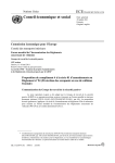
1
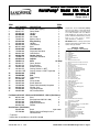
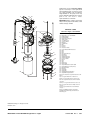
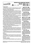
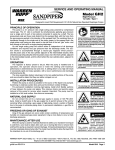
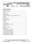
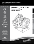
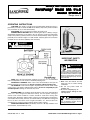
SER
VICE AND OPERA
TING MANUAL
SERVICE
OPERATING
Por
taPump® Model SP
A 1½-E
ortaPump
SPA
Model SP
A40-E
SPA40-E
Design Level 3
OPERATING INSTRUCTIONS
THE PUMP: This pump is a totally enclosed, submersible dewatering unit. It is
powered by a 1/3 HP, 12 volt DC 30 AMP motor. Battery clips on the power cord allow
easy connection to any 12 volt vehicle battery.
SWITCHING: The on-off switch is located on the power cord.
CONNECTING TO BATTERY: When connecting the clips to a battery, arcing is
eliminated by keeping the on-off switch in the "off" position. Connect the red battery
clamp to the positive (+) battery terminal. Connect the black battery clamp to ground:
preferably on the vehicle’s engine to a solid, metallic, stationary point. The connection
should be at least 18 inches (480mm) from the battery.
DANGER
Turn off before connecting battery
clamps to battery. Arcing could result.
IMPORTANT SAFETY
INFORMATION
IMPORTANT
Read these safety warnings
and instructions in this
manual completely, before
installation and start-up of the pump. It is
the responsibility of the purchaser to retain
this manual for reference. Failure to comply
with the recommendations stated in this
manual will damage the pump, and void
factory warranty.
HOSE: Since the pump develops relatively low pressure, it is recommended
that non-collapsible hose be used for maximum pumping rates.
HOISTING & LOWERING: Attach a line to the metal handle on the top of the
pump for hoisting or lowering the unit. Do not use power cable for handling unit.
TO OPERATE: Lower unit into liquid to be pumped and activate switch. Pump
can be run for a few minutes without liquid, however, do not run completely dry for
extended periods. Damage to shaft seal may result.
RUNNING TIME: This unit draws about 30 amperes and can be operated about
1hour on a fully charged 55 AMP-hour battery and still permit starting of
vehicle under normal conditions. Caution should be used when running time
exceeds 30 or 40 minutes without engine running to recharge battery, particularly in
cold weather when battery efficiency is lowered. Battery size (AMP-hour rating) and
the use of other accessories such as lights and radios, etc., must be taken into
consideration for practical running periods without engine running.
OVERLOAD PROTECTION is provided by means of a 40 amp automatic reset
circuit breaker, located under top cover.
1. Make sure the vehicle and the
pump are not in contact during
connection.
2. Do not use power cable for
handling unit.
3. Do not run completely dry for
extended periods. Damage to shaft
seal may result.
DANGER
DANGER: Not for use with fluids
that have a flash point below 100°
F (38° C) [examples: gasoline, alcohol.]
Sparking could result in death.
WARREN RUPP, INC., A unit of IDEX Corporation • 800 N. Main Street • Mansfield, OH 44902 USA • (419) 524-8388 Fax (419) 522-7867
520-001-000 Rev C
6/05
Model SPA1½-E and SPA40-E Design Level 3 Page 1
TROUBLE SHOOTING
NOTE: Most common cause of failure to run is due to hardened mud and sand at
impeller. Remove strainer to check.
MOTOR WILL NOT RUN:
1. Poor connection at battery.
2. Impeller locked with foreign material.
3. Insufficient impeller clearance.
4. Damaged power cable or loose connection internally in motor assembly.
5. Bad switch or circuit breaker. Connect power leads direct to motor leads to check.
6. Worn motor brushes or out of position to make contact with armature.
PERFORMANCE LOW:
1. Strainer screen partially plugged.
2. Impeller rubbing. Check freeness of rotation with screwdriver inserted through
hole in base plated into slotted end of shaft.
3. Battery not fully charged.
4. Discharge restriction such as kinked hose or excessive discharge head.
Motor runs backwards:
1. Check wiring for correct polarity.
IMPORTANT
Should unit not operate,
always check freeness of
rotation of impeller by inserting
screwdriver through hole in base
plate into slot in end of shaft.
SERVICE AND REPAIR INSTRUCTION
DISASSEMBLY: Impeller and shaft seal can be inspected and serviced from
lower end of pump by removal of 4 capscrews securing base plate, strainer screen,
and suction cover. Screwdriver slot is provided in end of motor shaft to turn shaft while
holding impeller for removal. This permits removal of impeller without
disassembly of upper motor housing to hold motor shaft. Alternately, there is a shaft
extension with two flats on the rear of the motor for use when the impeller is difficult to
remove. The upper motor cover must be removed to expose this shaft extension.
To service motor remove 4 hex nuts and bump top cover free from housing tube.
Raise sufficiently to disconnect power cable connections. Slide housing tube up from
pump casing and motor will be exposed for service or removal.
When servicing the PortaPump and replacing the impeller (part number
444.001.010.) or suction cover (part number 258.001.157.) follow these instructions:The
impeller has been revised to typically require 1 shim (previously 7). The suction cover
has been revised to require 1 gasket (previously 5).
IMPORTANT: Make certain that wire leads are installed per diagram below.
Install top cover as indicated by arrow and instruction on top of cover. Make sure wires
do not contact motor shaft when installing motor cover.
510-003-000 Compression Lug
Aux
Red Battery
Clamp
Batt
Circuit Breaker
Switch
Motor
Red
Black
Black Battery
Clamp
(Ground)
240-001-000 Twist Clamp
WARRANTY
This unit is guaranteed for a period of 5 years against defective material and
workmanship.
©2003 Warren Rupp, Inc. All rights reserved.
Printed in U.S.A.
Model SPA1½-E and SPA40-E Design Level 3 Page 2
520-001-000 Rev C
6/05
SER
VICE AND OPERA
TING MANUAL
SERVICE
OPERATING
Por
taPump® Model SP
A 1½-E
ortaPump
SPA
Model SP
A40-E
SPA40-E
Design Level 3
ITEM
NO.
1
2
3
4
5
6
7
8
9
10
11
12
13
14
15
16
17
18
19
20
21
22
23
24
25
26
27
28
29
30
31
TOTAL
RQD.
PART NUMBER
DESCRIPTION
710-004-330
258-017-157
545-005-330
405-009-000
543-001-162
770-007-162
675-016-360
545-004-330
900-004-330
807-011-330**
270-001-000
170-028-330
900-001-330
360-001-440
170-003-115
444-001-010
740-001-115
258-001-157
612-001-156
700-001-330
181-001-155
181-001-155E
560-022-360
720-005-000
860-011-150**
525-005-000
200-003-000
706-007-330
150-036-000
900-002-330
510-003-000
240-001-000
Screw, Self-Tapping
2
Cover, Motor
1
Hex Nut
1
Handle
1
Nut, Gland
2
Spacer, Gland
2
Ring, Sealing
2
Hex Nut
4
Lock Washer
4
Stud
4
Circuit Breaker
1
Capscrew, Hex Head
4
Lock Washer
8
Gasket, Casing
1
Capscrew, Hex Head
4
Impeller
1
Shim
As. Req.*
Cover, Suction
1
Plate, Strainer
1
Screen, Strainer
1
Casing, Volute, 1½ NPT
1
Casing, Volute, 1½ BSPT (tapered)
1
O-Ring
2
Seal
1
Tube, Casing
1
Motor
1
Clamp, Cable
1
Screw, Machine
1
Power Cable Assembly Complete
1
Washer, Lock
1
Lug, Compression
1
Nut, Insulated Wire
1
For Models SPA153F, 12DC3 and SPA15BSP3F, 12DC3: (Not Shown)
10
807-011-330
Stud
2
807-012-330
Stud (replaces 2 807-011-330)
2
325-001-330
Foot, Mounting
2
547-001-330
Stop Nut 5/16-18Vac
2
904-001-330
Washer
2
Service Items: (Not Shown)
526-001-000
Brush
2 per motor
475-220-000
Design Level 2 to Design Level 3
Conversion Kit
* Typically 1
** Items 10 & 24 available as a kit #475-132-000
Repair Parts shown in bold face (darker)
type are more likely to need replacement
after extended periods of normal use. They
are readily available from most Warren
Rupp distributors. The pump owner may
prefer to maintain a limited inventory of these
parts in his own stock to reduce
repair downtime to a minimum.
IMPORTANT: When ordering repair parts
always furnish pump model number, serial
number and type number.
MATERIAL CODES
The Last 3 Digits of Part Number
000…Assembly, sub-assembly; and some purchased Items
010…Cast Iron
012…Powered Metal
015…Ductile Iron
020…Ferritic Malleable Iron
025…Music Wire
080…CarbonSteel AISI B-1112
100…Alloy 20
110…Alloy Type 316 Stainless Steel
111…Alloy Type 316 Stainless Steel (Electro Polished)
112…Alloy “C”
113…Alloy Type 316 Stainless Steel (Hand Polished)
114…303 Stainless Steel
115…302/304 Stainless Steel
117…440-C Stainless Steel (Martensitic)
120…416 Stainless Steel (Wrought Martensitic)
123…410 Stainless Steel (Wrought Martensitic)
148…Hardcoat Anodized Aluminum
149…2024-T4 Aluminum
150…6061-T6 Aluminum
151…6063-T6 Aluminum
152…2024-T4 Aluminum (2023-T351)
154…Almag 35 Aluminum
155 or 156…356-T6 Aluminum
157…Die Cast Aluminum Alloy #380
158…Aluminum Alloy SR-319
159…Anodized Aluminum
162…Brass, Yellow, Screw Machine Stock
165…Cast Bronze, 85-5-5-5
166…Bronze SAE 660
170…Bronze, Bearing Type, Oil Impregnated
180…Copper Alloy
310…Kynar Coated
330…Zinc Plated Steel
331…Chrome Plated Steel
332…Electroless Nickel Plated
335…Galvanized Steel
336…Zinc Plated Yellow Brass
337…Silver Plated Steel
340…Nickel Plated
342…Filled Nylon
354…Injection Molded #203-40 Santoprene
- Duro 40D ± 5; Color: RED
355…Thermoplastic Elastomer
356…Hytrel
357…Rupplon (Urethane Rubber) Color coded:PURPLE
358…Rupplon (Urethane Rubber)
Color coded:PURPLE
(Some Applications, Compression Mold)
359…Urethane Rubber
360…Buna-N Rubber Color coded: RED
361…Buna-N
363…Viton (Fluorel) Color coded: YELLOW
364…E.P.D.M. Rubber Color coded: BLUE
365…Neoprene Rubber Color coded: GREEN
366…Nitrile, USDA Approved
368…EPDM, USDA Approved
List continued next page
WARREN RUPP, INC., A unit of IDEX Corporation • 800 N. Main Street • Mansfield, OH 44902 USA • (419) 524-8388 Fax (419) 522-7867
520-001-000 Rev C
6/05
Model SPA1½-E and SPA40-E Design Level 3 Page 3
4
27
29
Repair Parts shown in bold face (darker)
type are more likely to need replacement
after extended periods of normal use. They
are readily available from most Warren
Rupp distributors. The pump owner may
prefer to maintain a limited inventory of these
parts in his own stock to reduce
repair downtime to a minimum.
26
5
IMPORTANT: When ordering repair parts
always furnish pump model number, serial
number and type number.
10
3
6
7
2
8
9
MATERIAL CODES
The Last 3 Digits of Part Number
22
22
31
30
10
13
Continued from previous page
370…Butyl Rubber Color coded: BROWN
371…Philthane (Tuftane)
375…Fluorinated Nitrile
378…High density Polypropylene
405…Cellulose Fibre
408…Cork and Neoprene
425…Compressed Fibre
426…Blue Gard
440…Vegetable Fibre
465…Fibre
500…Delrin 500
501…Delrin 570
505…Acrylic Resin Plastic
520…Injection Molded PVDF Natural Color
540…Nylon
541…Nylon
542…Nylon
544…Nylon Injection Molded
550…Polyethylene
551…Polypropylene
552…Unfilled Polypropylene
553…Unfilled Polypropylene
555…Polyvinyl Chloride
570…Rulon II
580…Ryton
590…Valox
591…Nylatron G-S
592…Nylatron NSB
600…Virgin PTFE Tetrafluoroethylene (TFE)
601…Virgin PTFE (Bronze and moly filled)
602…Filled Virgin PTFE
603…Blue Gylon
604…Virgin PTFE
606…Virgin PTFE
610…Virgin PTFE Encapsulated Silicon
611…Virgin PTFE Encapsulated Viton
15
Delrin, Viton and Hytrel are registered tradenames of E.I.
DuPont.
21
13
11
28
12
1
23
17
25
16
14
18
20
19
24
Gylon is a registered tradename of Garlock. Inc.
Nylatron is a registered tradename of Polymer Corp.
Rulon II is a registered tradename of Dixion Industries
Corporation.
Hastelloy-C is a registered tradename of Cabot Corp.
Ryton is a registered tradename of Phillips Chemical
Company.
Valox is a registered tradename of General Electric
Company.
Rupplon, SandPIPER, PortaPump, Tranquilizer,
SludgeMaster and Warren Rupp are tradenames of
Warren Rupp, Inc.
©2003 Warren Rupp, Inc. All rights reserved.
Printed in U.S.A.
Model SPA1½-E and SPA40-E Design Level 3 Page 4
520-001-000 Rev C
6/05
Declaration of Conformity
Warren Rupp, Inc., 800 North Main Street, Mansfield, Ohio,
certifies that Air-Operated Double Diaphragm Metallic Pumps Series:
HDB, HDF, S Non-Metallic, S Metallic, Containment Duty, Gas, UL, High
Pressure, W, Submersible and Tranquilizers comply with the European
Community Directive 98/37/EC, Safety of Machinery. This product
has used EN 809, Pumps and Pump Units for Liquids - Common
Safety Requirements harmonized standard to verify conformance.
October 20, 2005
Signature of authorized person
Date of issue
David Roseberry
Engineering Manager
Printed name of authorized person
Title
CE