1
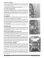
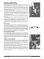
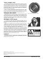
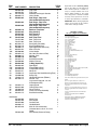
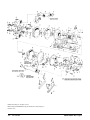
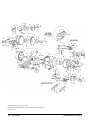
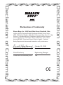
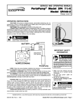
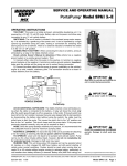
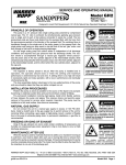
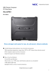
SERVICE AND OPERATING MANUAL
®
Models W09 and W15
Type 1
PLEASE NOTE!
The photos shown in this manual are for general instruction only. Your
specific model may not be shown. Always refer to the parts list and exploded
view drawing for your specific model when installing, disassembling or
servicing your pump.
PRINCIPLE OF PUMP OPERATION
This flap swing check valve pump is powered by compressed air and is a 1:1
pressure ratio design. It alternately pressurizes the inner side of one diaphragm
chamber, while simultaneously exhausting the other inner chamber. This
causes the diaphragms, which are connected by a common rod, to move
endwise. Air pressure is applied over the entire surface of the diaphragm, while
liquid is discharged from the opposite side. The diaphragm operates under a
balanced condition during the discharge stroke, which allows the unit to be
operated at discharge heads over 200 feet (61 meters) of water head.
Since the diaphragms are connected by a common rod, secured by plates
to the center of the diaphragms, one diaphragm performs the discharge stroke,
while the other is pulled to perform the suction stroke in the opposite chamber.
For maximum diaphragm life, keep the pump as close to the liquid being
pumped as possible. Positive suction head in excess of 10 feet of liquid (3.048
meters) may require a back pressure regulating device. This will maximize
diaphragm life.
Alternate pressuring and exhausting of the diaphragm chamber is performed
by means of an externally mounted, pilot operated, four-way spool type air
distribution valve. When the spool shifts to one end of the valve body, inlet air
pressure is applied to one diaphragm chamber and the other diaphragm
chamber exhausts. When the spool shifts to the opposite end of the valve body,
the porting of chambers is reversed. The air distribution valve spool is moved
by an internal pilot valve which alternately pressurizes one side of the air
distribution valve spool, while exhausting the other side. The pilot valve is
shifted at each end of the diaphragm stroke by the diaphragm plate coming in
contact with the end of the pilot valve spool. This pushes it into position for
shifting of the air distribution valve.
The chambers are manifolded together with a suction and discharge
flap-type check valve for each chamber, maintaining flow in one direction
through the pump.
INSTALLATION & START-UP
Locate the pump as close to the product being pumped as possible, keeping
suction line length and number of fittings to a minimum. Do not reduce line size.
For installations of rigid piping, short flexible sections of hose should be
installed between pump and piping. This reduces vibration and strain to the
piping system. A Warren Rupp Tranquilizer® surge suppressor is recommended
to further reduce pulsation in flow.
This pump was tested at the factory prior to shipment and is ready for
operation. It is completely self-priming from a dry start for suction lifts of 20 feet
(6.096 meters) or less. For suction lifts exceeding 20 feet of liquid, fill the
chambers with liquid prior to priming.
AIR SUPPLY
Air supply pressures cannot exceed 125 psi (8.61 bar). Connect the pump
air inlet to an air supply of sufficient capacity and pressure required for desired
performance. When the air line is solid piping, use a short length of flexible
hose (not less than ¾" (19mm) in diameter) between pump and piping to
eliminate strain to pipes.
IMPORTANT
Read these safety warnings
and instructions in this
manual completely, before
installation and start-up
of the pump. It is the
responsibility of the purchaser to retain this
manual for reference. Failure to comply with the
recommendations stated in this manual will
damage the pump, and void factory warranty.
WARNING
Take action to prevent
static sparking. Fire or
explosion
can
result,
especially when handling
flammable liquids. The pump,
piping,
valves,
containers
or
other
miscellaneous equipment must be grounded.
CAUTION
Before pump operation,
inspect all gasketed fasteners
for looseness caused by
gasket creep. Re-torque
loose fasteners to prevent leakage. Follow
recommended torques stated in this manual.
WARNING
Before doing any maintenance on the pump, be
certain all pressure is
completely vented from the
pump, suction, discharge,
piping, and all other openings and connections. Be
certain the air supply is locked out or made
non-operational, so that it cannot be started while
work is being done on the pump. Be certain that
approved eye protection and protective clothing are
worn all times in the vicinity of the pump. Failure to
follow these recommendations may result in serious
injury or death.
WARNING
In the event of diaphragm
rupture, pumped material may
enter the air end of the pump,
and be discharged into the
atmosphere. If pumping a
product which is hazardous or toxic, the air exhaust
must be piped to an appropriate area for safe
disposition.
WARNING
Before maintenance or repair,
shut off the com-pressed air
line, bleed the pressure, and
disconnect the air line
from the pump. The discharge
line may be pressurized
and must be bled of its pressure.
WARREN RUPP, INC. A Unit of IDEX Corporation • P.O. Box 1568 • Mansfield, Ohio 44901-1568 USA • (419) 524-8388 Fax (419) 522-7867 • www.warrenrupp.com
7/04
520-150-000
Models W09 & W15 Page 1
AIR INLET & PRIMING
For start-up, open an air valve approximately ½" to ¾" turn. After the unit primes,
an air valve can be opened to increase flow as desired. If opening the valve
increases cycling rate, but does not increase flow rate, cavitation has occurred, and
the valve should be closed slightly.
For the most efficient use of compressed air and the longest diaphragm life, throttle
the air inlet to the lowest cycling rate that does not reduce flow.
AIR VALVE LUBRICATION
The air end pilot and distribution valves of this pump are designed to operate
without lubrication. However, if poor quality compressed air is interfering with valve
shifting, lubrication may enhance operation. A small amount of non-detergent
lightweight oil (SAE 10 wt. maximum) added at the air inlet port, or the addition of a
Warren Rupp FRL unit (filter/regulator/lubricator) will help the pump operate. If the
air supply is contaminated, dirty, or excessively wet, an air dryer will remove most
water and impurities.
AIR EXHAUST
If a diaphragm fails, the pumped liquid or fumes can enter the air end of the pump,
and be exhausted into the atmosphere. When pumping hazardous or toxic materials,
pipe the exhaust to an appropriate area for safe disposition.
This pump can be submerged if materials of construction are compatible with the
liquid. The air exhaust must be piped above the liquid level. Piping used for the air
exhaust must not be smaller than 1" (2.54 cm). Reducing the pipe size will restrict air
flow and reduce pump performance. When the product source is at a higher level
than the pump (flooded suction), pipe the exhaust higher than the product source to
prevent siphoning spills.
Freezing or icing-up of the air exhaust can occur under certain temperature and
humidity conditions. Use of an air dryer should eliminate most icing problems.
Figure 1: Loosening locking knobs
BETWEEN USES
When used for materials that tend to settle out or transform to solid form, the pump
should be completely flushed after each use, to prevent damage. Product remaining
in the pump between uses could dry out or settle out. This could cause problems with
valves and diaphragms at re-start. In freezing temperatures, the pump must be
drained between uses in all cases.
CHECK VALVE INSPECTION & CLEAN-OUT
This pump has replaceable flap-type check valves on suction and discharge of
both outer chambers. A special wrench (See Figure 1.) is provided with each pump.
With it, all fasteners (locking knobs) securing the chambers and valves can be
removed. This allows quick and easy access to all four check valves. A standard ¾"
socket wrench can also be used to loosen locking knobs.
This wastewater pump is designed to handle small and large solids, up to nearly
inlet size; dry sludge; and stringy materials. Solids may occasionally become lodged
between the flap valve and seat. By loosening one locking knob holding the cover
plate yoke, the flap valve is accessible to dislodge debris. (See Figure 2.) This also
allows the insertion of a water hose to flush the outer chambers. Flush the pump by
opening all valve covers (note Caution on Page 1) and allowing water to flow in the
top and out the bottom port on each side of the pump.
Figure 2: Check valve clean out
CHECK VALVE REPLACEMENT
To replace the check valves, remove the four (4) 3/8" hex nuts. When removed,
the flange on the suction side carries the valve and seat as an assembly. On the
discharge side, the valve and seat will remain with the diaphragm housing. If parts
are being replaced, remove the self-locking nuts to gain access. The large rivet
head on the valve faces toward the seat. Replace the hinge pad and retainer if wear
is evident. Valves must sit flat against the seat. Adjust the fit by tightening the 3/8"
hex nuts.
Use caution when reassembling check valves. The flap valves are designed for
some preload over the retainer hinge pad. This is to insure proper face contact with
the seat. After all parts are in place, tighten the lock nuts on the assembly. Visual
inspection should show the seat and valve face fitting together without a gap. This
fit is important for dry priming. Once primed, the valves will function normally under
differential pressure.
7/04
520-150-000
Figure 3: Air distribution valve
Models W09 & W15 Page 2
EXTERNALLY SERVICEABLE
MAIN AIR DISTRIBUTION VALVE
The sleeve and spool set is located in the valve body, which is held onto the
intermediate bracket by four (4) capscrews. Loosening the four (4) hex head
capscrews allows the valve body to drop out of place (See Figure 3).
Once the valve body is off the pump, remove the four capscrews on the endcap to
inspect the spool and sleeve set. The spool of the air distribution valve is closely
sized to the sleeve. The spool must slide freely in the sleeve. Accumulation of dirt
and contaminants may prevent the spool from moving freely. It may stick in a position
that prevents the pump from cycling.
The plungers (visual stroke indicator) are locked in place on each end of the brass
spool. Before removal, mark the spool and the sleeve, so the spool can be
reassembled in the same end from which it was removed. A spring will be on one
side only, within the spool cavity. The plungers in the spool slide through a brass
bushing and o-ring in the cap.
Clean all parts before reassembly. Use a safety solvent and air oil to keep the
parts from oxidizing. Any nicks on the spool should be removed with a fine stone or
crocus cloth.
When removing the stainless steel sleeve, carefully press it out of the body,
preferably using an arbor press. Reinstall it into the body until it bottoms out against
the opposite endcap and bumper. Use new o-rings when reinstalling and apply a
light coating of grease or O-ring lube before placing in the valve body.
Reinstall the bumper(s), spring, and new gaskets. Tighten the four capscrews to
eliminate air leakage. Reinstall the body on the intermediate bracket with new
gaskets.
Figure 4: Locking pin
PILOT VALVE
The pilot valve assembly is accessed by removing the main air distribution valve
body from the pump and lifting the pilot valve body out of the intermediate housing.
Most problems with the pilot valve can be corrected by replacing the O-rings.
Always grease the spool prior to inserting it into the sleeve. If the sleeve is removed
from the body, reinsertion must be at the chamfered side. Grease the o-rings to slide
the sleeve into the valve body. Securely insert the retaining ring around the sleeve.
When reinserting the pilot valve, push both plungers (located inside the intermediate
bracket) out of the path of the pilot valve spool ends to avoid damage.
CAUTION
Locking pin must be removed before
operation.
PILOT VALVE ACTUATOR
Bushings for the pilot valve actuators are threaded into the intermediate bracket
from the outside. The plunger may be removed for inspection or replacement. First
remove the air distribution valve body and the pilot valve body from the pump. The
plungers can be located by looking into the intermediate. It may be necessary to use
a fine piece of wire to pull them out. The bushing can be turned out through the inner
chamber by removing the outer chamber assembly. Replace the bushings if pins
have bent.
MANUAL VALVE OVERRIDE
As the pump shifts, the rods from the main air valve move through the endcap. A
rod on the manual override (see Figure 4) can be locked to one side. A pin is provided
to do so. If the rod is on the left, the left side of the pump is on a discharge stroke.
When the pump is cycling, keep fingers away from the override rod and pump
casting. A shield is installed in this area for protection.
By locking the air valve to one side, air cannot flow through the pump, and the
pump will not shift. Use extreme caution when opening clean-out ports. Vent both air
and fluid pressure in the pump and system, prior to opening.
The manual override can also be used to move air through the pump, at low
pressures, to clear blockages. Typically, about 15 psi (1 bar) of air is all that can be
applied to the pump by manually moving the override rods. The valve override can
also be helpful when checking through the troubleshooting points mentioned
elsewhere in this manual.
7/04
520-150-000
Figure 5: Chamber vent
Models W09 & W15 Page 3
TAPPED CHAMBER VENTS
The chamber vent at the top of each outer chamber (see Figure 5) is used to
purge any entrapped air that might accumulate in the chamber. Entrapped air
could cause unbalanced cycling or loss of prime. The gate valve with 1/2" NPT
(12.7mm) threads accomodates a hose or pipe, to vent accumulated air and
fluid back to the liquid source. Ends of the hose or pipe must be submerged in
the liquid being pumped. Tying the pump sides together into a common hose
only moves the air from side to side.
When air is purged, pumped product will discharge from the hose. When
this occurs, close the gate valve and continue normal operation. The valves
may be left partially open, but pump performance will decrease. The tapped
chamber vents can also be used to flush the chambers between uses.
DIAPHRAGM REPLACEMENT
Diaphragms are in-line accessible for service, without disturbing the suction
and discharge flanges. To access the diaphragm, remove the eight (8) locking
knobs around the diaphragm chamber. Remove the locking knobs at the
manifold elbow connections. The housing assembly will pull off. Diaphragms
can now be inspected or replaced. Clear all foreign matter from behind the
diaphragm before reassembling.
Figure 6: Align hexhead capscrews and tighten
REASSEMBLY AFTER SERVICE
To reassemble the pump, begin with the diaphragm assembly. Stack the
wear pad onto the stud of the outer plate. Next, put the diaphragm on to the
stud, with the natural bulge toward the outer plate. Place the inner plate onto
the stud.
Align the five (5) hexhead capscrews and washers through the inner plate,
diaphragm and wear pad, into the outer plate (See Figure 6). Tighten the
capscrews alternately, side to side and corner to corner, use 242 Loctite and
torque to 190 in/lbs. Place the bumper onto the diaphragm rod.
Once the diaphragm assembly is made, thread the stud (from the outer
plate side) into the diaphragm rod. Use Neverseize® or equivalent anti-galling
thread lubricant on threads. Turn the assembly onto the rod until it bottoms out,
and the eight (8) holes around the outside of the diaphragm line up with those
on the outer chamber rim (See Figure 7). Back-off tightening as required for
alignment. Reassemble the other side of the pump in the same way. Tighten all
locking knobs to secure the outer chamber to the inner chamber. Tighten all
knobs alternately, side to side and corner to corner.
WARRANTY
This pump is warranted for a period of five years against defective material
and workmanship. Failure to comply with the recommendations stated in this
manual voids all factory warranty.
Figure 7: Align diaphragm holes with chamber
holes
WARNING
This pump is pressurized
internally with air pressure
during operation. Always
make certain that all bolting
is in good condition and that
all of the correct bolting is
reinstalled during assembly.
©2004 Warren Rupp, Inc. All rights reserved.
®Warren Rupp, SANDPIPER and Tranquilizer are registered tradenames of Warren Rupp, Inc.
®Neverseize is a registered tradename of Loctite
Printed in U.S.A.
7/04
520-150-000
Models W09 & W15 Page 4
SERVICE AND OPERATING MANUAL
®
Model W09
Type 1
ITEM
NO.
1
2
3
4
5
6
6-A
6-B
6-C
6-D
6-E
6-F
7
8
9
10
11
12
13
14
15
16
17
18
19
20
21
22
23
24
25
27
28
29
30
31
32
33
34
35
36
37
PART NUMBER
070-006-170
114-018-010
720-004-360
135-016-162
620-011-114
095-073-000
095-070-551
755-025-000
560-033-360
775-026-000
560-023-360
675-037-080
360-041-379
560-001-360
095-076-010
132-014-358
165-066-010W
360-048-425
360-010-425
560-020-360
031-066-000
170-032-115
170-045-115
115-121-080
132-025-000
196-132-010
196-131-010
286-060-365
286-060-360
286-060-354
560-022-360
612-138-010
685-007-120
170-024-115
807-080-330
115-122-080
170-053-115
115-124-080
807-079-115
900-001-115
612-136-010
312-089-010
312-091-010
338-010-357
338-005-365
TOTAL
DESCRIPTION
RQD.
Bearing, Sleeve
2
Bracket, Intermediate
1
Seal, U-Cup
2
Bushing, Threaded
2
Plunger, Actuator
2
Pilot Valve Body Assembly1
1
Pilot Valve Body
1
Sleeve (With O-Ring)
1
O-Ring (Sleeve)
4
Spool (With O-Ring)
1
O-Ring (Spool)
2
Retaining Ring
1
Gasket, Valve Body
1
O-Ring (Actuator Plunger)
2
Body, Valve
1
Bumper, Valve Spool
2
Cap, End (Includes Item 55)
2
Gasket, Valve Body2
1
Gasket, End Cap
2
O-Ring (Sleeve O.D.)
6
Sleeve & Spool Set
1
Capscrew, Hex Head
8
Capscrew, Hex Head
4
Mounting Foot, Left Hand
2
Bumper, Diaphragm
2
Chamber, Inner
2
Chamber, Outer
2
Diaphragm
2
Diaphragm
2
Diaphragm
2
O-Ring (Intermediate)
2
Plate, Diaphragm (Outer)
2
Rod, Diaphragm
1
Capscrew, Hex Head (Intermediate)
8
Stud (Outer Plate)
2
Mounting Foot, Right Hand
2
Hex Head Capscrew (Diaphr. Plate) 10
Mounting Foot
2
Stud, Inner (Chamber)
4
Washer, Lock (Inner/Outer Plate)
10
Plate, Diaphragm (Inner)
2
Elbow, Suction
2
Elbow, Discharge
2
Flap Valve
4
Flap Valve
4
1Pilot Valve Body Assembly available in kit form. Order 031-064-000
Repair Parts shown in bold face (darker)
type are more likely to need replacement
after extended periods of normal use.
They are readily available from most
Warren Rupp distributors. The pump
owner may prefer to maintain a limited
inventory of these parts in his own stock
to reduce repair downtime to a minimum.
IMPORTANT: When ordering repair parts
always furnish pump model number,
serial number and type number.
MATERIAL CODES
The Last 3 Digits of Part Number
000…Assembly, sub-assembly;
and some purchased Items
010…Cast Iron
012…Powered Metal
015…Ductile Iron
020…Ferritic Malleable Iron
025…Music Wire
080…CarbonSteel AISI B-1112
100…Alloy 20
110…Alloy Type 316 Stainless Steel
111…Alloy Type 316 Stainless Steel (Electro Polished)
112…Alloy “C”
113…Alloy Type 316 Stainless Steel (Hand Polished)
114…303 Stainless Steel
115…302/304 Stainless Steel
117…440-C Stainless Steel (Martensitic)
120…416 Stainless Steel (Wrought Martensitic)
123…410 Stainless Steel (Wrought Martensitic)
148…Hardcoat Anodized Aluminum
149…2024-T4 Aluminum
150…6061-T6 Aluminum
151…6063-T6 Aluminum
152…2024-T4 Aluminum (2023-T351)
154…Almag 35 Aluminum
155 or 156…356-T6 Aluminum
157…Die Cast Aluminum Alloy #380
158…Aluminum Alloy SR-319
159…Anodized Aluminum
162…Brass, Yellow, Screw Machine Stock
165…Cast Bronze, 85-5-5-5
166…Bronze SAE 660
170…Bronze, Bearing Type, Oil Impregnated
180…Copper Alloy
310…Kynar® Coated
330…Zinc Plated Steel
331…Chrome Plated Steel
332…Electroless Nickel Plated
335…Galvanized Steel
336…Zinc Plated Yellow Brass
337…Silver Plated Steel
340…Nickel Plated
342…Filled Nylon
354…Injection Molded #203-40 Santoprene- Duro 40D ± 5;
Color: RED
355…Thermoplastic Elastomer
356…Hytrel
357…Rupplon (Urethane Rubber) Color coded:PURPLE
358…Rupplon(UrethaneRubber)Color coded:PURPLE
(Some Applications, Compression Mold)
359…Urethane Rubber
360…Buna-N Rubber Color coded: RED
361…Buna-N
363…Viton (Fluorel) Color coded: YELLOW
364…E.P.D.M. Rubber Color coded: BLUE
365…Neoprene Rubber Color coded: GREEN
370…Butyl Rubber Color coded: BROWN
371…Philthane (Tuftane)
List continued next page
which includes items 5,7,8 & 12.
2Use gasket adhesive during assembly.
7/04
520-150-000
Models W09 & W15 Page 5
ITEM
NO.
40
41
42
PART NUMBER
DESCRIPTION
338-005-360
338-010-354
518-113-010
980-004-115
570-001-365
Flap Valve
Flap Valve
Manifold, Discharge & Suction
Yoke, Handle
Pad, Hinge - Flap Valve
(Not used with Santoprene)
Pad, Hinge - Flap Valve
(Not used with Santoprene)
Pad, Hinge - Flap Valve
(Not used with Santoprene)
Retainer, Flap Valve
Ring, Sealing
Ring, Sealing
Ring, Sealing
Seat, Flap Valve
Seat, Flap Valve
Seat, Flap Valve
Stud, Outer (Chamber)
Stud (Flap Retaining)
Pipe Nipple (Shut-Off Valve)
Shut-Off Valve
Valve Handle
Nut, Hex (Chamber at Feet)
Washer, Lock
Nut, Stop
Stud Nut Assembly
Muffler, Exhaust
O-Ring (Spool Pin)
Pipe Nipple
Flange (W09-2 Only)
Flange (W09-3 Only)
Wear pad
Capscrew, Hex Head (Mounting Feet)
Safety Clip
Hex Head Capscrew (Elbows)
Washer, Flat
(in place of hinge pad - for use
w/Santoprene only)
Locking Knob
O-Ring (Clean-Out)
Clean-Out Cap
Clean-Out Clamp Assembly
Stud Nut Assembly
570-001-364
570-001-360
43
44
45
46
47
48
49
49A
50
51
52
53
54
55
56
57A
57B
58
59
60
61
62
64
65
66
67
68
670-044-110
675-013-365
675-013-364
675-013-360
722-071-360
722-071-363
722-071-364
807-016-115
807-018-110
538-080-115
893-013-162
405-008-000
545-007-115
900-006-115
547-002-110
542-015-115
530-008-000
560-023-360
538-082-335
334-095-010
334-094-010
570-014-371
170-058-115
210-008-330
170-031-115
901-035-115
478-007-115
560-012-360
165-063-010
200-054-015
542-014-115
TOTAL
RQD.
4
4
2
4
4
4
4
4
4
4
4
4
4
4
20
8
2
2
2
8
20
8
4
1
2
2
2
2
2
4
1
8
4
Repair Parts shown in bold face (darker)
type are more likely to need replacement
after extended periods of normal use.
They are readily available from most
Warren Rupp distributors. The pump
owner may prefer to maintain a limited
inventory of these parts in his own stock
to reduce repair downtime to a minimum.
IMPORTANT: When ordering repair parts
always furnish pump model number,
serial number and type number.
MATERIAL CODES
The Last 3 Digits of Part Number
Continued from previous page
375…Fluorinated Nitrile
378…High density Polypropylene
379…Conductive Nitrile
405…Cellulose Fibre
408…Cork and Neoprene
425…Compressed Fibre
426…Blue Gard
440…Vegetable Fibre
465…Fibre
500…Delrin 500
501…Delrin 570
505…Acrylic Resin Plastic
520…Injection Molded PVDF Natural Color
540…Nylon
541…Nylon
542…Nylon
544…Nylon Injection Molded
550…Polyethylene
551…Polypropylene
552…Unfilled Polypropylene
553…Unfilled Polypropylene
555…Polyvinyl Chloride
570…Rulon II
580…Ryton
590…Valox
591…Nylatron G-S
592…Nylatron NSB
600…PTFE (virgin material) Tetrafluoroethylene (TFE)
601…PTFE (Bronze and moly filled)
602…Filled PTFE
603…Blue Gylon
604…PTFE
606…PTFE
610…PTFE Encapsulated Silicon
611…PTFE Encapsulated Viton
Delrin, Viton and Hytrel are registered tradenames of E.I.
DuPont.
Gylon is a registered tradename of Garlock. Inc.
Nylatron is a registered tradename of Polymer Corp.
24
4
4
4
8
Rulon II is a registered tradename of Dixion Industries
Corporation.
Hastelloy-C is a registered tradename of Cabot Corp.
Ryton is a registered tradename of Phillips Chemical
Company.
Valox is a registered tradename of General Electric
Company.
Kynar® is a registered tradename of ATOFINA
Chemicals, Inc.
Not Shown:
535-069-000
705-001-330
535-037-000
930-009-115
031-067-010
705-001-330
7/04
520-150-000
Name Plate
Drive Screw
Caution Plate
Handle Wrench
Main Air Valve Assembly
(Includes Items 9,10,11,13,14,15,
16,60)
Drive Screw (Cleanout Clamp)
1
2
4
1
1
Warren Rupp, Rupplon, SANDPIPER, PortaPump,
Tranquilizer, and SludgeMaster are registered
tradenames of Warren Rupp Inc.
2
Models W09 & W15 Page 6
©2004 Warren Rupp, Inc. All rights reserved.
®Warren Rupp and SANDPIPER are registered tradenames of Warren Rupp, Inc.
Printed in U.S.A.
7/04
520-150-000
Models W09 & W15 Page 7
SERVICE AND OPERATING MANUAL
Model W15
®
Type 1
ITEM
NO.
1
2
3
4
5
7
8
9
10
10-A
10-B
10-C
10-D
10-E
10-F
11
12
13
14
15
16
17
18
19
20
21
22
23
24
25
26
27
28
29
30
31
32
33
34
36
37
38
PART NUMBER
DESCRIPTION
070-006-170
114-018-010
560-023-360
135-016-162
620-011-114
360-041-379
560-001-360
132-014-358
095-073-000
095-070-551
755-025-000
560-033-360
775-026-000
560-023-360
675-037-080
165-066-010W
360-048-425
360-010-425
560-020-360
031-069-000
170-032-115
095-076-010
196-129-015
560-022-360
170-045-115
530-008-000
685-041-120
115-123-080
170-024-115
900-006-115
720-004-360
722-067-010
115-124-080
132-026-000
612-135-010
560-051-360
612-133-010
286-059-365
286-059-360
286-059-354
900-003-115
570-013-371
165-062-010
200-055-015
Bearing, Sleeve
Bracket, Intermediate
O-Ring (Spool Pin)
Bushing, Threaded
Plunger, Actuator
Gasket, Valve Body
O-Ring
Bumper, Valve Spool
Assembly, Pilot Valve1
Valve Body
Sleeve (without O-Ring)
O-Ring (Sleeve)
Spool (without O-Ring)
O-Ring (Spool)
Retaining Ring
Cap, End
Gasket, Valve Body2
Gasket, End Cap
O-Ring
Sleeve & Spool Set
Capscrew, Hex Head
Body, Valve
Chamber, Inner
O-Ring
Capscrew, Hex Head
Muffler, Exhaust
Rod, Diaphragm
Bracket, Support
Capscrew, Hex Head
Washer, Lock
Seal, U-Cup
Seat, Flap Valve-Angle
Mounting Foot
Bumper, Diaphragm Plate
Plate, Outer Diaphragm Assembly
O-Ring (Clean-Out Cap)
Plate, Inner Diaphragm
Diaphragm
Diaphragm
Diaphragm
Washer, Lock
Wear Pad
Clean-Out Cap
Clean-Out Clamp Assembly
TOTAL
RQD.
2
1
2
2
2
1
2
2
1
1
1
4
1
2
1
2
1
2
6
1
8
1
2
2
4
1
1
4
8
8
2
4
2
2
2
4
2
2
2
2
20
2
4
4
Repair Parts shown in bold face (darker)
type are more likely to need replacement
after extended periods of normal use.
They are readily available from most
Warren Rupp distributors. The pump
owner may prefer to maintain a limited
inventory of these parts in his own stock
to reduce repair downtime to a minimum.
IMPORTANT: When ordering repair parts
always furnish pump model number,
serial number and type number.
MATERIAL CODES
The Last 3 Digits of Part Number
000…Assembly sub assembly;
and some purchased items
010…Cast Iron
015…Ductile Iron
080…Carbon Steel AISI B-1112
100…Alloy 20
110…Alloy Type 316 Stainless Steel
112…Alloy “C”
114…303 Stainless Steel
115…301/302/304 Stainless Steel
120…416 Stainless Steel (Wrought Martensitic)
148…Hardcoat Anodized Aluminum
150…6061-T6 Aluminum
151…6063-T6 Aluminum
154…Almag 35 Aluminum
155 or 156…356-T6 Aluminum
157…Die Cast Aluminum Alloy #380
159…Anodized Aluminum
162…Brass Yellow Screw Machine Stock
170…Bronze Bearing Type Oil Impregnated
180…Copper Alloy
330…Plated Steel
331…Chrome Plated Steel
332…Electroless Nickel Plated
335…Galvanized Steel
356…Hytrel
357…Rupplon (Urethane Rubber)
360…Buna-N Rubber Color coded: RED
363…Viton (Fluorel) Color coded: YELLOW
364…E.P.D.M Rubber Color coded: BLUE
365…Neoprene Rubber Color coded: GREEN
366…Food Grade Nitrile Color coded: WHITE
375…Fluorinated Nitrile
379…Conductive Nitrile
405…Cellulose Fibre
408…Cork and Neoprene
425…Compressed Fibre
440…Vegetable Fibre
500…Delrin 500
501…Delrin 570
520…Injection Molded PVDF Natural Color
541…Nylon, glass filled
542…Nylon, unfilled
550…Polypropylene
551…Polypropylene, glass filled
552…Polypropylene, unfilled
555…PVC (Polyvinyl Chloride)
580…Ryton
600…PTFE (virgin material) Tetrafluoroethylene (TFE)
603…Blue Gylon
604…PTFE – Diaphragm
606…PTFE
610…PTFE Encapsulated Silicon
611…PTFE Encapsulated Viton
continued next page
1Pilot Valve Body Assembly available in kit form. Order 031-064-000
which includes items 5,7,8 & 12.
2Use gasket adhesive during assembly.
7/04
520-150-000
Models W09 & W15 Page 8
ITEM
NO.
39
40
41
42
43
44
PART NUMBER
807-042-115
210-008-330
900-005-115
170-012-115
360-079-425
360-080-425
DESCRIPTION
Stud
Safety Clip
Washer, Lock
Capscrew, Hex Head
Gasket, Seat
Gasket, Flange (quautity of 8 with
TOTAL
RQD.
16
1
10
12
4
4
Santoprene- see item 62 below)
45
46
47
48
49
50
51
52
53
54
55
56
57
58
59
60
61
62
63
64
65
66
67
73
670-043-110
Retainer, Flap Valve
807-044-115
Stud
170-018-115
Capscrew, Hex Head
545-008-110
Nut, Hex
807-018-110
Stud
547-002-110
Nut, Stop
334-020-000
Flange, Follower
360-021-000
Gasket
170-055-115
Capscrew, Hex Head
901-006-115
Flat Washer
807-078-330
Stud
196-128-010
Chamber, Outer
312-087-010
Elbow, Suction
312-086-010
Elbow, Discharge
518-112-010
Manifold
478-005-115
Locking Knob
338-011-357
Flap Valve
338-011-354
Flap Valve
338-008-360
Flap Valve
338-008-365
Flap Valve
570-002-360
Pad, Hinge
570-002-365
Pad, Hinge
901-035-115
Washer, Flat
(in place of hinge pad - for use with Santoprene only)
542-013-115
Stud Nut Assembly
980-004-115
Handle Yoke
807-077-115
Stud (Mounting Brkt.)
893-013-162
Shut-Off Valve
538-081-115
Pipe Nipple
807-081-118
Stud
W15-4 Unit Only
68
334-097-010
69
807-005-115
70
900-007-115
71
545-009-110
72
360-036-426
Not Shown:
535-037-000
930-009-115
031-070-010
4
8
10
8
8
8
4
4
8
40
2
2
2
2
2
44
4
4
4
4
4
4
8
Repair Parts shown in bold face (darker)
type are more likely to need replacement
after extended periods of normal use.
They are readily available from most
Warren Rupp distributors. The pump
owner may prefer to maintain a limited
inventory of these parts in his own stock
to reduce repair downtime to a minimum.
IMPORTANT: When ordering repair parts
always furnish pump model number,
serial number and type number.
Delrin, Viton and Hytrel are registered tradenames of E.I.
DuPont.
Gylon is a registered tradename of Garlock. Inc.
Nylatron is a registered tradename of Polymer Corp.
Rulon II is a registered tradename of Dixion Industries
Corporation.
Hastelloy-C is a registered tradename of Cabot Corp.
Ryton is a registered tradename of Phillips Chemical
Company.
Valox is a registered tradename of General Electric
Company.
Kynar® is a registered tradename of ATOFINA
Chemicals, Inc.
Warren Rupp, Rupplon, SANDPIPER, PortaPump,
Tranquilizer, and SludgeMaster are registered
tradenames of Warren Rupp Inc.
8
4
8
2
2
12
Flange, Adapter
Stud
Washer, Lock
Nut, Hex
Gasket, Flange
2
8
8
8
2
Caution Plate
Handle Wrench
Main Air Valve Assembly
(Includes items 9,13,14,15,16,17,40)
2
1
1
1Order item 10 in kit form only. Order 031-064-000 which also includes
items 5,7,8 & 12.
7/04
520-150-000
Models W09 & W15 Page 9
©2004 Warren Rupp, Inc. All rights reserved.
®Warren Rupp and SANDPIPER are registered tradenames of Warren Rupp, Inc.
Printed in U.S.A.
7/04
520-150-000
Models W09 & W15 Page 10
Declaration of Conformity
Warren Rupp, Inc., 800 North Main Street, Mansfield, Ohio,
certifies that Air-Operated Double Diaphragm Metallic Pumps Series:
HDB, HDF, S Non-Metallic, S Metallic, Containment Duty, Gas, UL, High
Pressure, W, Submersible and Tranquilizers comply with the European
Community Directive 98/37/EC, Safety of Machinery. This product
has used EN 809, Pumps and Pump Units for Liquids - Common
Safety Requirements harmonized standard to verify conformance.
October 20, 2005
Signature of authorized person
Date of issue
David Roseberry
Engineering Manager
Printed name of authorized person
Title
CE