1
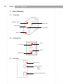
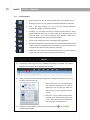
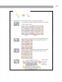
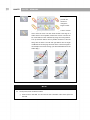
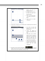
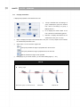
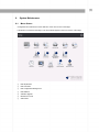
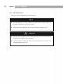
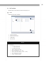
1 User Manual Driller HDM-8000 2 HUVITZ KAIZER HDM-8000 IMPORTANT NOTICE This product may malfunction due to electromagnetic waves caused by portable personal telephone, transceivers, radio-controlled toys, etc. Be sure to avoid having the above objects, which affect the normal operation of the product, brought near the product. The information in this publication has been carefully checked and is believed to be entirely accurate at the time of publication. HUVITZ assumes no responsibility, however, for possible errors or omissions, or for any consequences resulting from the use of the information contained herein. HUVITZ reserves the right to make changes in its products or product specifications at any time and without prior notice, and is not required to update this documentation to reflect such changes. 9000ENGS001-A Ver 1.0 (Jun. 2013) ©2013 HUVITZ Co., Ltd. 298-29 Gongdan-ro, Gunpo-si, Gyeongi-do 435-862, Republic of Korea All rights reserved. Under copyright laws, this manual may not be copied, in whole or in part, without the prior written consent of HUVITZ Co., Ltd. 3 CONTENTS 1. Introduction ....................................................................................................................................... 5 1.1. 1.2. 1.3. 2. Safety Information .............................................................................................................................. 6 2.1. 2.2. 2.3. 2.4. 3. Main Features .......................................................................................................................... 5 System Configuration................................................................................................................ 5 Classification ........................................................................................................................... 5 Introduction ............................................................................................................................. 6 Safety Symbols ........................................................................................................................ 7 Environmental Considerations .................................................................................................... 8 Safety Precautions .................................................................................................................. 10 Driller (HDM-8000) .......................................................................................................................... 14 3.1. 3.2. 3.3. Front View ............................................................................................................................. 14 Drilling Room ........................................................................................................................ 14 Rear View.............................................................................................................................. 14 4. Installation Procedure ....................................................................................................................... 15 5. Operation ......................................................................................................................................... 16 5.1. 5.2. Control Panel ......................................................................................................................... 16 Operating Procedure ............................................................................................................... 17 5.2.1. Drilling Process ...........................................................................................................................................17 5.2.2. Drilling Assignment ....................................................................................................................................18 5.2.3. Start Drilling ................................................................................................................................................19 5.2.4. Drilling Completion....................................................................................................................................20 5.2.5. Drill Retouch Mode ....................................................................................................................................22 5.3. Hole Editor ............................................................................................................................ 23 6. 5.3.1. Upper Side of Hole Editor .........................................................................................................................24 5.3.2. Working Area ...............................................................................................................................................24 5.3.3. Preview .........................................................................................................................................................25 5.3.4. Function Buttons .........................................................................................................................................26 5.3.5. List of Hole/Slot ..........................................................................................................................................32 5.3.6. Property of Hole/Slot..................................................................................................................................34 System Maintenance ......................................................................................................................... 35 6.1. 6.2. 6.3. Menu Screen .......................................................................................................................... 35 Drill Adjustments ................................................................................................................... 36 Drill Test Mode ...................................................................................................................... 37 6.3.1. Sensor ............................................................................................................................................................37 6.3.2. Z / Y / R / Tilting .........................................................................................................................................38 6.3.3. Motor / Clamp .............................................................................................................................................39 6.4. Drill Configuration Management .............................................................................................. 40 6.5. Drill Statistics ........................................................................................................................ 41 6.5.1. 6.6. 6.7. 6.8. Current Statistics .........................................................................................................................................41 6.5.2. Total Statistics..............................................................................................................................................42 Software Upgrade ................................................................................................................... 43 Maintenance Code .................................................................................................................. 44 Software Version .................................................................................................................... 44 4 HUVITZ 6.9. 7. HDM-8000 Maintenance Tips ................................................................................................................... 45 6.9.1. Drill Bit Replacement.................................................................................................................................45 6.9.2. Regular Maintenance..................................................................................................................................45 6.9.3. Fuse Replacement .......................................................................................................................................45 6.9.4. Cleaning ........................................................................................................................................................46 Specifications and Accessories ........................................................................................................... 47 7.1. 7.2. 7.3. 8. KAIZER Standard Accessories............................................................................................................... 47 Specifications......................................................................................................................... 47 Drawings of System ................................................................................................................ 48 SERVICE INFORMATION .............................................................................................................. 49 5 Introduction 1. This product is the drilling only machine used with the edger (HPE-8000). This device process the drilling data transmitted from the edger. 1.1. Main Features It can process different types of holes for various lens material. Material Plastic Glass Hi-Index Polycarbonate Trivex® Hole O X O O O Slot O X O O O Notch O X O O O Type With 3D technology it guarantees precise position, angle and size. Test Mode enables the operator to effectively perform the routine maintenance without technical assistance. 1.2. System Configuration Driller (HDM-8000) 1.3. Edger (HPE-8000) Classification This device complies with Part 15 of the FCC Rules. Operation is subject to the following two conditions: (1) this device may not cause harmful interference, and (2) this device must accept any interference received, including interference that may cause undesired operation. Class A equipment Class A equipment is intended for use in an industrial environment. In the documentation for the user, a statement shall be included drawing attention to the fact that there may be 6 HUVITZ KAIZER HDM-8000 potential difficulties in ensuring electromagnetic compatibility in other environments, due to conducted as well as radiated disturbances. Protection against electric shock: Class I(when earthed) Measurement Category: CAT II Pollution Degree: 2 Safety Information 2. 2.1. Introduction Safety is everyone’s responsibility. The safe use of this machine is largely dependent upon the installers, users, operators, and managers. It is prerequisite to read and understand these specifications before installing, using, cleaning, fixing or revising. Fully understanding the whole instructions must be the first priority. For this reason, the following safety notices have been placed appropriately within the text of this manual to highlight safety related information or information requiring special emphasis. All users, operators, and maintainers must be familiar with and pay particular attention to all signs of Warnings and Cautions. ! WARNING “Warning” indicates the presence of a hazard that could result in severe personal injury, death or substantial property damage if ignored. ! CAUTION “Caution” indicates the presence of a hazard that could result in minor injury, or property damaged if ignored.- NOTE This is used to emphasize essential information. Be sure to read this information to avoid operating the device incorrectly. 7 2.2. Safety Symbols The International Electrotechnical Commission (IEC) has established a set of symbols, which are listed below. This applies only to the instrument that has the certification symbol printed explicitly on the product label or sticker. I and O on power switch represent ON and OFF respectively. This symbol identifies caution, risk of danger. Ensure you understand the function of this control before using it. Control function is described in the appropriate User’s or Service Manual. Protective Earth Connection Disposal of your old appliance 1. When this crossed-out wheeled bin symbol is attached to a product it means the product is covered by the European Directive 2002/96/EC. 2. All electrical and electronic products should be disposed of separately from the municipal waste stream via designated collection facilities appointed by the government or the local authorities. 3. The correct disposal of your old appliance will help prevent potential negative consequences for the environment and human health. 4. For more detailed information about disposal of your old appliance, please contact your city office, waste disposal service or the shop where you purchased the product. Alternating Current 8 HUVITZ 2.3. KAIZER HDM-8000 Environmental Considerations Avoid the following environments for operation or storage: Where the machine is exposed to water vapor. Don’t operate the machine with wet hands Indoor use only Where the machine is exposed to direct sunlight. Where there are big changes in temperature. Optimal temperature range for normal operation is from 10C to 40C. (Humidity : 30 ~ 80%) Where there is a hot equipment nearby Where the humidity is extremely high or there is a ventilation problem. Where the machine is exposed to excessive shocks or vibrations. Where the machine is exposed to chemical material or explosive gas. Be cautious so that things like dust and metal do not fall inside the machine. 9 Don’t disassemble or open the product. HUVITZ does not take responsibility for the possible problems Be careful not to block the fan located on the backside of the machine. Don’t plug the AC power cord into the outlet unless all parts of the machine are completely connected. Otherwise, it will cause severe damage on the machine. Pull out the power cord with holding the plug, not the cord. To avoid risk of electric shock, this equipment must only be connected to a supply mains with protective earth. This instrument must be followed by these following conditions: 1. Operation An ambient temperature range of 10℃ ~ 40℃ (50°F ~ 104°F) A relative humidity range of 30% ~ 80% An atmospheric pressure range of 800 ~ 1060hpa 2. Transportation An ambient temperature range of -25℃ ~ 70℃ (-13°F ~ 158°F) A relative humidity range of 10% ~ 95% (with non-condensing) An atmospheric pressure range of 500 ~ 1060hpa 3. Storage An ambient temperature range of -25℃ ~ 70℃ (-13°F ~ 158°F) A relative humidity range of 10% ~ 95% (with non-condensing) An atmospheric pressure range of 700 ~ 1060hpa Please avoid where the equipment is exposed to excessive shocks or vibration. Operation time : Max 6 minutes for short-term operation Rest time : Min 2 minutes 10 HUVITZ KAIZER HDM-8000 Safety Precautions 2.4. This machine has been developed and tested according to safety standards as well as national and international standards. This guarantees a very high degree of safety for this device. HUVITZ is legally required to inform the users of all the information regarding safety. Observance of the instructions is the requirement for the safety. Therefore, please read carefully all instructions before switching on this machine. For more detailed information, please contact our Customer Service Department or one of our local agencies 1. This equipment must not be used (a) in an area that is in danger of explosions and (b) in the presence of flammable, explosive, or volatile solvent such as alcohol, benzene or similar chemicals. 2. Do not place or store this machine in humid area. Humidity should be maintained between 30 and 80% for normal operation. Do not expose the device to water splashes, dripping water, or sprayed water. Do not place containers with fluids, liquids, or gases on top of this machine 3. The machine must be operated by a trained and qualified person or under his or her supervision 4. Repair of this machine must be conducted by HUVITZ’s service technicians or other authorized persons. 5. Maintenance by users must observe the User’s Manual and Service Manual. Any additional maintenance may only be performed by HUVITZ’s service technicians or other authorized persons. 6. Manufacturers are responsible for the safety, reliability, and performance of this machine only when the following requirements are fulfilled: (1) When the machine has been installed in a proper area, following the manual. (2) When the machine has been operated and maintained according to the manual and service manual. 7. Manufacturers are not responsible for the damages caused by unauthorized alterations. Such tampering will forfeit any rights to receive services during the term of guarantee. 8. This machine must be connected with the accessories supplied by HUVITZ. If you are to use other accessories, their safety or usability must be checked and proved by their manufacturers or HUVITZ. 9. Only those who have undergone proper training and instructions are authorized to install, use, operate, and maintain this machine. 11 10. Keep the User’s Manual and Service Manual in a place easily accessible at all times for persons operating and maintaining the equipment. 11. Do not apply excessive force to cable connections. If the cable does not connect easily, make sure that the connector (plug) is appropriate for the receptacle (socket). If you caused any damage to a cable connector(s) or receptacle(s), let the damage(s) be repaired by an authorized service technician. 12. Please do not pull on any cable. Always grab the plug when disconnecting cables. 13. Before you use, check the exterior of the machine and its conditions 14. Do not block any ventilation outlet necessary for proper heat dissipation. 15. If smoke, sparks or any abnormal noise or smell is noticed coming from the machine, please switch the power off immediately and pull out the plug. 16. You may use your earplug as the machine makes noise while operating. 17. When you carry this product, at least two people are required to lift the equipment. 18. To avoid the risk of electric shock, this machine must only be connected to protective earth. 19. Do not place the machine where it is difficult to operate the disconnecting device (disconnecting device: power cord, appliance inlet, etc.) 20. The machine may be impaired if it is used in a manner not specified by the manufacturers or manual. ! WARNING Drilling room cover should be completely closed during the lens drilling process. If the lens is broken during the process, the broken pieces of lens may cause damage to the person. The debris may also cause damage to the human eyes If you find any crack on the base of the product, immediately stop the operation and ask for the service. If the product is broken during the operation, the broken pieces may cause a serious injury. Be sure not to drill the materials other than the spectacle lenses. Otherwise, it may weaken the drill bit performance and cause a crack on it. If the drill bit is broken, the broken pieces may cause a serious injury. Be sure not to operate the product unless the cover of the body is completely closed. 12 HUVITZ KAIZER HDM-8000 Otherwise, it may cause a serious injury. The machine should be properly installed and operated based on the instructions on this manual. If the power is turned on without unlocking the locking device for the carriage and feeler, it may cause damage to the product and cause malfunction of the product. Do not disassemble the product without receiving regular training. It may cause electric shock or serious injury during the operation or cause the malfunction of the product. Make sure that the material of the actual lens is identical with the selected lens material at the edger before starting the process. Otherwise, it may cause damage on the drill bit and shorten the lifetime of drill bit. The product should be properly installed and maintained at flat and even ground. Otherwise, it may affect the normal operation of the machine. Be sure that your fingers are not caught during clamping. When detaching the lens adapter from the process-finished lens, use the Adapter Remover supplied as the standard accessory. Do not pull out the lens adapter with your hands. ! CAUTION When moving the machine, first fix the stage and check whether the power supply is off. Then, two or more persons should lift the bottom of the product with both hands. When setting down the machine, make sure not to be interfered with the obstacles. Set down the product slowly in order to prevent any injury of human body or damage to the product. When moving the machine, make sure the locking device and the screw for the cover are properly tightened. When wrapping the machine, use recommended packaging and shock-absorbing materials in order to prevent damage during the transportation. Be sure to use the standard accessories or tools provided together with the product for the maintenance. Otherwise, it may cause the malfunction of the product. 13 NOTE This equipment has been tested and found to comply with the limits for a Class A digital device, pursuant to Part 15 of the FCC Rules. These limits are designed to provide reasonable protection against harmful interference when the equipment is operated in a commercial environment. This equipment generates, uses, and can radiate radio frequency energy and, if not installed and used in accordance with the instruction manual, may cause harmful interference to radio communications. Operation of this equipment in a residential area is likely to cause harmful interference in which case the user will be required to correct the interference at his own expense. 14 HUVITZ KAIZER HDM-8000 Driller (HDM-8000) 3. 3.1. Front View Drilling Room Cover Drilling Room LED Indicator Control Button Dust Box 3.2. Drilling Room Clamp Lens Holder Drill Bit Safety Guard 3.3. Rear View Main Switch Interface Terminal - Edger - Console Main Power Input and Fuse 15 4. Installation Procedure ① Remove the shock-absorbing material from the packing box and take the Edger out of the box carefully. ② Remove the fixing material (tape, sponge, …) ③ Connect edger and driller by using 9-pin serial cable. ④ Plug the Power Cable into the socket at the rear side of the machine and turn on the power to check the initial operation. NOTE Keep the removed fixing materials in the tool box and use them again when you move the machine. 16 HUVITZ KAIZER HDM-8000 Operation 5. Control Panel 5.1. START LED – R STOP LED – L LED - STOP START Start Drilling STOP Stop Drilling LED – R Right Side Processing (Blue LED) LED – L Left Side Processing (Red LED) LED –STOP Standby (Red LED) NOTE You can check the operation state of the driller through LED LED-R (Blue) LED-L (Red) LED- STOP (Red) Blink On Blink Status Waiting edger connection Standby (Edger connected) Right side ready On Right side processing Blink On Left side ready Left side processing 17 5.2. Operating Procedure 5.2.1. Drilling Process Autoblocker (HAB-8000) Driller (HDM-8000) Edger (HPE-8000) Frame Reader (HFR-8000) ① Trace the frame ② Setup layout / edging options (HAB-8000) ④ ③ Block the (HAB-8000) lens Setup layout / edging options, Blocking (HFR-8000) ⑧ LED-R blinks ⑤ R-side edging ⑨ R-side drilling ⑥ R-side completed ⑦ Register R drill data ⑬ LED-L blinks ⑭ Left side drilling ⑩ L-side edging ⑪ L-side completed ⑫ Register L drill data NOTE Specify drilling location with the hole editor in the layout/edging option setup stage. Hole editor function is available in both auto blocker and edger. For more information about how to use the hole editor, please refer to chapter 5.3 or auto blocker user’s manual. You must add hole data using hole editor before edging. If you execute edging without hole data, drilling is not available because the data for drilling position is absent. 18 HUVITZ 5.2.2. KAIZER HDM-8000 Drilling Assignment In order to drill the hole data in the driller, press the drilling assignment button on the main screen of the edger after edging the lens. Drilling Assignment Button NOTE The drilling assignment button becomes available after the edging process for the selected side has been completed successfully. Drilling assignment is only applied to the currently selected side. To cancel drilling assignment, press the assignment button again. Drilling assignment is not available when the driller is on processing. 19 5.2.3. Start Drilling If you press the drilling assignment button on the edger, LED on the driller control panel blinks instantly. Take out the lens from the edger and remove water on it and then placing the lens on the lens holder. And press the [START] button. ! CAUTION Before placing the lens, make sure whether the lens shape is same with the registered data and the processing side is correct. Be sure to close the drilling room cover before pressing the [START] button. Be careful not to hurt your hand with the drill bit when placing or taking out the lens. NOTE After taking out the lens from the edger, do not remove the lens adaptor on the lens. When removing water on the lens, be careful not to remove the lens adaptor from the lens. Place the lens on the lens holder with the lens adaptor facing down. Press the START button, then drilling will start after executing lens clamping automatically. Drilling starts after receiving lens data from the edger for about 10 seconds. To stop the drilling process, press the [STOP] button. (Clamp is opened automatically) Edger and driller operate separately. So you can execute edging the opposite side or a new job with the edger. (If you had completed the drilling assignment before.) 20 HUVITZ 5.2.4. KAIZER HDM-8000 Drilling Completion When drilling process completes, long beep sound rings twice and clamp is opened automatically. Drilling completion icon is displayed on the main screen of the edger. Drilling Completed Drilling Completed 21 NOTE Drilling Icons Drilling assignment ! Drilling processing Drilling processed CAUTION Before opening the drilling room cover, make sure the machine stopped completely. 22 HUVITZ 5.2.5. KAIZER HDM-8000 Drill Retouch Mode If the drilled hole position or size is not correct, you can retouch it. ① Start hole editor and modify the hole data to retouch. It is possible to add new hole data, if needed. ② After finishing modification, select holes/slots to retouch from the list at the bottom and press the ‘Retouch’ ( ③ ) button. Exit the hole editor and press the ‘Drilling Assignment’ button again. To start retouch, press the [START] button on the driller. 23 5.3. Hole Editor This screen is for the edition of hole position for drilling. To use the hole editor, click the button on the main screen right below, and then select the hole editor button in the upper left. Top of hole editor Function Buttons Working Area List of Hole/Slot Preview Property of Hole/Slot NOTE To perform a drilling, the blocking mode must be set to the center of the frame (box center). If you add a slot or hole on the hole editor, the blocking mode is changed to the center of the frame (box center), automatically. In this case, the blocking mode is fixed to the center of the frame (box center) and cannot be changed by the user. If all of the holes / slots are removed on the hole editor, the user can change the blocking mode. 24 HUVITZ 5.3.1. KAIZER HDM-8000 Upper Side of Hole Editor 2 1 4 3 ① Hole Editor: Starts the hole editor. If the button is green, hole editor is now available. ② Digital Pattern: Starts the digital pattern. ③ Job Number: Displays the job number of currently working job. You can modify the number by touching here. ④ 5.3.2. Exit: Terminates the hole editor. Working Area 1 2 ① 3 Working Area: Working area displays the shape of frame and holes/slots. The hole/slot in yellow is the selected one. The orange holes/slots mean the same group with selected one. The selected hole/slot is displayed with their coordinates. The user can move the selected hole/slot by touching the LCD or inputting their coordinates directly. ② Add hole/slot: The user can add hole/slot by pressing pressing preset buttons ( ③ Undo( )/Redo( button or pre-defined hole/slot set by ). ): Adding, deleting, moving and changing of hole/slot 25 NOTE Elements required for drilling are displayed on working area. The figure below describes each element. Hole Notch or Slot Frame Center Horz. Coordinate Undrillable area Vert. Coordinate Preview 5.3.3. 2 1 1 ① Select Right/Left: You can change the selection of the left/right. ② Right/Left synchronization: The synchronization of the right and left side can be turned on or off. Properties or 4 3 changes of the selected side are identically applied to the other side, when the synchronization is on. ③ Preview: You can see the shape of the holes / slots on both sides at once. ④ Copy to the other side: You can copy the holes / slots of the selected side to the other side. The modifications which were performed without the synchronization can be applied to the other side by this function. When you execute this function, all of the holes /slots on the other side will be deleted first. 26 HUVITZ 5.3.4. KAIZER HDM-8000 Function Buttons 1 2 ① Select / deselect all: You can select or deselect all of the holes/slots at once. ② Retouch hole / slot: You can register the selected holes/slots for retouching. ③ Hole / Slot Easy Moving: You can move the selected holes/slots. This function provides you precise movement. ④ 3 Grouping: You can select more than a hole/slot and bind them as a group. Select holes/slots which have no group or belong to different groups, and press this button. If you want to cancel the group formation, select one or 4 more holes/slots within the group and press this button. ⑤ 5 ⑥ 6 Preset: This provides the function to manage preset configuration. Mirroring: Selected hole / slot is copied to the symmetric position based on the center of frame. If the selected hole / slot belongs to a group, all holes / slots in that group are copied, and they will form a new group. ⑦ 7 Delete Hole / Slot: This function deletes the selected hole / slot. If it belongs to a group, all of the holes / slots in that group are also deleted. NOTE The button for retouching hole / slot is available after drilling is completed. The hole/slot selected to be retouched will be marked with ® as shown. When you press the Hole / Slot Easy Moving button, following screen will pop up. You can use this to move the hole / slot. ① Select moving type: You can select moving 1 type. When the selected one is a hole, it supports just one moving type. When the selected one is a slot, it supports 6 types of moving. 2 ② Move hole / slot: It provides moving buttons according to the selected moving type. How to move the selected hole / slot according to the moving type is explained below. The slot icon on the buttons of moving type represents the start( position like below figure. ) and end( ) 27 The details of how to move the hole / slot by moving type are like below. This provides the function of parallel movement. The movement of hole / slot is like below. (Hole) (Slot) (Slot only) This provides the function to move the start position of a slot. (Slot only) This provides the function to move the end position of a slot. (Slot only) This provides the function to rotate a slot. 28 HUVITZ KAIZER HDM-8000 (Slot only) This provides the function to change the length of a slot. (Slot only) This provides the function to change a slot to a notch and to move the notch. The slot will be moved to the edge of a frame close to current position, and become a notch. The slot can be moved with the notch remained by using the moving buttons. The up and down buttons are for parallel movement of the slot along with the frame. The left and right buttons are for length modification of the slot lying across the frame. The below figure is the example of the notch moving. (The thick solid black line is the frame edge.) NOTE On the preset, there are three functions. ① Save the hole / slot data: You can save the hole / slot data of the current job to the SD card. 29 a. List of hole / slot data: This displays a list of hole / slot data in the SD card. a b. File name: You can set the file name of the hole / slot data to be saved. c. Save: You can save the hole / slot data by pressing this button. d. c b Cancel: Exit the preset configuration. d ② Load the hole / slot data: You can load the hole / slot data from the SD card and include them to the current job. a. List of hole / slot data: This displays the list of hole / slot data in SD card. a b. Preview: This displays the shape of the selected hole / slot data. c. b Load option: You can choose whether to keep or to delete the existing hole / slot data before adding the loaded data. The c d default value for this option can e be specified on the preference. d. Load: You can load the hole / slot data by pressing this button. e. Cancel: Exit the preset configuration. ③ Set preset: You can set the 8 preset buttons. ( ). You can put hole/slot saved in SD card to each button. These 8 presets can be used to add the favorite set of the hole / slot data to the current job, easily. 30 HUVITZ KAIZER HDM-8000 a. Select the preset button: Select the preset button to apply the hole / slot data. And a then choose hole / slot data you want. b b. List of hole / slot data: This displays the list of hole / slot data in SD card. c. c Preview: This displays the shape of the saved hole / slot data. d e d. OK: Applies all of the changings. e. Cancel: Exit the preset configuration. NOTE The mirroring is a function that copies the selected hole / slot to the opposite side. The distance between mirrored hole/slot and the frame edge is same with the distance between original one and the frame edge. In case of slot, the distance between the start point of a side (closest point to the frame) and the frame must be identical with the distance between the end point of the other side (closest point to the frame) and the frame (The two points must be symmetric). If the selected hole / slot belong to a group, all holes / slots are also mirrored, and they will form a new group. [Mirroring the hole] 31 [Mirroring the slot] [Mirroring the group of hole / slot] 32 HUVITZ 5.3.5. KAIZER HDM-8000 List of Hole/Slot It displays the hole / slot list of the current job. You can change the position of the hole / slot by pressing the coordinates displayed on the list. 1 ① 2 3 4 5 Select the hole / slot: You can select the holes / slots to make a group by pressing here. The green circle is the selected one. ② Group ID: It displays the group id that the hole / slot belongs to. But if the hole / slot does not belong to a group, nothing will be displayed here. ③ Hole / slot ID: It displays the hole / slot ID for classifying each other. ④ Change how to display the X coordinate: You can change the way X coordinate is displayed. Followings are the three options. Based on the center of frame (distance from the center of frame) Based on the box (distance from the box which is surrounding the frame) Based on the frame edge (distance from the edge of frame) ⑤ Change how to display the Y coordinate: You can change the way Y coordinate is displayed. Followings are the two options. Based on the center of frame (distance from the center of frame) Based on the bottom of box (distance from the bottom of box) 33 NOTE Display options for X coordinate Center of frame Box Frame edge Display options for Y coordinate Center of frame Bottom of box 34 HUVITZ 5.3.6. KAIZER HDM-8000 Property of Hole/Slot It displays the properties of the selected hole / slot. 1 ① 2 hole / slot do not belong to a group, it 4 3 Group: If selected hole / slot belong to a group, it displays the group id. If selected displays with the ‘-’. ② ID: It displays the serial number of the hole / slot that are automatically granted. 6 5 ③ Diameter: It displays the diameter of the selected hole / slot. (0.8 ~ 5.0 mm) ④ Depth: It displays the depth of the selected hole / slot. (0.0 ~ 6.0 mm) Depth 0.0 mm indicates the hole/slot that penetrates a lens. ⑤ Angle mode: You can choose the angle mode. Auto (front): drill with the angle of perpendicular to the lens front Auto (rear): drill with the angle of perpendicular to the lens rear Manual: drill with the angle of user-specified ⑥ Drilling angle: If you choose ‘manual’, you can set the drilling angle. (0° ~ 30°) NOTE Drilling angle Auto-front (perp. to the lens front) Manual 0° Manual 30° 35 System Maintenance 6. 6.1. Menu Screen Configuration and maintenance of the driller are on the menu screen of the edger. If the driller is connected to the edger, icons for the driller appear on the menu screen of the edger. 1 2 4 3 5 6 7 ① Drill Adjustments ② Drill Test Mode ③ Drill Configuration Management ④ Drill Statistics ⑤ Software Upgrade ⑥ Maintenance Code ⑦ SW Version 36 HUVITZ 6.2. KAIZER HDM-8000 Drill Adjustments This menu is used for the adjustment of the drilling process. NOTE The drill adjustments are closely related to the drilling quality, so these functions are provided in a hidden state to prevent any mistakes These functions are available only after you enter the engineer maintenance code. ! CAUTION Drill Adjustments settings have influence on the drilling quality, So it is recommended not to change the default settings as much as possible To change adjustment values, ask advice of the service technician of HUVITZ or the technician authorized by HUVITZ. 37 6.3. Drill Test Mode Test Mode helps you check whether the machine works properly or not. 6.3.1. 6.3.2. Sensor It displays all sensor values of the driller. 2 1 3 4 ① All sensor information ② Refresh sensor information ③ Initialize driller ④ Exit Test Mode NOTE Sensor List Z – Z axis PI sensor value Y – Y axis PI sensor value R – R axis PI sensor value Tilting – Tilting PI sensor value Motor – Motor status (0 – Off, 1 – On) Clamp – Clamp switch status (0 – Open, 1 – Close) Door – Drilling room cover state Contact – Calibration Jig state 38 HUVITZ 6.3.3. KAIZER HDM-8000 Z / Y / R / Tilting You can check Z / Y / R axis and tilting state. 1 2 3 4 5 ① Z axis test ② Y axis test ③ R axis test ④ Tilting test ⑤ Z / Y / R / Tilting sensor state 39 6.3.4. Motor / Clamp You can check Motor and Clamp. 1 2 3 ① Motor test ② Clamp test ③ Motor / Clamp sensor state 40 HUVITZ 6.4. KAIZER HDM-8000 Drill Configuration Management You can backup or restore system configuration data. 1 2 3 ① Backup – Backup configuration data to SD card. ② Restore – Restore configuration data from SD card ③ Factory Reset – Reset to factory default setting NOTE Configuration Management function is available when SD card is inserted. You can backup the configuration data whenever you need, because you can name the files. Be sure to backup configuration data first before changing adjustment values. If the system doesn’t work properly because of inappropriate modification, restore configuration data from previously saved backup file. 41 6.5. Drill Statistics It shows statistical information of the driller. 6.5.1. Current Statistics It shows the number of drillings that have been processed since the reset point NOTE Type description Hole (<=2.0) : Hole diameter is shorter than or equal to 2.0mm Hole (>2.0) : Hole diameter is longer than 2.0mm Slot (D<=2.0, L<=2.0) : Slot diameter is shorter than or equal to 2.0mm and length is shorter than or equal to 2.0mm Slot (D>2.0, L<=2.0) : Slot diameter is longer than 2.0mm and length is shorter than or equal to 2.0mm Slot (D<=2.0, L>2.0) : Slot diameter is shorter than or equal to 2.0mm and length is longer than 2.0mm Slot (D>2.0, L>2.0) : Slot diameter is longer than 2.0mm and length is longer than 2.0mm 42 HUVITZ 6.5.2. KAIZER HDM-8000 Total Statistics It shows the total number of drillings that have been processed since the very first time of the installment. NOTE The drilling is counted only after the drilling completes successfully. You can reset Current statistics values. Total statistics values cannot be initialized. Drill bit replacement warning value is for reference to determine replacement time of the drill bit, So it is not relevant to the actual lifetime of the drill bit. Please refer to Drill bit replacement warning value to replace the drill bit properly. 43 6.6. Software Upgrade You can upgrade driller software using SD card of the edger. NOTE It is highly recommended to use latest software. In some cases the edger software should be upgraded with the driller. Read the the software release note carefully before upgrading. Driller software upgrade function is available only when driller is on standby status. How to upgrade Driller software ① Copy upgrade file to SD card and insert SD card into the edger. ② Press the DRILL button to start upgrade. ③ MOTOR upgrading process takes about 2 minutes. ④ After upgrading process finished, driller restarts automatically. 44 HUVITZ 6.7. KAIZER HDM-8000 Maintenance Code Maintenance code is used for the engineer to diagnose the system. You must enter the maintenance code in this menu to activate the hidden menu of the driller. 6.8. Software Version When the driller is connected to the edger, driller software version is displayed at the bottom of the menu screen. 45 6.9. Maintenance Tips 6.9.1. Drill Bit Replacement It is recommended to keep the replacement cycle of Drill Bit in order to maintain the Drilling Performance. Replacement Cycle : 500 holes of Plastic lens (Ø 2mm) 6.9.2. Regular Maintenance It is recommended to keep the regular maintenance cycle in order to maintain the Drilling Performance. Be sure to carry out the regular maintenance by the service technician of HUVITZ or the technician authorized by HUVITZ. Regular Maintenance Cycle : 1,500 ~ 2,000 holes drilled 6.9.3. Fuse Replacement Be sure to check the Fuse Specification for the replacement job. Driller : 3.15A ! WARNING Be sure to use the appropriate Fuse. Otherwise it may damage the product or cause fire 46 HUVITZ KAIZER HDM-8000 Fuse Replacement in Driller Cleaning 6.9.4. ① Sweep the outer surface with soft fabric material. ② When you do not use this device, wrap it with dust cover. ③ Empty the dust box frequently. 47 7. Specifications and Accessories 7.1. Standard Accessories User’s Manual ··············································································································· 1 Drill Bit ····························································································································· 9 Fuse (3.15A) ···················································································································· 2 Power Cable ······················································································································1 9-pin Dsub Serial Cable (Crossed) ·····················································································1 Dust Removal Brush ··········································································································1 7.2. Specifications Hole Type Hole, Slot, Notch Hole Size Ø1.00 ~ 5.00mm Hole Depth Max 6.0mm (0.0mm Through Hole) Range of Hole Drilling Ø32.0 ~ 75.0mm from lens rotation axis Slot Width 1.0 ~ 5.0mm Slot Length Max 20.00mm Tilting Mode Automatic, Manual (0 ~ 30°) Dimensions 193(W) x 483(D) x 342(H) Weight 14kg Power Supply AC 100 ~ 240V 50/60Hz Power Consumption 100W 48 HUVITZ 7.3. KAIZER HDM-8000 Drawings of System 49 SERVICE INFORMATION 8. If any problem persists or the instrument is damaged or malfunctioning, please follow the steps below. Please contact the local distributor in your province or country at first. Before calling to the local distributor, please be sure to check Model and Serial Numbers. The serial number is unique to this unit and printed on the rear side of the unit. It is recommended to fill up the following table as soon as you purchase our product. Please retain this manual as a permanent record of your purchase and retain your purchase receipt as your proof of purchase. Date of Purchase: Dealer’s Name: Dealer Address: Dealer Phone No. : Model No.: Serial No.: If you can’t contact with your local distributor, you can directly get in touch with the service department of the HUVITZ using the phone number and the address written in the below table. How to Contact HUVITZ Co., Ltd HUVITZ Co., Ltd.(Headquarter) Tel: +82-31-428-9100 298-29 Gongdan-ro Fax: +82-31-477-9022(C/S) Gunpo-si Gyeonggi-do, e-mail: [email protected] (435-862), Republic of Korea http://www.huvitz.com (Factory) 16-17, LS-ro 91beon-gil, Dongan-gu, Anyang-si, Gyeonggi-do Tel: 031-428-9100 (431-848), Republic of Korea Fax: 031-477-8618