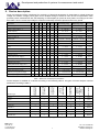
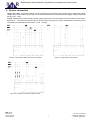
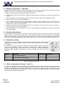
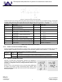
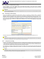
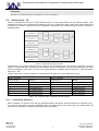
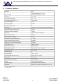
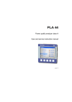
1
Development and production of systems for measurement and control
PLA 33
Power line analyzer
User and service manual
version 2.2
BMR trading
Horní lán 17
779 00 Olomouc
Czech Republic
1
Tel: +420 778 066 566
[email protected]
www.bmr-trading.com
Development and production of systems for measurement and control
Content
1. Front control panel and terminal plate.......................................................................................................................... 3
2. Device description........................................................................................................................................................ 4
3. Device connection........................................................................................................................................................ 5
4. Setting in operation – fast start.................................................................................................................................... 6
5. Function description..................................................................................................................................................... 6
6. Parameter setting......................................................................................................................................................... 6
6.1. Main configuration settings – menu P_1.............................................................................................................. 6
6.1.1.
6.1.2.
6.1.3.
6.1.4.
6.1.5.
Utr – voltage transformer ratio........................................................................................................................................ 7
Itr – current transformer ratio.......................................................................................................................................... 7
Input / output configuration............................................................................................................................................. 7
Power and current demand setting................................................................................................................................ 8
Internal calendar and clock............................................................................................................................................ 8
6.2.1.
6.2.2.
6.2.3.
6.2.4.
6.2.5.
6.2.6.
6.2.7.
Communication interface RS485.................................................................................................................................... 9
System frequency setting............................................................................................................................................... 9
Password protection against unauthorized configuration...............................................................................................9
Display back-light configuration...................................................................................................................................... 9
Reset to the default factory setting...............................................................................................................................10
Recording to flash memory.......................................................................................................................................... 10
Load profile recording................................................................................................................................................... 10
6.2. Second menu P_2............................................................................................................................................... 9
6.3. Alarm menu – AL................................................................................................................................................ 11
6.3.1.
Comparator definition................................................................................................................................................... 11
7. Normal monitoring mode............................................................................................................................................ 12
7.1. Operation and symbol meanings....................................................................................................................... 12
7.2. Maximum and minimum values......................................................................................................................... 12
7.3. Demand values.................................................................................................................................................. 13
7.4. Output status signalization................................................................................................................................. 13
7.5. Energy counters................................................................................................................................................. 13
7.6. Monitoring screens............................................................................................................................................. 14
8. Technical features...................................................................................................................................................... 16
9. Connection of RVM02 module................................................................................................................................... 17
BMR trading
Horní lán 17
779 00 Olomouc
Czech Republic
2
Tel: +420 778 066 566
[email protected]
www.bmr-trading.com
Development and production of systems for measurement and control
1. Front control panel and terminal plate
Picture 1: Front panel description
1.
– key for setup menu entrance and saving set parameters
2.
– cursor key for moving up in menu and parameter change to higher value
3.
– cursor key for moving down in menu and parameter change to lower value
4.
– ESC key for canceling or return
Picture 2: Terminal plate
BMR trading
Horní lán 17
779 00 Olomouc
Czech Republic
3
Tel: +420 778 066 566
[email protected]
www.bmr-trading.com
Development and production of systems for measurement and control
2. Device description
Power line analyzer PLA33 is designed for monitoring of electrical parameters of three-phase or single-phase low
voltage and medium voltage power grids. PLA33 analyzer design is based on fast 16 bits microprocessor which
provides precise measurement with fast sampling of 128 samples per period at each phase. According to the norm
EN 61000-4-30, the current and voltage is measured continually at all three phases and at every period.
Parameter
Σ
L1
L2
L3
Phase voltage, L – N
●
●
●
●
●
●
10 ... 300 VAC
0 ... 180 kV
±0,5 %
Phase to phase voltage, L – L
●
●
●
●
●
●
10 ... 520 VAC
0 ... 312 kV
±0,5 %
System frequency
●
●
●
40 ... 70 Hz
40 ... 70 Hz
±50 mHz
Current
●
●
●
0,01 ... 6 A
0 ... 7,5 kA
±0,5 %
●
●
min max avg Measuring range
Displaying range
Accuracy
Current in neutral, N
●
●
●
-
0 ... 7,5 kA
±0,5 %
Power factor
●
●
●
0,01 ind. ... 0,01 cap.
0,01 ind. ... 0,01 cap.
±1 %
cosφ
●
●
●
●
●
0,01 ind. ... 0,01 cap.
0,01 ind. ... 0,01 cap.
±1 %
THDU
●
●
●
●
●
0 ... 99,9%
0 ... 99,9%
±5 %
THDI
●
●
●
●
●
0 ... 99,9%
0 ... 99,9%
±5 %
Odd harmonics of voltage (1 - 19) in %
●
●
●
●
●
0 ... 99,9%
0 ... 99,9%
±5 %
Odd harmonics of current (1 - 19) in %
●
●
●
●
●
0 ... 99,9%
0 ... 99,9%
±5 %
Apparent power, S
●
●
●
●
●
0 ... 1,8 kVA
0 ... 999 MVA
±0,8 %
Active power take-off / supply, P
●
●
●
●
●
0 ... 1,8 kW
0 ... 999 MW
±0,8 %
Reactive power take-off / supply , Q
●
●
●
●
●
0 ... 1,8 kVAr
0 ... 999 MVAr
±1,0 %
Apparent power, sum S
●
●
●
0 ... 5,4 kVA
0 ... 999 MVA
±0,8 %
Active power take-off / supply, sum P
●
●
●
0 ... 5,4 kW
0 ... 999 MW
±0,8 %
Reactive power take-off / supply, sum Q
●
●
●
0 ... 5,4 kVAr
0 ... 999 MVAr
±1,0 %
Active energy take-off / supply
●
●
0 ... 9 999 999 kWh
0 ... 9 999 999 kWh
Class 1
Reactive (L) energy take-off / supply
●
●
0 ... 9 999 999 kVArh
0 ... 9 999 999 kVArh
Class 2
Reactive (C) energy take-off / supply
●
●
0 ... 9 999 999 kVArh
0 ... 9 999 999 kVArh
Class 2
* for ideal sinusoidal curve of voltage and current
Table 1: Measured and displayed parameters
PLA33 analyzer is available in 8 variants according to the following table 2. All types of PLA33 analyzer measure
parameters according to table 1.
Power supply
voltage 230 VAC
Voltage and
current
measurement
according
EN50160
Mounting variant
●
●
panel
●
●
panel
●
●
●
panel
●
●
●
panel
Supply voltage
power cuts
memory
Internal data
flash memory
Programable
inputs / outputs
Communication
interface RS485
Analyzer type
PLA33 L
PLA33
●
PLA33 C
●
●
PLA33 CM
●
●
●
PLA33DL L
PLA33DL
●
●
DIN rail
●
DIN rail
PLA33DL C
●
●
●
●
DIN rail
PLA33DL CM
●
●
●
●
DIN rail
Table 2: Analyzer types
BMR trading
Horní lán 17
779 00 Olomouc
Czech Republic
4
Tel: +420 778 066 566
[email protected]
www.bmr-trading.com
Development and production of systems for measurement and control
3. Device connection
Default parameters, according to table 3, are set to the device in production. The level and type of used power supply
voltage has to be the same as it is written on the terminal plate label. By default the power supply voltage is 230 VAC
50 Hz (+10%, -15%).
Voltage measurement circuits as well as power supply input have to be connected via circuit breaker or power switch
and fuse (2 ... 10 A) which are placed close to the device for easy access. Current measurement circuits have to be
connected via current transformers, either ../5A or ../1A ratio.
Picture 3: Three-phase measurement at TN-C network
Picture 4: Single-phase measurement
Picture 5: Connection at medium voltage network
BMR trading
Horní lán 17
779 00 Olomouc
Czech Republic
5
Tel: +420 778 066 566
[email protected]
www.bmr-trading.com
Development and production of systems for measurement and control
4. Setting in operation – fast start
Setting PLA33 analyzer in operation is very easy although there is list of parameters than can tune device for various
applications. For fast commissioning of the PLA33 analyzer follow next instructions.
1. Make connection according to connection diagram at picture 3.
2. Connect the right level of power supply voltage according the label on back side of device and turn the power
supply on.
3. Press button SET for the time at least 5 seconds. After that, device will switch to the configuration mode.
4. Enter the menu P_1 by pressing button SET on it.
5. Set the voltage transformer ratio in the parameter Utr in case that voltage transformer is used. Key ▲ is used for
moving in menu. Key Set enable parameter setting. For changing of the ratio value use keys ▲ (+) and ▼ (-).
Newly set ratio confirm by pressing key Set.
6. Set the current transformer ratio in the parameter Itr. For changing of the ratio value use keys ▲ (+) and ▼ (-).
Newly set ratio confirm by pressing key Set.
7. Press the key ESC to close configuration menu P_1. Another pressing of key ESC will turn device back to normal
monitoring operation.
5. Function description
Device digitizes continually (period by period) measured true RMS values of voltage and current in three-phase
network according to the norm EN 50160. Values on the display are updated every second. Maximums of measured
values as well as energy values are stored into nonvolatile memory. For the model PLA33CM with internal 512 MB
flash memory the selected variables are also stored into that memory with the minimum recording period of 200 ms.
6. Parameter setting
Configuration of power line analyzer PLA33 is divided into the three menus. For entering the
configuration mode press key SET for at least 5 seconds. After that following screen appears
on the display.
For moving in the menu use cursor keys ▲ and ▼. Key ▲ is normally used for circle moving
in the menu. Parameters setting is activated by pressing the key SET. Changing the
parameter setting is done by cursor keys ▲ and ▼, confirmation of newly set parameter
value by key SET. Key ESC cancels setting or move back to higher menu or back to normal
operation.
Parameter
Description
Factory setting
Setting range
P_1
main configuration settings
►
►
P_2
communication parameters settings
►
►
AL
alarms settings
►
►
Table 3. Configuration mode menu
6.1. Main configuration settings – menu P_1
In the main configuration menu, it is possible to set essential parameters for correct function of PLA33 analyzer. In
the table 4, there is the list of parameters available at the menu P_1. For moving in the menu use cursor key ▲. By
pressing the key SET enter the parameter configuration where changing the parameter value is possible by cursors
keys ▲ and ▼. Confirmation of set parameter is done by press of key SET. Key ESC cancels the parameter
configuration while keeping initial setting.
BMR trading
Horní lán 17
779 00 Olomouc
Czech Republic
6
Tel: +420 778 066 566
[email protected]
www.bmr-trading.com
Development and production of systems for measurement and control
Parameter
Description
Factory setting
Setting range
Utr
voltage transformer ratio
1
1 ... 1500
Itr
current transformer ratio
1
1 ... 1500
In
K1 1st output / input setting
In
In, Out, PuL, AL
In
K2 2nd output / input setting
In
In, Out, PuL, AL
t_A
time for maximum demand averaging calculation
1 ... 60 min
C_A
power and current demand setting
S_A, F_A
Y--
internal calender – year setting 20--
9
9 ... 99
Π--
internal calender – month setting
1
1 ... 12
d--
internal calender – day setting
1
1 ... 31
h--
internal clock – hour setting
0
0 ... 23
Π--
internal clock – minute setting
0
0 ... 59
ΠA
maximums of measured parameters
OFF
OFF / On
ΠCL
reset of all maximums and minimums
-
-
Table 4. Main configuration menu P_1
6.1.1.
Utr – voltage transformer ratio
If the voltage transformer is used, for example MV applications, according to connection
diagram on picture 5, it is necessary define transformer ratio for correct operation.
It is important to have in mind that the value which is set, is ratio itself. It means that, for
example, if primary voltage 6000 V and secondary voltage is 100 V then set value is 60.
6.1.2.
Itr – current transformer ratio
It is important to have in mind that the value which is set, is ratio itself. It means that, for example, if primary nominal
current of current transformer is 50 A and secondary is 5 A then set parameter value is 10.
Caution
Measurement range of the current inputs is from 10 mA to 6 A. Maximum of the current transformer ratio is 7500/5 A.
6.1.3.
Input / output configuration
Device is equipped by two output / input terminals. Definition how the terminal will behave is
fully programmable. By default terminal behavior as input is set. In the configuration menu
P_1 the setting of input / output terminal is on the third and fourth position. It is represented
by shorter of status and by symbol K1 for input/output No. 1 and by symbol K2 for input/output
No. 2.
Every input/output can be set independently on other. Connection example of combination of
one input and one output is show on the picture 6. Polarity of voltage is changing according to
usage of input or output. Check carefully device label.
BMR trading
Horní lán 17
779 00 Olomouc
Czech Republic
7
Tel: +420 778 066 566
[email protected]
www.bmr-trading.com
Development and production of systems for measurement and control
Picture 6. Connection of PLA 33 input and output
PLA33 can work as an energy meter with pulse outputs. Pulses can represent any of measured energy, consumption
or supply. After selecting of pulse output PuL the requested energy counter is chosen at the second line. Last step is
to define the weight of the pulse output at the third line. Weight is define in range from 1 ... 500 Wh.
Parameter
Description
Factory setting Setting range
In
input controlled by PC
-
-
Out
output controlled by PC
-
-
1
1 ... 500 Wh
PuL
C_P pulse output – active energy consumption
PuL
C_L
pulse output – reactive inductive energy
consumption
1
1 ... 500 Wh
PuL
C_C
pulse output – reactive capacitive energy
consumption
1
1 ... 500 Wh
PuL
S_P pulse output – active energy supply
1
1 ... 500 Wh
PuL
S_L pulse output – reactive inductive energy supply
1
1 ... 500 Wh
PuL
S_C pulse output – reactive capacitive energy supply
1
1 ... 500 Wh
-
definition at chapter 6.3
AL
alarm output
Table 5. Input / Output configuration states
6.1.4.
Power and current demand setting
PLA33 is equipped by demand feature for phase current, three-phase apparent power and three-phase active power.
Demand feature is defined by period for averaging in the parameter t_A which can be set from 1 ... 60 minutes.
Another parameter C_A defines the method for calculation of demand.
Parameter
C_A
6.1.5.
Setting
Description
S_A
static window for averaging according to defined averaging time in parameter t_A
F_A
flow window for averaging with window time defined in parameter t_A
Internal calendar and clock
Versions of PLA33 with communication interface are equipped by
internal real time clock and calender. Setting of the time and date is
available in configuration menu by editing parameters visible on the
two screens.
Moving cursor on the parameter by key ▼ and pressing SET enters
the setting. First screen in order is date setting (Year / Month / Day)
and after pressing the key ▲ the second screen of time setting (Hour /
Minute) will appear.
BMR trading
Horní lán 17
779 00 Olomouc
Czech Republic
8
Tel: +420 778 066 566
[email protected]
www.bmr-trading.com
Development and production of systems for measurement and control
6.2. Second menu P_2
Second menu P_2 groups parameters for communication setting, system frequency and reset to the default factory
setting.
Parameter
Description
Factory setting
Setting range
Id
device identification number in RS485 network
0
0 ... 255
bd
communication speed for data transmission
9,6
9,6 / 19,2 / 38,4 / 57,6 / 115 kBd
PAr
communication control by parity checking
---
--- (none), _o_ (odd), _E_ (even)
St
stop bit
1
1/2
Fr
system frequency
50
50 / 60 Hz
PAS
password
---
any number in the range 001 – 999
bcL
display backlight
60
OFF, 30 ... 900 second
cnt
display contrast
100%
30 ... 100%
rES
reset to default factory setting
S_Π
information about running recording to memory*
Off
On – recording in process
S_P
Information about enabled last profile*
Off
On – recording in process
Hz
Table 6: Second configuration menu P_2
6.2.1.
Communication interface RS485
Device can be equipped by serial interface RS485 for communication with PC or other devices. In the second menu
there is possibility to define communication parameters as they are described in table 6.
Id – identification number defines the number of device in the RS485 network and has to be unique within the
network. bd – communication speed defines communication speed between the PLA33 device and PC. Par – parity
control is by default disabled and it can be changed to even (_E_) or odd (_o_). Communication speed and parity
control has to be identically set to the same values at device and RS485 converter.
6.2.2.
System frequency setting
In order to assure the best performance and measurement accuracy the device is by default tuned to sample voltage
and current in network with system frequency of 50 Hz. Nevertheless it is designed also for systems which works with
60 Hz frequency. To obtain the best performance from PLA33 analyzer set the system frequency according to your
system by editing the parameter Fr.
Caution
System frequency should be changed only in case that the system works in 60 Hz system. Default setting of 50 Hz complies
with system in most of the countries around the world.
6.2.3.
Password protection against unauthorized configuration
Device is possible to be protected against unauthorized configuration changes by three digit password. Entering the
parameter PAS and activating the password setting by key SET opens definition of the first number of password. By
key ▲ number is defined while key ▼ moves cursor to another digit. Password is confirmed by key SET. Erasing the
password is possible by setting the 000.
6.2.4.
Display back-light configuration
Display back-light can be adjust to give the best performance according to light condition at place of installation.
Contrast of display is adjustable by parameter cnt from 30% ... 100% in step of 10%. It is also possible to set the
back-light behaviour. Back-light can be permanently disabled or active only for certain time by parameter bcL. It is
adjustable from 30 ... 900 s, from last activity on the keyboard.
In order to safe energy and reduce the internal self heating the display will turn off after set time.
BMR trading
Horní lán 17
779 00 Olomouc
Czech Republic
9
Tel: +420 778 066 566
[email protected]
www.bmr-trading.com
Development and production of systems for measurement and control
6.2.5.
Reset to the default factory setting
There is possibility to turn PLA33 analyzer back to the default factory setting. In the second menu is available
parameter rES. By pressing the key SET on this parameter, device erases all settings except the real time clock and
calendar and sets default factory setting.
Important
After reset to the default factory setting the all user configurations are lost. It is necessary to set at least transformer ratio of
current and voltage transformer.
6.2.6.
Recording to flash memory
Device PLA33CMB and PLA33DLCM has internal flash memory for recording of average values of measured
parameters. Setting and operation of the measurement is performed from PMS software only. Up to 10 parameters (1
parameter means for example all phase currents) can be recorded with recording interval adjustable from 1 to 60
minutes. Since the measurement is downloaded via RS485 line it is important select proper recording period to limit
the file size for short later download. For example, the recording over the month it is recommended to have recording
period 15 minutes. Time of download to PMS software depends on the communication speed set in device and
converter.
Running measurement is identified in PLA33CMB under informative parameter S_Π and its status On / Off.
Caution
Measurement recording to flash memory is backup-ed for power cuts up to 12 hours length. If the power cut is longer the
measurement recording might be lost or contain some errors and incorrect data.
6.2.7.
Load profile recording
For device PLA33CMB and PLA33DLCM is possible (from PMS software) start load profile recording into two blocks
of flash memory. Recording period is defined by the time of averaging in the parameter t_A and it is adjustable from 1
... 60 minutes. Every t_A time the values or all energy meters are recorded to memory until the reserved space left.
Then the data from complete block are deleted and new recordings are stored.
For example for 15 minutes recording period the two blocks of flash memory are able keep approximately about 80
days of load profile. Keeping the load profile consistent it is necessary to manage regular download of data before
the time left.
Caution
Load profile recording is backup-ed for power cuts up to 12 hours length. If the power cut is longer the load profile data can
be lost and it is necessary create the new load profile by PMS software.
BMR trading
Horní lán 17
779 00 Olomouc
Czech Republic
10
Tel: +420 778 066 566
[email protected]
www.bmr-trading.com
Development and production of systems for measurement and control
Information
This feature is available for device with firmware version 6.0 and higher.
6.3. Alarm menu – AL
Device is equipped by two input / output terminals which can be programmed to the four different states. If the
terminal one or two is set, according to the setting in menu P_1, to work as an alarm output. Every output, while is set
to behave as an alarm, consists from three comparators. Comparators are sorted into logical function according to
following picture.
Picture 7. Comparators and logic functions
Comparators C1, C2 and C3 belongs to the output K1 and comparators C4, C5 and C6 to output K2. From the
picture 7 is visible that there are logical function between first two comparators of the group and between their result
and last comparator of the group. There are two logical operators available, logical conjunction – AND and logical
disjunction – OR.
Logical output can be in also inverted or in normal position. By default it is set to behave as normal.
Ch123 – output K1
Ch456 – output K2
Logical operator
Meaning
Logical operator
Meaning
u_u
(C1 OR C2) OR C3
u_u
(C4 OR C5) OR C6
u_n
(C1 OR C2) AND C3
u_n
(C4 OR C5) AND C6
n_u
(C1 AND C2) OR C3
n_u
(C4 AND C5) OR C6
n_n
(C1 AND C2) AND C3
n_n
(C4 AND C5) AND C6
nor
normal logical output
nor
normal logical output
inr
inverted logical output
inr
inverted logical output
Table 7: List of logical function combination and output states
6.3.1.
Comparator definition
Each comparator can be set to work with any parameter listed in the table 8. Chosen parameter is compared if it is <
or > than set value level. For every comparator there are three screens in the menu AL in the setting mode. By
default every comparator is disabled and introduced by symbol oFF.
BMR trading
Horní lán 17
779 00 Olomouc
Czech Republic
11
Tel: +420 778 066 566
[email protected]
www.bmr-trading.com
Development and production of systems for measurement and control
comparator No. 2
comparator No. 2
comparator No. 2
alarm event U_1
value level
minimum event
duration [s]
minimum time of
output reaction [s]
comparand
Picture 8. Comparator definition screens
At the first screen of appropriate comparator the compared parameter is selected and it is defined the operation.
Second screen defines the value level of compared parameter in real values. Third screen is used for setting the
time of alarm event duration for output activation and minimum time of output reaction. Both times can be set in
range from 0 ... 900 seconds.
Symbol
Description
Symbol
Description
Symbol
Description
U1
phase voltage in L1
U 3 THD
voltage THD in phase L3
11
11th harmonics of voltage
U2
phase voltage in L2
I 1 THD
current THD in phase L1
13
13th harmonics of voltage
U3
phase voltage in L3
I 2 THD
current THD in phase L2
15
15th harmonics of voltage
U 1-2
phase to phase voltage L1 – L2
I 3 THD
current THD in phase L3
17
17th harmonics of voltage
U 1-3
phase to phase voltage L1 – L3
1 cosφ
cosφ in phase L1
19
19th harmonics of voltage
U 2-3
phase to phase voltage L2 – L3
2 cosφ
cosφ in phase L2
harmonics available for all phases
I1
current in phase L1
3 cosφ
cosφ in phase L3
S
three-phase active power
I2
current in phase L2
Fr
system frequency
P
three-phase apparent power
I3
current in phase L3
3
3 harmonics of voltage
L
three-phase L reactive power
In
current in N wire
5
5th harmonics of voltage
C
three-phase C reactive power
U 1 THD
voltage THD in phase L1
7
7th harmonics of voltage
A_P
three-phase average active power
U 2 THD
voltage THD in phase L2
9
9 harmonics of voltage
123cosφ
three-phase power factor
rd
th
Table 8. List of available alarm events
7. Normal monitoring mode
Standard operation status of the device is monitoring of electrical parameters. Monitored parameters are logically
grouped and shown within one screen and sort to the set of related screens. There are 8 groups or better say levels
according to the chapter 7.5.
7.1. Operation and symbol meanings
Display of the device is multifunction with symbols which introduce and specify shown information. Movement
between groups (levels) of related screens is by pressing the key ▲. Within the (group) level, particular screens are
browsed by pressing the key ▼. Levels are not closed so when the last screen of the currently displayed level is
reached, other press of key ▼ moves to the first screen of next level.
From any screen at any level it is possible turn back to the first screen (phase voltage) by pressing the key ESC.
7.2. Maximum and minimum values
For all measured parameters the maximum reached values are kept in the memory. For several parameters the
minimum of measured value is kept too. For presenting the maximum value one short press of key SET is needed.
Maximum values are symbolized by symbol ▲ before the displayed number. Second short press of key SET displays
the minimum values if available. Minimum values are symbolized by symbol ▼ before the displayed number. Third
short press of key SET will turn back to the instantaneous measurement.
BMR trading
Horní lán 17
779 00 Olomouc
Czech Republic
12
Tel: +420 778 066 566
[email protected]
www.bmr-trading.com
Development and production of systems for measurement and control
7.3. Demand values
For displaying the demand values of phase current, three-phase
apparent power and three-phase active power it is necessary go to
the screen of appropriate parameter and press the key SET twice.
Demand value is introduced by displayed symbols ▲ and ▼ at the
same time.
Since the demand value is four-quadrant the demand value of
consumption is introduced only by symbols ▲ and ▼. For distribution
the value is introduced by negative sign between symbols ▲ and ▼.
7.4. Output status signalization
Outputs can be operated in four states. Signalization on the LCD is common for all of them and differs according to
following table.
Parameter
Description
Activated
In
input
Out
output
PuL
pulse output
at pulse presence
AL
alarm output
flashing
Deactivated
7.5. Energy counters
PLA33 measures all energies in consumption and supply direction, so there are six counters
divided to the two groups. First group of three counters (active energy, reactive inductive
energy, reactive capacitive energy) is for consumed energy and it is introduced by symbol ▲
shown on the first line of displayed total energy number.
Second group of three counters (active energy, reactive inductive energy, reactive capacitive
energy) is for supplied energy and it is introduced by symbol ▼ shown on the first line of
displayed total energy number.
Note
Erasing of all energy counters is possible in the configuration menu P_2 by simultaneous pressing of buttons ▲ and ▼ or
from PC by usage of PMS software.
BMR trading
Horní lán 17
779 00 Olomouc
Czech Republic
13
Tel: +420 778 066 566
[email protected]
www.bmr-trading.com
Development and production of systems for measurement and control
7.6. Monitoring screens
Meaning of each screen is easily identified by usage of standard ISO symbols and value parameters. Every
displayed parameter value is shown with its variable.
Phase voltage
Phase to phase voltage
▼
Voltage THD
3rd voltage harmonics
▼
▼
19th voltage harmonics
..
▼..
▲
Phase current
Current in neutral
▼
Current THD
3rd current harmonics
▼
▼
19th current harmonics
..
▼..
▲
System frequency
▲
Cos φ
Power factor
▼
▲
BMR trading
Horní lán 17
779 00 Olomouc
Czech Republic
14
Tel: +420 778 066 566
[email protected]
www.bmr-trading.com
Development and production of systems for measurement and control
▲
Apparent power
Reactive inductive
power
Active power
▼
▼
Reactive capacitive
power
▼
▲
Apparent three-phase
power
Active three-phase
power
▼
Reactive inductive
three-phase power
▼
Reactive capacitive
three-phase power
▼
▲
Active energy –
consumption
Reactive L energy –
consumption
▼
Reactive C energy consumption
▼
▲
Reactive L energy –
supply
Active energy – supply
▼
BMR trading
Horní lán 17
779 00 Olomouc
Czech Republic
Reactive C energy supply
▼
15
Tel: +420 778 066 566
[email protected]
www.bmr-trading.com
Development and production of systems for measurement and control
8. Technical features
Parameter
Value
Supply voltage
230 VAC, 50/60 Hz (+10%,-15%)
24 V DC/AC (for variant ...V24)
Frequency
45 ... 65 Hz
Current measuring range
0,01 ... 6 A
Voltage measuring range L - N
10 ... 300 VAC
Power consumption
1,5 VA
Sampling frequency
6,4 kHz
Number of output / input
2
Output type
Open collector, free potential optical insulated (S0)
Maximum voltage for output usage
24 VDC
Maximum output load capability
100 mA
Input type
optical insulated free potential
Maximum input voltage
24 VDC
Maximum input consumption
10 mA
Voltage and current transformer ratio
1 ... 1500
Supply voltage power cuts memory
20 events *
Data memory for measured parameters
512 MB **
Communication port
RS485 (optional) *
Communication protocol
MODBUS RTU *
Communication speed
9,6 / 19,2 / 38,4 / 57,6 / 115 kBd *
Over-voltage class
300 V CAT III
Pollution degree
2
Temperature limit
-25°C ... +60°C
Front panel (DL variant front size)
96 x 96 mm (90 x 87 mm)
Panel cutout
92 x 92 mm
Site depth (DL variant depth)
55 mm (58 mm)
Weight
620 g (including packaging)
Protection degree
IP20 rear cover / IP54 front panel
Standards
EN 61010-1, EN 60947-1, EN 61000-6-2, 2-4, 6-3
* only PLA33C and PLA33CM variant
** only PLA33CM variant
BMR trading
Horní lán 17
779 00 Olomouc
Czech Republic
16
Tel: +420 778 066 566
[email protected]
www.bmr-trading.com
Development and production of systems for measurement and control
9. Connection of RVM02 module
For application where there is a need of relay output the expansion module RVM02 is available option. It is equipped
by 2 relay outputs with 250 VAC / 440 VAC / 16 A contacts.
Picture 8. Connection of RVM02 to PLA33
Note
While the RVM02 expansion relay output module is used the PLA33 outputs should be set on function as an alarm outputs or
outputs controlled by Modbus command.
BMR trading
Horní lán 17
779 00 Olomouc
Czech Republic
17
Tel: +420 778 066 566
[email protected]
www.bmr-trading.com