1
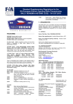
MRA3P
version 1.3
3-phase monitoring relay with fault diagnostic
1. Device description
Device is designed to monitor succession of phases (L1, L2, L3), phase failure of any of phases and to control phase
asymmetry. Relay is equipped with visual fault diagnosis. MRA3P is mainly designed for protection of three-phase
motors. Relay has one output double-throw contact 8 A.
Important
In the case of 3 wire connection, internal over-voltage protection does not work and lifetime of the device can be reduced.
However, if this is the way how relay is connected, then it is recommended to use external phase over-voltage fault protection,
but not in the system with insulated tie-down point.
Terminal description:
Terminal placement:
Connection diagram:
Supply / controlled voltage
Fault diagnostic
Supply voltage indication
Phase asymmetry setting.
Position “0FF” disconnects
asymmetry detection.
Outputs
2. Function
After connection to the supply voltage green LED turns
ON. If all phases are present, together with correct
sequence and if the asymmetry is within the preset
limit, then relay will switch the output (contact No. 15 –
18) and red LED will turn off. In the case there is a fault
of any of phases or asymmetry is over preset limit, red
LED signalizes error type and relay will switch off the
output (contact No. 15 – 16). Any voltage drop below
165 V is considered to be a phase failure. Detection
and failure reaction is shorter then 100 ms.
3. LED diagnostic
Green LED on:
Presence of supply voltage.
Green LED off:
Supply voltage is not present.
Red LED on:
Fault condition detected: irregular phase sequence. Contact No.15-16 closed.
Red LED blinking:
Fault condition detected: phase asymmetry. Contact No.15-16 closed.
Red LED blinking 1x:
Fault condition detected: phase 1 failure. Contact No.15-16 closed.
BMR
Balbínova 252
516 01 Rychnov n. Kn.
Czech Republic
BMR export
Horní lán 17
77900 Olomouc
Czech Republic
1
Tel: +420 774 415 703
[email protected]
www.bmr.cz
Development and production of systems for measurement and control
Red LED blinking 2x:
Fault condition detected: phase 2 failure. Contact No.15-16 closed.
Red LED blinking 3x:
Fault condition detected: phase 3 failure. Contact No.15-16 closed.
Red LED off:
Error condition not detected. Contact No. 15-18 closed.
4. Technical features
Parameter
Value
Supply / controlled terminals:
L1, L2, L3, N
Supply / controlled voltage:
3 x 400 V / 230 V
Power consumption:
max. 1,5 VA
Supply voltage indication:
green LED
Maximum controlled voltage (to N):
269 V
Toggle level (fix):
165 V
Hysteresis:
fix 5 %
Asymmetry (adjustable):
5 - 20 %
Asymmetry disconnection (adjustable):
OFF position
Output parameters:
Number and type of contacts:
1x changeover contact
Nominal current:
8A
Switching power:
max. AC 2000 VA
Trigger current:
30 A
Nominal voltage / max. switching voltage:
250 VAC / 440 VAC
Mechanical lifetime:
3 x 10⁷
Electrical lifetime:
1 x 10⁵ 250 VAC, 8 A
Others:
Working temperature:
-20 .. +55 °C
Storage temperature:
-40 .. +70 °C
Working position:
any
Mounting:
IEC 60715 (DIN 35)
Protection degree:
IP 40 on panel / IP 20 terminals
Electrical strength:
4 kV
Input wire diameter with/without cavern:
max. 2x1,5mm2; 1x2,5mm2 / max. 2x1,5mm2; 1x2,5mm2
Weight:
75 g
Dimensions:
90 x 18 x 65 mm
Standards:
IEC 60255-6, IEC 61010
BMR
Balbínova 252
516 01 Rychnov n. Kn.
Czech Republic
BMR export
Horní lán 17
77900 Olomouc
Czech Republic
2
Tel: +420 774 415 703
[email protected]
www.bmr.cz