1
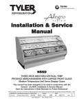
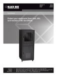
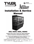
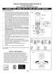
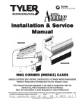
Installation & Service
Manual
LDSSI
SELF-SERVICE DELI ISLAND MERCHANDISER
Medium Temperature Self Serve Display Cases
This manual has been designed to be used in conjunction with the General
(UL/NSF) Installation & Service Manual.
Save the Instructions in Both Manuals for Future Reference!!
This merchandiser conforms to the American National Standard Institute & NSF International Health and Sanitation standard ANSI/NSF 7 - 1999.
PRINTED IN Specifications subject to REPLACES
IN U.S.A.
change without notice. EDITION
ISSUE
DATE
5/04
Tyler Refrigeration * Niles, Michigan 49120
PART
NO.
9805002
REV.
LDSSI
Tyler Refrigeration
CONTENTS
Page
Specifications
LDSSI Specification Sheets . . . . . . . . . . . . . . . . . . . . . . . . . . . . . . 4
Line Sizing Requirements . . . . . . (See General-UL/NSF I&S Manual)
Pre-Installation Responsibilities . . . . . (See General-UL/NSF I&S Manual)
Installation Procedures
Carpentry Procedures . . . . . . . . . . . . . . . . . . . . . . . . . . . . . . . . . 5
Plumbing Procedures . . . . . . . . (See General-UL/NSF I&S Manual)
Refrigeration Procedures . . . . . (See General-UL/NSF I&S Manual)
Electrical Procedures . . . . . . . . . . . . . . . . . . . . . . . . . . . . . . . . . . 5
Electrical Considerations . . . . . . . . . . . . . . . . . . . . . . . . . . . . . . . . 5
Defrost Information . . . . . . . . . . . . . . . . . . . . . . . . . . . . . . . . . . . . 5
Defrost Control Chart . . . . . . . . . . . . . . . . . . . . . . . . . . . . . . . . . . . 5
Installation Procedure Check Lists (See General-UL/NSF I&S Man.)
Wiring Diagrams . . . . . . . . . . . . . . . . . . . . . . . . . . . . . . . . . . . . . . . . . . . 6
LDSSI Domestic & Export (50Hz) Case Circuits . . . . . . . . . . . . . . . 6
Cleaning and Sanitation . . . . . . . . . . . (See General-UL/NSF I&S Manual)
Component Removal and Installation Instructions for Cleaning 7
Screens . . . . . . . . . . . . . . . . . . . . . . . . . . . . . . . . . . . . . . . . . . . . . 7
Bottom Trays . . . . . . . . . . . . . . . . . . . . . . . . . . . . . . . . . . . . . . . . . 7
Discharge Air Honeycomb . . . . . . . . . . . . . . . . . . . . . . . . . . . . . . . 7
Rear Air Duct Panels . . . . . . . . . . . . . . . . . . . . . . . . . . . . . . . . . . 7
Front Air Ducts Panels . . . . . . . . . . . . . . . . . . . . . . . . . . . . . . . . . 7
Base Access Panel . . . . . . . . . . . . . . . . . . . . . . . . . . . . . . . . . . . . 7
Plexiglas Care . . . . . . . . . . . . . . . . . . . . . . . . . . . . . . . . . . . . . . . 7
Cleaning . . . . . . . . . . . . . . . . . . . . . . . . . . . . . . . . . . . . . . . . . . . . 7
Waxing . . . . . . . . . . . . . . . . . . . . . . . . . . . . . . . . . . . . . . . . . . . . . 7
Page 2
May, 2004
Installation & Service Manual
LDSSI
Page
General Information
NSF Product Thermometer Installation . . . . . . . . . . . . . . . . . . . . 8
Radiant Heat Information . . . . . . . . . . . . . . . . . . . . . . . . . . . . . . . 8
Radiant Heat Measurement . . . . . . . . . . . . . . . . . . . . . . . . . . . . . . 8
Display Practices . . . . . . . . . . . . . . . . . . . . . . . . . . . . . . . . . . . . . . 8
Service Instructions
Preventive Maintenance . . . . . . (See General-UL.NSF I&S Manual)
Fan Blade and Motor Replacement (See General-UL/NSF I&S Man.)
NSF Product Thermometer Replacement . . . . . . . . . . . . . . . . . . 9
Perimeter Plexiglas Replacement . . . . . . . . . . . . . . . . . . . . . . . . 9
Bumper Replacement . . . . . . . . . . . . . . . . . . . . . . . . . . . . . . . . . 10
Lower Access Panel Removal . . . . . . . . . . . . . . . . . . . . . . . . . . 10
Parts Information
Operational Parts List . . . . . . . . . . . . . . . . . . . . . . . . . . . . . . . . . 11
TYLER Warranty . . . . . . . . . . . . . . . . . (See General-UL/NSF I&S Manual)
The following Medium Temperature Self-Service Deli Island Merchandiser models
are covered in this manual:
MODEL
DESCRIPTION
LDSSI
8’ SELF-SERVICE DELI ISLAND MERCHANDISER
LDSSI
12’ SELF-SERVICE DELI ISLAND MERCHANDISER
May, 2004
Page 3
LDSSI
Tyler Refrigeration
SPECIFICATIONS
LDSSI Self-Service Medium Temperature Deli Island Merchandisers
Page 4
May, 2004
Installation & Service Manual
LDSSI
INSTALLATION PROCEDURES
Carpentry Procedures
Defrost Information
The LDSSI models do not require any specific
carpentry procedures. The cases are shipped
as complete islands. Make sure the floor is
level where the cases are to be installed.
Electrical, refrigeration and drain access
should be located under the cases.
See “General-UL/NSF I&S Manual” for
operational descriptions for each type of
defrost control.
Defrost Control Chart
After island case is installed, install the bottom
trays, the case screens and the base access
panel.
Defrost
Defrost Defrosts Duration
Per Day
(Min)
Type
Off Time
4
40
Refrigeration Procedures
WIRING DIAGRAMS
See “General-UL.NSF I&S Manual” for
general system, control and superheat
information.
Electrical Procedures
Electrical Considerations
CAUTION
Make sure all electrical connections are
tight. This prevents burning of electrical
terminals and/or premature component
failure.
Term.
Temp.
-----
ELECTRICIAN NOTE - OVERCURRENT
PROTECTION
120V circuits should be protected by 15 or 20 Amp
devices per the requirements noted on the cabinet
nameplate or the National Electrical Code, Canadian
Electrical Code - Part 1, Section 28. 208V defrost
circuits employ No. 12 AWG field wire leads for field
connections. On remote cases intended for end to
end line-ups, bonding for ground may rely upon the
pull-up bolts.
The following wiring diagram on page 6
covers all the LDSSI case circuits.
NOTE
The electrical box, behind the base access
panel, houses the electrical terminal block
and wiring for the case. The electrical box
covers will be shipped loose.
Case Fan Circuit
This circuit is to be supplied by an uninterrupted, protected 120V circuit. The case fan
circuit is not cycled.
May, 2004
Page 5
LDSSI Domestic & Export (50Hz) Case Circuits (8’ & 12’ Island Cases)
Page 6
May, 2004
Installation & Service Manual
LDSSI
CLEANING AND SANITATION
Front Air Duct Panels
Component Removal and
Installation Instructions for
Cleaning
1. Remove screens and bottom trays, see
this page.
Screens
3. After cleaning, replace in reverse order.
1. Remove product from screens.
Base Access Panel
2. Push screens back until front screen tabs
clear the holes in the front duct.
3. Remove screens from holes in rear duct
panels and from case.
4. After cleaning, replace in reverse order.
Bottom Trays
1. Remove product and screens from case.
See this page.
2. Grasp and lift out each of the bottom trays
from the case interior.
3. After cleaning, replace in reverse order.
2. Remove screws and front air duct panels
from case.
NOTE
Note position of the base access panel
during removal so it can be reinstalled the
same way.
1. Remove screws and base access panel
from lower front section of the case.
2. After cleaning base access panel and
under the case, replace the base access
panel and secure with screws.
Plexiglas Care
Cleaning
Discharge Air Honeycomb
1. Remove screws and bottom retainer strip
from rear interior of case.
NOTE
Note position of the honeycomb grid during
removal so it can be reinstalled the same
way.
2. Remove honeycomb grid sections from the
rear duct.
CAUTION
Improper installation of the honeycomb grid
section could result in improper air flow
and/or poor refrigeration.
3. After cleaning, replace honeycomb grid
sections as they were removed and secure
with the bottom retainer strip and screws.
Rear Air Duct Panels
1. Remove screens, bottom trays and discharge air honeycomb, see this page.
CAUTION
DO NOT use paper towels, soft cloths,
sponges or chamois to clean plexiglas.
These materials will scratch the acrylic
surface.
Clean with lukewarm water and plenty of
nonabrasive soap, or detergent. Use only
bare hand to dislodge any caked-on dirt.
Lightly dry with a clean damp chamois or
clean soft cloth.
Waxing
Wax should be applied in a thin even coat,
and brought to a high polish by rubbing
lightly with a dry clean soft cloth. Excessive
rubbing may cause scratching and/or buildup
an electrostatic charge, which attracts dust
and dirt to the surface. Electrostatic charge
can be removed by blotting acrylic surface
with a clean damp cloth.
2. Remove mounting screws from rear duct
panel.
3. After cleaning, replace in reverse order.
May, 2004
Page 7
LDSSI
Tyler Refrigeration
GENERAL INFORMATION
NSF Product Thermometer
Installation
Product Thermometer
Install and secure a new product thermometer with two screws below the return air duct
on the left end of the case.
Radiant Heat Information
the cases. A dial thermometer stuck into the
center of a piece of meat compared with one
in the air stream quickly confirms this fact.
Another fact is that the surface temperature
of the meat will be higher than the center
temperature due to radiant heat. TYLER’s
ongoing research identifies sources of radiant
heat and accurately measures and records it.
These charts were developed from the
information gathered during this research.
Two major sources of radiant heat are from
display lights and ceiling surfaces.
Additional heat sources come from bad
display practices which either overload the
case with product or allow voids in the
product display. Poor display practices
impair the efficiency of the refrigeration,
adding to the surface temperature of the
meat. Bacteria and molds grow when
surface temperatures rise above 45°F. This
prematurely discolors displayed meats and
causes unnecessary meat department losses.
Radiant Heat Measurement
Place two accurate dial thermometers side by
side in a case. Cover one of the thermometer
stems with black friction tape. The temperature difference is the approximate amount of
radiant heat. A change in display lighting or
a reduction of high ceiling temperatures (over
80°F) could reduce the radiant heat in the
case.
Display Practices
Encourage butchers to
maintain all meat
below the case load
lines and to eliminate
product voids. Case
screens could be covered in some instances to keep the refrigerated air over the display.
A wide temperature range is shown for each
type of lighting. This data does not show all
situations. Many situations will have higher
package warm-up figures than indicated.
It is generally known that the temperature of
displayed meat in refrigerated cases will run
higher than the circulated air temperature of
Page 8
CAUTION
The quality damage done to meat products
by high temperatures and/or contamination
during delivery, cooler storage, cutting and
wrapping cannot be repaired by placing
the products into properly operating
display cases.
May, 2004
Installation & Service Manual
SERVICE INSTRUCTIONS
See “General-UL/NSF I&S Manual” for fan
blade and motor replacement.
NSF Product Thermometer
Replacement
Product Thermometer
LDSSI
5. Position and align new section of plexiglas in the opening and set bottom of
plexglas in lower track.
CAUTION
Avoid cement touching clear plexiglas surfaces. If contact occurs, the surface will
scar and the final appearance may be
unsatisfactory.
6. Using a downing fixture, align the top
edge of plexiglas joint seam. Carefully
apply acrylic adhesive (Weldon #1802) to
joint seam from the outside surface of the
plexiglas. Let adhesive dry for 5 minutes.
7. Using the same downing fixture, drill a
1/4” hole through the top of the plexigals
joint seam. Remove the downing fixture.
1. Remove two screws and the product
thermometer from location below the
left front return air duct on the case.
2. Install and secure the new product
thermometer with two screws on the
case in the same location as it was
previously installed.
8. Apply acrylic adhesive to 1/4” acrylic
dowel pin and insert the pin in top hole.
Let acrylic adhesive dry for 5 minutes,
then cut off excess dowel pin and file
smooth.
Plexiglas Finishing Procedure
Perimeter Plexiglas Replacement
1. If joint seam of plexiglas does not match
perfectly, grind uneven seam with #36 grit
disc until seam is even. The finish area
should be approximately 4 inches wide.
Perimeter plexiglas comes in four sections.
Each section runs the top perimeter of 1/4 of
the case. After installation, the four sections
are adhered together into one piece.
3. Repeat step 2 using #280 grit sand paper.
1. Carefully cut apart sections of plexiglas at
the joints. Remove broken or
damaged plexiglas.
CAUTION
Make sure ends of adjoining plexiglas are
clean and dry.
2. Dry sand using #80 grit sand paper.
Increase width of finish area approximately 1/4” on each side.
4. Repeat step 2 using #400 grit sand paper.
5. Wet sand finish area using #800 grit sand
paper.
6. Repeat step 5 using #1000 grit sand
paper.
7. Repeat step 5 using #1500 grit sand
paper.
3. Using a sanding block, sand all adjoining
edges of plexiglas to ensure, smooth
even edges.
8. Using a buffer, apply Novus
brand heavy scratch remover #3 until
smooth.
4. Measure and cut replacement section of
the plexiglass, if necessary, to approximately 1/4” longer then opening. Block
sand edges to make sure they are even
and smooth.
9. Repeat step 8 using Novus
brand fine scratch remover #2.
May, 2004
10. Polish the finish area using a clean soft
cloth and Novus brand Plastic Clean and
Shine #1.
Page 9
LDSSI
Bumper Replacement
Tyler Refrigeration
NOTE
The center of the second piece of bumper
may need to be snapped into place with a
wooden block and a hammer.
6. Starting at both ends and working
towards the center, snap the second
piece of bumper (3) onto the bumper
retainer (2).
1. Find the bumper joint and pry one end of
the bumper (1) until it start to release
from the bumper retainer (2).
2. Grasp the loose end of the bumper (1)
and pull firmly to peel bumper (1) off the
bumper retainer (2).
3. Use old bumper as a guide to cut new
bumper to the proper length.
4. Starting at one end, snap the new
bumper (1) onto the bumper retainer (2).
5. If more than one piece of bumper needs
to be used to completely go around the
case, measure and cut the second piece
of bumper (3) 1/4” longer than the
remaining space between the bumper
ends.
Page 10
NOTE
Bumpers will shrink when the cases are at
operating temperature.
Lower Access Panel
There are two lower access panels on this
case; one on the front base and one on the
rear base. Both of these panel provide
access to the drain and/or refrigeration lines
to this caes. They also provide access for
cleaning under the case.
1. To remove a lower access panel, remove
six screws and lower access panel (1)
from the base (2) of the case.
2. After completing case maintenance
and/or cleaning under the case, replace
the lower access panel (1) and secure to
base (2) with screws.
May, 2004
Installation & Service Manual
LDSSI
PARTS INFORMATION
Operational Parts List
Case Usage
Domestic
Electrical Circuit
115 Volt 60 Hertz
Case Size
8’
12’
Fan Motor
5125532
5 Watt
5125532
5 Watt
Fan Motor Brackets
5962269
5962269
Fan Bracket Plate
9041077
9041077
Fan Blades (7.00” 15° 5B)
5223891
5223891
Opt. ECM Fan Motor
9025002
8 Watt
9025002
8 Watt
Opt. ECM Fan Motor Brackets
5205005
5205005
Opt. ECM Fan Blades (7.00” 20° 5B)
5960943
5960943
NSF Product Thermometer
5967100
5967100
For information on operational parts not listed above contact the TYLER Service Parts
Department.
May, 2004
Page 11