1
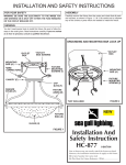
Installation & Service
Manual
LD48, LD54, LD60, LD72
MULTI-DECK SELF-SERVICE DELI MERCHANDISERS
Medium Temperature Refrigerated Display Cases
This manual has been designed to be used in conjunction with the
General (UL/NSF) Installation & Service Manual.
Save the Instructions in Both Manuals for Future Reference!!
This merchandiser conforms to the American National Standard Institute & NSF International Health and Sanitation standard ANSI/NSF 7 - 2003.
PRINTED IN Specifications subject to REPLACES
IN U.S.A.
change without notice. EDITION
10/05
ISSUE
DATE
4/07
Tyler Refrigeration * Niles, Michigan 49120
PART
NO.
9807020
REV.
A
LD48, LD54, LD60, LD72
CONTENTS
Page
Specifications
LD48/LD54/LD60/LD72 Specification Sheets . . . . . . . . . . . . . . . . . . 4
Pre-Installation Responsibilities . . . . . (See General-UL/NSF I&S Manual)
Installation Procedures
Carpentry Procedures . . . . . . . . . . . . . . . . . . . . . . . . . . . . . . . . . . . 6
Case Pull-Up Locations . . . . . . . . . . . . . . . . . . . . . . . . . . . . . . . . . . 6
Electrical Procedures . . . . . . . . . . . . . . . . . . . . . . . . . . . . . . . . . . . . 6
Electrical Considerations . . . . . . . . . . . . . . . . . . . . . . . . . . . . . . . . . . 6
Plumbing Procedures . . . . . . . . (See General-UL/NSF I&S Manual)
Refrigeration Procedures . . . . . (See General-UL/NSF I&S Manual)
Defrost Information . . . . . . . . . . . . . . . . . . . . . . . . . . . . . . . . . . . . . 6
Defrost Control Chart . . . . . . . . . . . . . . . . . . . . . . . . . . . . . . . . . . . . 6
Installation Procedure Check Lists (See Gen.-UL/NSF I&S Manual)
Wiring Diagrams . . . . . . . . . . . . . . . . . . . . . . . . . . . . . . . . . . . . . . . . . . . . 6
LD48/LD54/LD60/LD72 Domestic & Export (50Hz) 4’ Case Circuits 7
LD48/LD54/LD60/LD72 Dom. & Exp. (50Hz) 6’ & 8’ Case Circuits . 8
LD48/LD54/LD60/LD72 Domestic & Export (50Hz) 12’ Case Circuits 9
Cleaning and Sanitation . . . . . . . . . . . . (See General-UL/NSF I&S Manual)
Component Removal and Installation Instructions for Cleaning 10
Shelves and Shelf Brackets . . . . . . . . . . . . . . . . . . . . . . . . . . . . . . . 10
Bottom Trays . . . . . . . . . . . . . . . . . . . . . . . . . . . . . . . . . . . . . . . . . . 10
Front Air Ducts . . . . . . . . . . . . . . . . . . . . . . . . . . . . . . . . . . . . . . . . 10
Rear Duct Panels . . . . . . . . . . . . . . . . . . . . . . . . . . . . . . . . . . . . . . 10
Discharge Air Honeycomb . . . . . . . . . . . . . . . . . . . . . . . . . . . . . . . . 10
Top Duct . . . . . . . . . . . . . . . . . . . . . . . . . . . . . . . . . . . . . . . . . . . . 10
Front Cladding . . . . . . . . . . . . . . . . . . . . . . . . . . . . . . . . . . . . . . . . 11
Page 2
April, 2007
Installation & Service Manual
LD48, LD54, LD60, LD72
Page
General Information
NSF Product Thermometer . . . . . . . . . . . . . . . . . . . . . . . . . . . . . . 11
Service Instructions
Preventive Maintenance . . . . . . (See General-UL/NSF I&S Manual)
Light Servicing
Ballast and Lighting Locations . . . . . . . . . . . . . . . . . . . . . . . . . . . . . 11
Fan Blade and Motor Replacement (See Gen.-UL/NSF I&S Manual)
Color Band and Bumper Replacement (See Gen.-UL/NSF I&S Man.)
Parts Information
Cladding and Optional Trim Parts List . . . . . . . . . . . . . . . . . . . . . 12
Operational Parts List . . . . . . . . . . . . . . . . . . . . . . . . . . . . . . . . . . 14
TYLER Warranty . . . . . . . . . . . . . . . . . (See General-UL/NSF I&S Manual)
The following Multi-Deck, Self-Service, Medium Temperature Deli Merchandiser models
are covered in this manual:
MODELS
DESCRIPTION
LD48
4’, 6’, 8’ & 12’ MULTI-DECK SELF-SERVICE DELI MERCHANDISERS
LD54
4’, 6’, 8’ & 12’ MULTI-DECK SELF-SERVICE DELI MERCHANDISERS
LD60
4’, 6’, 8’ & 12’ MULTI-DECK SELF-SERVICE DELI MERCHANDISERS
LD72
4’, 6’, 8’ & 12’ MULTI-DECK SELF-SERVICE DELI MERCHANDISERS
October, 2005
Page 3
LD48, LD54, LD60, LD72
SPECIFICATIONS
LD48/LD54/LD60/LD72 Multi-Deck Self-Service Deli Merchandisers
Page 4
April, 2007
Installation & Service Manual
April, 2007
LD48, LD54, LD60, LD72
Page 5
LD48, LD54, LD60, LD72
INSTALLATION PROCEDURES
Carpentry Procedures
Case Pull-Up Locations
Case Fan Circuit
This circuit is to be supplied by an uninterrupted, protected 120V circuit. The case fan
circuit is not cycled during defrost on any of
these models.
Fluorescent Lamp Circuit
LD case lighting is supplied by T-8 electronic
ballast lights. It is controlled by a light switch
in each case. The standard lighting is 1-row
of T-8 canopy lights. Optional T-8 shelf lights
are also available on the LD cases. Up to 3
rows on the LD48 and LD54; up to 4 rows on
the LD60; and up to 5 rows on the LD72
models.
Defrost Information
See “General-UL/NSF I&S Manual” for
operational descriptions for Off Time
defrost control.
Defrost Control Chart
Defrost
Defrost
Defrosts Duration
Per Day
(Min)
Type
LD(48/54/60/72)
Off Time
6
20
Term.
Temp.
-----
WIRING DIAGRAMS
The LD models have three pull-ups at each
end of the case. Pull-ups A, B and C are
located as shown and should be installed and
tightened starting with A and finishing with C.
See “General-UL/NSF I&S Manual” for
line-up assembly instructions.
Electrical Procedures
Electrical Considerations
CAUTION
Make sure all electrical connections at
components and terminal blocks are tight.
ELECTRICIAN NOTE - OVERCURRENT
PROTECTION
120V circuits should be protected by 15 or 20 Amp
devices per the requirements noted on the cabinet
nameplate or the National Electrical Code, Canadian
Electrical Code - Part 1, Section 28. 208V defrost
circuits employ No. 12 AWG field wire leads for field
connections. On remote cases intended for end to
end line-ups, bonding for ground may rely upon the
pull-up bolts.
The following wiring diagrams on pages 7
thru 9 will cover the LD48, LD54, LD60 and
LD72 case and lighting circuits.
NOTE
Since the ront cladding is shipped loose,
the wiring has immediate access.
Page 6
April, 2007
LD48/54/60/72 Domestic & Export (50Hz) Case Circuits (4’ Cases)
October, 2005
Page 7
LD48/54/60/72 Domestic & Export (50Hz) Case Circuits (6’ & 8’ Cases)
Page 8
April, 2007
LD48/54/60/72 Domestic & Export (50Hz) Case Circuits (12’ Cases)
October, 2005
Page 9
LD48, LD54, LD60, LD72
CLEANING AND SANITATION
Component Removal and Installation Instructions for Cleaning
Shelves and Shelf Brackets
1. Remove product from shelves.
2. If shelf has a light, unplug the light cord
from the socket in the rear duct panel.
Completely insert socket cover in the light
socket to protect the receptacle.
3. Push shelves back and then lift up and out
to remove them from the shelf brackets.
4. Remove shelf brackets from slots in rear
uprights.
5. After cleaning, replace in reverse order.
Bottom Trays
4. Disconnect shelf harness connector and
complete removing the rear duct panel.
WARNING
Rear duct panels with electrical receptacles can be cleaned without removing the
electrical receptacles. Do not get moisture
on electrical wires when cleaning under
this cover. Moisture on wires could cause
premature product failure and/or personal
injury or death from electrical shock.
5. After cleaning, reconnect the shelf harness connector: install the top socket
assembly: replace and secure rear duct
panels in reverse order.
Discharge Air Honeycomb
1. Loosen screws securing rear retainer
plate.
NOTE
1. Remove product from bottom of case.
2. Grasp and lift out each of the bottom trays
from the case interior.
3. After cleaning, replace in reverse order.
Front Air Ducts
1. Remove lower trays, see this page.
Note position of the honeycomb grid during removal so it can be reinstalled the
same way.
2. Slide rear retainer plate back until the
honeycomb grid sections can be removed
from the top duct.
CAUTION
2. Lift out front air duct sections.
3. After cleaning, replace in reverse order.
Rear Duct Panels
(w/o Shelf Light Sockets)
1. Remove shelves and bottom trays, see
above.
2. Remove mounting screws and rear duct
panels from case.
Improper installation of the honeycomb
grid section could result in improper air
flow and/or poor refrigeration.
3. After cleaning, replace honeycomb grid
sections as they were removed and
secure with the rear retainer plate and
screws.
Top Duct
3. After cleaning, replace and secure rear
duct panels in reverse order.
1. Remove shelves and shelf brackets, see
above.
(with Shelf Light Sockets)
2. Remove screws, rear retainer plate and
honeycomb grid sections from top of
case.
1. Remove mirrors, shelves and bottom
trays, see this page.
2. Remove mounting screws from rear duct
panel.
3. Slowly lift out rear duct panel until the
shelf harness connector near the top of
the panel can be accessed.
Page 10
3. Remove screws and top duct from case.
4. After cleaning, replace top duct and
remaining components in reverse order.
April, 2007
Installation & Service Manual
LD48, LD54, LD60, LD72
Front Cladding
Light Servicing
1. Remove front kickplate form kickplate
supports. (See General-UL/NSF I&S
Manual.)
Ballast and Lighting Locations
2. Remove mounting screws from top and
bottom of front cladding and remove front
cladding.
3. After cleaning, replace in reverse order.
GENERAL INFORMATION
NSF Product Thermometer
Installation
1. Unwrap the thermometer and bracket
assembly shipped loose with the case.
2. Position bracket in front right corner of the
right-most bottom tray. Making sure the
bracket is 5/8” in from the right edge, use
the bracket holes as a template for where
to drill the holes.
3. Drill two .196” holes in the bottom tray.
NOTE
For ease of installation, position the washers and capnuts on the top side of the
bracket and bottom tray.
All light ballasts for the canopy lights and
optional shelf lights are located inside each
of the light channel assemblies. To access
the light ballasts, remove the screws and the
light channel cover from the light channel
assembly. The canopy lights are under the
canopy light channel in the top of the case.
The optional shelf lights are mounted in
separate light channels under the front of
each shelf section.
NOTE
See “General-UL/NSF I&S Manual” for
T-8 ballast and lamp, fan blade & motor
and color band & bumper replacement
instructions.
4. Mount the bracket to the bottom tray with
two screws, washers and capnuts.
October, 2005
Page 11
LD48, LD54, LD60, LD72
PARTS INFORMATION
Cladding and Optional Trim Parts List
LD48/LD54/LD60/LD72
Item Description
1
4’
6’
8’
12’
9802550
9802580
9801330
9802582
9024814 (3)
9024814 (3)
9024814 (3)
9024814 (4)
Close-off, RH Top Shelf
9802328
9802328
9802328
9802328
Close-off, LH Top Shelf
9802329
9802329
9802329
9802329
9024814 (2)
9024814 (2)
9024814 (2)
9024814 (2)
9802312
9802312
9802312
9802312
9024814 (4)
9024814 (4)
9024814 (4)
9024814 (4)
Plexiglas, Curved
9802560
9800193
9800194
9800193 (2)
RH Plexiglas Trim Assembly
9800225
9800225
9800225
9800225 (2)
LH Plexiglas Trim Assembly
9800226
9800226
9800226
9800226 (2)
Plexiglas Retainer
9802561
9800203
9053834
9800203 (2)
Plexiglas Joint Trim
9800211
9800211
9800211
9800211
5100217 (2)
5100217 (2)
5100217 (2)
5100217 (2)
9806245
9801369
9801370
9801371
Front Top Cladding, Ptd.
Screw
2
Screw
3
Top Joint Trim, Ptd.
Screw
4
5
Screw
6
Lower Front Cladding, Ptd.
Screw
7
5183536 (6)
Lwr. Frt. Cladding Joint Trim, Ptd. 9801250
Screw
5183536 (8) 5183536 (10) 5183536 (12)
9801250
9801250
9801250
5205439 (2)
5205439 (2)
5205439 (2)
5205439 (2)
8
Color Band, Ptd.
9023791
9023796
9023799
9023801
9
Color Band Backer, Ptd.
9040223
9040223
9040223
9040223
10
Bumper
-----------------
color by order
-----------------
11
Bumper Backer
-----------------
color by order
-----------------
12
Bumper End Trim
-----------------
color by order
-----------------
13
Bumper Retainer
-----------------
color by order
-----------------
Shoulder Screw
9025833 (8) 9025833 (12) 9025833 (16) 9025833 (24)
14
Bumper Retainer Backer, Ptd.
9025316
9025316
9025316
9025316
15
Metal Kickplate, Ptd.
9039267
9039268
9039269
9039270
Page 12
April, 2007
Installation & Service Manual
Item Description
16
17
18
19
LD48, LD54, LD60, LD72
4’
6’
8’
12’
9039020
9039020
9039020
9039020
Screw, Blk.
9037551 (4)
9037551 (5)
9037551 (6)
9037551 (6)
Kickplate Support
9043461 (2)
9043461 (3)
9043461 (4)
9043461 (4)
Screw
5183536 (4)
5183536 (6)
5183536 (8)
5183536 (8)
Base End Close-off, Ptd.
9801693 (2)
9801693 (2)
9801693 (2)
9801693 (2)
Screw (per end close-off)
5048626 (2)
5048626 (2)
5048626 (2)
5048626 (2)
5964733
5964733
5964733
5964733
Kickplate Joint Trim, Ptd.
Horizontal End Trim
October, 2005
Page 13
LD48, LD54, LD60, LD72
Operational Parts List
Case Usage
Domestic
Electrical Circuit
Case Size
115 Volt 60 Hertz
4’
6’
8’
12’
Fan Motors
(LD48/LD54/LD60/LD72)
5243498
9 Watt
5243498
9 Watt
5243498
9 Watt
5243498
9 Watt
Fan Motor Brackets
5205112
5205112
5205112
5205112
Fan Bracket Plate
9041077
9041077
9041077
9041077
Fan Blades (8.75” 30° 5B)
9407319
9407319
9407319
9407319
Opt. ECM Fan Motors
(LD48/LD54/LD60/LD72)
9025000
12 Watt
9025000
12 Watt
9025000
12 Watt
9025000
12 Watt
Opt. ECM Motor Brackets
5205112
5205112
5205112
5205112
Opt. ECM Fan Blades
(8.75” 30° 5B)
9407319
9407319
9407319
9407319
5991029
5991029
5991029
9322286
5966635
5966635
5966635
9322288
9041897
9041897
9041897
9041897
9041897
9041897
9041897
9041897
5967100
5967100
5967100
5967100
T-8 Lamp Ballast (canopy & shelf)
(can. 1-row)
(shelf)
T-8 Lampholder (canopy)
(shelf)
NSF Product Thermometer
For information on operational parts not listed above contact the TYLER Service Parts
Department.
Page 14
April, 2007