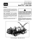
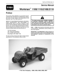
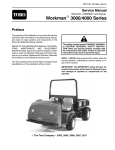
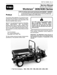
1
Part No. 08160SL (Rev. B)
Service Manual
WorkmanR MD & MDX
Preface
The purpose of this publication is to provide the service
technician with information for troubleshooting, testing
and repair of major systems and components on the
Workman MD and Workman MDX.
REFER TO THE OPERATOR’S MANUAL FOR OPERATING, MAINTENANCE AND ADJUSTMENT INSTRUCTIONS. For reference, insert a copy of the
Operator’s Manual and Parts Catalog for your machine
into Chapter 2 of this service manual. Additional copies
of the Operator’s Manual and Parts Catalog are available on the internet at www.Toro.com.
The Toro Company reserves the right to change product
specifications or this publication without notice.
This safety symbol means DANGER, WARNING,
or CAUTION, PERSONAL SAFETY INSTRUCTION. When you see this symbol, carefully read
the instructions that follow. Failure to obey the
instructions may result in personal injury.
NOTE: A NOTE will give general information about the
correct operation, maintenance, service, testing or repair of the machine.
IMPORTANT: The IMPORTANT notice will give important instructions which must be followed to prevent damage to systems or components on the
machine.
E The Toro Company - 2008, 2011, 2014
This page is intentionally blank.
Workman MD/MDX
Chapter 2 -- Product Records and Maintenance
Product Records . . . . . . . . . . . . . . . . . . . . . . . . . . .
Maintenance . . . . . . . . . . . . . . . . . . . . . . . . . . . . . . .
Equivalents and Conversions . . . . . . . . . . . . . . . .
Torque Specifications . . . . . . . . . . . . . . . . . . . . . . .
2 -2 -2 -2 --
1
1
2
3
Chapter 3 -- Briggs & Stratton Gasoline Engine
General Information . . . . . . . . . . . . . . . . . . . . . . . . 3 -- 2
Specifications . . . . . . . . . . . . . . . . . . . . . . . . . . . . . . 3 -- 3
Adjustments . . . . . . . . . . . . . . . . . . . . . . . . . . . . . . . 3 -- 4
Service and Repairs . . . . . . . . . . . . . . . . . . . . . . . . 3 -- 5
Briggs and Stratton Repair Manual for 4--Cycle, V--Twin
Cylinder, OHV Head Engines
Chapter 6 -- Electrical System
General Information . . . . . . . . . . . . . . . . . . . . . . . . 6 -- 2
Electrical Schematics . . . . . . . . . . . . . . . . . . . . . . . 6 -- 2
Special Tools . . . . . . . . . . . . . . . . . . . . . . . . . . . . . . 6 -- 3
Troubleshooting . . . . . . . . . . . . . . . . . . . . . . . . . . . . 6 -- 5
Electrical System Quick Checks . . . . . . . . . . . . . . 6 -- 7
Component Testing . . . . . . . . . . . . . . . . . . . . . . . . . 6 -- 8
Service and Repairs . . . . . . . . . . . . . . . . . . . . . . . 6 -- 18
ADVANCED MOTORS & DRIVES STARTER/
GENERATOR TROUBLESHOOTING GUIDE
Chapter 7 -- Chassis
Chapter 4 -- Single Cylinder Gasoline Engine
General Information . . . . . . . . . . . . . . . . . . . . . . . . 4 -- 2
Specifications . . . . . . . . . . . . . . . . . . . . . . . . . . . . . . 4 -- 3
Adjustments . . . . . . . . . . . . . . . . . . . . . . . . . . . . . . . 4 -- 4
Service and Repairs . . . . . . . . . . . . . . . . . . . . . . . . 4 -- 7
Kohler Service Manual for COMMAND PRO CS Series
Engines
General Information . . . . . . . . . . . . . . . . . . . . . . . .
Specifications . . . . . . . . . . . . . . . . . . . . . . . . . . . . . .
Special Tools . . . . . . . . . . . . . . . . . . . . . . . . . . . . . .
Troubleshooting . . . . . . . . . . . . . . . . . . . . . . . . . . . .
Adjustments . . . . . . . . . . . . . . . . . . . . . . . . . . . . . . .
Service and Repairs . . . . . . . . . . . . . . . . . . . . . . . .
7 -7 -7 -7 -7 -7 --
1
2
2
3
6
9
Chapter 8 -- Electrical Drawings
Electrical
Drawings
Chassis
Electrical
System
Electrical Schematics . . . . . . . . . . . . . . . . . . . . . . . 8 -- 3
Circuit Diagrams . . . . . . . . . . . . . . . . . . . . . . . . . . . 8 -- 5
Electrical Harness Drawings . . . . . . . . . . . . . . . . . 8 -- 7
Product Records
and Maintenance
General Information . . . . . . . . . . . . . . . . . . . . . . . . 5 -- 1
Specifications . . . . . . . . . . . . . . . . . . . . . . . . . . . . . . 5 -- 2
Drive Train Operation . . . . . . . . . . . . . . . . . . . . . . . 5 -- 3
Special Tools . . . . . . . . . . . . . . . . . . . . . . . . . . . . . . 5 -- 6
Adjustments . . . . . . . . . . . . . . . . . . . . . . . . . . . . . . . 5 -- 7
Service and Repairs . . . . . . . . . . . . . . . . . . . . . . . 5 -- 10
Briggs & Stratton
Gasoline Engine
Safety Instructions . . . . . . . . . . . . . . . . . . . . . . . . . . 1 -- 2
Jacking and Other Instructions . . . . . . . . . . . . . . . 1 -- 4
Safety and Instruction Decals . . . . . . . . . . . . . . . . 1 -- 6
Single Cylinder
Gasoline Engine
Chapter 5 -- Drive Train
Drive Train
Chapter 1 -- Safety
Safety
Table Of Contents
Workman MD/MDX
Rev. B
This page is intentionally blank.
Workman MD/MDX
Safety
Table of Contents
SAFETY INSTRUCTIONS . . . . . . . . . . . . . . . . . . . . . .
Supervisor’s Responsibilities . . . . . . . . . . . . . . . . .
Before Operating . . . . . . . . . . . . . . . . . . . . . . . . . . . .
While Operating . . . . . . . . . . . . . . . . . . . . . . . . . . . . .
Maintenance and Service . . . . . . . . . . . . . . . . . . . .
JACKING AND OTHER INSTRUCTIONS . . . . . . . . .
Jack Vehicle . . . . . . . . . . . . . . . . . . . . . . . . . . . . . . . .
Transport Vehicle . . . . . . . . . . . . . . . . . . . . . . . . . . .
Tow Vehicle . . . . . . . . . . . . . . . . . . . . . . . . . . . . . . . .
Transaxle Neutral Position . . . . . . . . . . . . . . . . . . . .
SAFETY AND INSTRUCTION DECALS . . . . . . . . . .
Workman MD/MDX
2
2
2
3
3
4
4
4
4
5
6
Page 1 -- 1
Safety
Safety
Chapter 1
Safety Instructions
The Workman MD and MDX series vehicles are designed and tested to offer safe service when operated
and maintained properly. Although hazard control and
accident prevention partially are dependent upon the
design and configuration of the machine, these factors
are also dependent upon the awareness, concern and
proper training of the personnel involved in the operation, transport, maintenance and storage of the machine. Improper use or maintenance of the machine can
result in injury or death.
Read and understand the contents of the Operator’s
Manual before starting and operating the machine. Become familiar with all controls and know how to stop it
quickly. Additional copies of the Operator’s Manual are
available on the internet at www.Toro.com.
The safety alert symbol means
CAUTION, WARNING or DANGER —
“personal safety instruction”. Read
and understand the instruction because it has to
do with safety. Failure to comply with the instruction may result in personal injury.
WARNING
To reduce the potential for injury or death, comply
with the following safety instructions.
WARNING
The Workman is an off--highway vehicle only. It is
not designed, equipped or manufactured for use
on public streets, roads or highways.
Supervisor’s Responsibilities
1. Make sure operators are thoroughly trained and familiar with the Operator’s Manual and all labels on the
vehicle.
2. Be sure to establish your own special procedures
and work rules for unusual operating conditions (e.g.
slopes too steep for vehicle operation).
Before Operating
1. Read and understand the contents of the Operator’s
Manual and Operator’s DVD before starting and operating the vehicle. Become familiar with the controls and
know how to stop the vehicle and engine quickly. Additional copies of the Operator’s Manual are available on
the internet at www.Toro.com.
3. Since fuel used in Workman vehicles is highly flammable, handle it carefully:
2. Keep all shields, safety devices and decals in place.
If a shield, safety device or decal is defective, illegible or
damaged, repair or replace it before operating the vehicle. Also, tighten any loose nuts, bolts or screws to ensure vehicle is in safe operating condition.
A. Store fuel in containers specifically designed for
this purpose.
B. Do not remove vehicle fuel tank cap while engine
is hot or running.
C. Do not smoke while handling fuel.
D. Fill fuel tank outdoors and only to within an inch of
the top of the tank, not the filler neck. Do not overfill
the fuel tank.
E. Clean up any spilled fuel.
Safety
Page 1 -- 2
Workman MD/MDX
1. Sit on the operator seat when starting and operating
the vehicle.
2. Before starting the engine:
A. Sit on operator’s seat and apply the parking
brake.
4. Do not touch engine, muffler or exhaust pipe while
engine is running or soon after it is stopped. These areas
could be hot enough to cause burns.
5. Before getting off the seat:
A. Stop movement of the vehicle.
B. Turn ignition key to ON.
B. Turn ignition key to OFF and wait for all movement to stop.
C. Depress accelerator pedal to start engine and engage drive system.
C. Remove key from ignition switch.
3. Do not run engine in a confined area without adequate ventilation. Exhaust fumes are hazardous and
could possibly be deadly.
D. Apply parking brake.
E. Do not park on slopes unless wheels are chocked
or blocked.
Maintenance and Service
1. Before servicing or making adjustments, turn all accessories off, release pressure from accelerator pedal,
allow engine to stop, set parking brake and remove key
from the ignition switch.
2. Make sure vehicle is in safe operating condition by
keeping all nuts, bolts and screws tight.
3. Never store the vehicle or fuel container inside
where there is an open flame, such as near a water heater or furnace.
4. If major repairs are ever needed or assistance is desired, contact an Authorized Toro Distributor.
5. To reduce potential fire hazard, keep engine area
free of excessive grease, grass, leaves and dirt.
6. If engine must be running to perform maintenance or
an adjustment, keep clothing, hands, feet and other
parts of the body away from moving parts. Keep bystanders away.
7. Do not overspeed the engine by changing governor
setting. To assure safety and accuracy, check maximum
engine speed.
8. Shut engine off before checking or adding oil to the
engine crankcase.
9. Disconnect battery before servicing the vehicle. Disconnect negative (--) battery cable first and positive (+)
cable last. If battery voltage is required for troubleshooting or test procedures, temporarily connect the battery.
Reconnect positive (+) cable first and negative (--) cable
last.
Workman MD/MDX
10.Battery acid is poisonous and can cause burns.
Avoid contact with skin, eyes and clothing. Protect your
face, eyes and clothing when working with a battery.
11. Battery gases can explode. Keep cigarettes, sparks
and flames away from the battery.
12.To assure optimum performance and continued
safety of the vehicle, use genuine Toro replacement
parts and accessories. Replacement parts and accessories made by other manufacturers may result in nonconformance with safety standards, and the warranty
may be voided.
13.When raising the vehicle to change tires or to perform other service, use correct blocks, hoists and jacks.
Make sure vehicle is parked on a solid level surface such
as a concrete floor. Prior to raising the vehicle, remove
any attachments that may interfere with the safe and
proper raising of the vehicle. Always chock or block
wheels. Use appropriate jack stands to support the
raised vehicle. If the vehicle is not properly supported by
jack stands, the vehicle may move or fall, which may result in personal injury (see Jacking Instructions in this
section).
14.Make sure to dispose of potentially harmful waste
(e.g. fuel, oil, engine coolant, filters, battery) in an environmentally safe manner. Follow all local codes and regulations when recycling or disposing of waste.
Page 1 -- 3
Rev. B
Safety
Safety
While Operating
Jacking and Other Instructions
Jack Vehicle
DANGER
POTENTIAL HAZARD
• A vehicle that is not properly supported
may become unstable.
WHAT CAN HAPPEN
• The vehicle may move or fall. Personal
injury or damage to the machine may result.
HOW TO AVOID THE HAZARD
• Make sure vehicle is parked on a solid level
surface, such as a concrete floor.
• Make sure engine is off and key is removed
from the ignition switch before getting off
the vehicle.
• Before raising the vehicle, remove any
attachments that may interfere with the safe
and proper raising of the vehicle.
• Always chock or block wheels to prevent
the vehicle from rolling.
• Do not start vehicle while it is on jack
stands without placing transaxle in neutral.
• Make sure proper hoists, jacks and jack
stands are used to raise and support the
vehicle.
2
1
Figure 1
1. Front frame
2. Towing tongue
1
2
Figure 2
Jacking Locations
1. Jack front of the vehicle on the front of the frame and
behind the towing tongue (Fig. 1).
1. Transaxle case
2. Axle tube
2. Jack rear of the vehicle under each rear axle tube. Do
not jack vehicle below the transaxle case (Fig. 2).
Transport Vehicle
When moving the vehicle long distances, use a trailer or
flatbed truck. Make sure vehicle is secured to the trailer
properly. Refer to Operator’s Manual for transport information.
Tow Vehicle
IMPORTANT: Frequent or long distance towing of
the Workman is not recommended.
In case of emergency, the vehicle can be towed for a
short distance. Refer to Operator’s Manual for towing
information.
Safety
IMPORTANT: If vehicle is towed, make sure that
ignition switch is in the OFF position and key is removed from switch.
Page 1 -- 4
Workman MD/MDX
When performing routine maintenance and/or engine
testing, the transaxle must be shifted into the neutral
position.
Safety
Transaxle Neutral Position
2
1. Park machine on a level surface, stop engine, set
parking brake and remove key from the ignition switch.
2. Move shift lever to the neutral position (Fig. 3).
1
3. Make sure transaxle is in the neutral position by rotating the driven clutch. The tires should not rotate. If tire
rotation does occur, see Adjust Shift Cables in the Adjustment section of Chapter 5 -- Drive Train.
3
Figure 3
1. Shift lever (in neutral)
2. Forward position
Workman MD/MDX
Page 1 -- 5
3. Reverse position
Safety
Safety and Instruction Decals
Numerous safety and instruction decals are affixed to
your Workman. If any decal becomes illegible or damaged, install a new decal. Part numbers are listed in the
Parts Catalog. Order replacement decals from your Authorized Toro Distributor.
Safety
Page 1 -- 6
Workman MD/MDX
Chapter 2
Product Records and Maintenance
PRODUCT RECORDS . . . . . . . . . . . . . . . . . . . . . . . . .
MAINTENANCE . . . . . . . . . . . . . . . . . . . . . . . . . . . . . . .
EQUIVALENTS AND CONVERSIONS . . . . . . . . . . .
Decimal and Millimeter Equivalents . . . . . . . . . . . .
U.S. to Metric Conversions . . . . . . . . . . . . . . . . . . .
TORQUE SPECIFICATIONS . . . . . . . . . . . . . . . . . . . .
Fastener Identification . . . . . . . . . . . . . . . . . . . . . . .
Standard Torque for Dry, Zinc Plated and
Steel Fasteners (Inch Series). . . . . . . . . . . . . . . .
Standard Torque for Dry, Zinc Plated and
Steel Fasteners (Metric Fasteners). . . . . . . . . . .
Other Torque Specifications . . . . . . . . . . . . . . . . . .
Conversion Factors . . . . . . . . . . . . . . . . . . . . . . . . . .
Product Records
and Maintenance
Table of Contents
1
1
2
2
2
3
3
4
5
6
6
Product Records
Insert Operator’s Manual and Parts Catalog for your
Workman at the end of this chapter. Additionally, if any
optional equipment or accessories have been installed
to your machine, insert the Installation Instructions, Operator’s Manuals and Parts Catalogs for those options
at the end of this chapter.
Maintenance
Maintenance procedures and recommended service intervals for your Workman are covered in the Operator’s
Manual. Refer to that publication when performing regular equipment maintenance.
Workman MD/MDX
Page 2 -- 1
Product Records and Maintenance
Equivalents and Conversions
0.09375
Product Records and Maintenance
Page 2 -- 2
Workman MD/MDX
Recommended fastener torque values are listed in the
following tables. For critical applications, as determined
by Toro, either the recommended torque or a torque that
is unique to the application is clearly identified and specified in this Service Manual.
These Torque Specifications for the installation and
tightening of fasteners shall apply to all fasteners which
do not have a specific requirement identified in this Service Manual. The following factors shall be considered
when applying torque: cleanliness of the fastener, use
of a thread sealant (e.g. Loctite), degree of lubrication
on the fastener, presence of a prevailing torque feature,
hardness of the surface underneath the fastener’s head
or similar condition which affects the installation.
As noted in the following tables, torque values should be
reduced by 25% for lubricated fasteners to achieve
the similar stress as a dry fastener. Torque values may
also have to be reduced when the fastener is threaded
into aluminum or brass. The specific torque value
should be determined based on the aluminum or brass
material strength, fastener size, length of thread engagement, etc.
The standard method of verifying torque shall be performed by marking a line on the fastener (head or nut)
and mating part, then back off fastener 1/4 of a turn.
Measure the torque required to tighten the fastener until
the lines match up.
Fastener Identification
Grade 1
Grade 5
Grade 8
Class 8.8
Inch Series Bolts and Screws
Metric Bolts and Screws
Figure 1
Workman MD/MDX
Class 10.9
Figure 2
Page 2 -- 3
Product Records and Maintenance
Product Records
and Maintenance
Torque Specifications
Standard Torque for Dry, Zinc Plated and Steel Fasteners (Inch Series)
Thread Size
# 6 -- 32 UNC
Grade 1, 5 &
8 with Thin
Height Nuts
SAE Grade 1 Bolts, Screws, Studs &
Sems with Regular Height Nuts
(SAE J995 Grade 2 or Stronger Nuts)
in--lb
in--lb
N--cm
10 + 2
13 + 2
147 + 23
# 6 -- 40 UNF
# 8 -- 32 UNC
13 + 2
25 + 5
282 + 30
# 8 -- 36 UNF
# 10 -- 24 UNC
18 + 2
30 + 5
339 + 56
# 10 -- 32 UNF
SAE Grade 5 Bolts, Screws, Studs &
Sems with Regular Height Nuts
(SAE J995 Grade 2 or Stronger Nuts)
SAE Grade 8 Bolts, Screws, Studs &
Sems with Regular Height Nuts
(SAE J995 Grade 5 or Stronger Nuts)
in--lb
N--cm
in--lb
N--cm
15 + 2
170 + 20
23 + 2
260 + 20
17 + 2
190 + 20
25 + 2
280 + 20
29 + 3
330 + 30
41 + 4
460 + 45
31 + 3
350 + 30
43 + 4
485 + 45
42 + 4
475 + 45
60 + 6
675 + 70
48 + 4
540 + 45
68 + 6
765 + 70
1/4 -- 20 UNC
48 + 7
53 + 7
599 + 79
100 + 10
1125 + 100
140 + 15
1580 + 170
1/4 -- 28 UNF
53 + 7
65 + 10
734 + 113
115 + 10
1300 + 100
160 + 15
1800 + 170
5/16 -- 18 UNC
115 + 15
105 + 17
1186 + 169
200 + 25
2250 + 280
300 + 30
3390 + 340
5/16 -- 24 UNF
138 + 17
128 + 17
1446 + 192
225 + 25
2540 + 280
325 + 30
3670 + 340
ft--lb
ft--lb
N--m
ft--lb
N--m
ft--lb
N--m
3/8 -- 16 UNC
16 + 2
16 + 2
22 + 3
30 + 3
41 + 4
43 + 4
58 + 5
3/8 -- 24 UNF
17 + 2
18 + 2
24 + 3
35 + 3
47 + 4
50 + 4
68 + 5
7/16 -- 14 UNC
27 + 3
27 + 3
37 + 4
50 + 5
68 + 7
70 + 7
95 + 9
7/16 -- 20 UNF
29 + 3
29 + 3
39 + 4
55 + 5
75 + 7
77 + 7
104 + 9
1/2 -- 13 UNC
30 + 3
48 + 7
65 + 9
75 + 8
102 + 11
105 + 10
142 + 14
1/2 -- 20 UNF
32 + 3
53 + 7
72 + 9
85 + 8
115 + 11
120 + 10
163 + 14
5/8 -- 11 UNC
65 + 10
88 + 12
119 + 16
150 + 15
203 + 20
210 + 20
285 + 27
5/8 -- 18 UNF
75 + 10
95 + 15
129 + 20
170 + 15
230 + 20
240 + 20
325 + 27
3/4 -- 10 UNC
93 + 12
140 + 20
190 + 27
265 + 25
359 + 34
375 + 35
508 + 47
3/4 -- 16 UNF
115 + 15
165 + 25
224 + 34
300 + 25
407 + 34
420 + 35
569 + 47
7/8 -- 9 UNC
140 + 20
225 + 25
305 + 34
430 + 45
583 + 61
600 + 60
813 + 81
7/8 -- 14 UNF
155 + 25
260 + 30
353 + 41
475 + 45
644 + 61
660 + 60
895 + 81
NOTE: Reduce torque values listed in the table above
by 25% for lubricated fasteners. Lubricated fasteners
are defined as threads coated with a lubricant such as
oil, graphite or thread sealant such as Loctite.
NOTE: Torque values may have to be reduced when
installing fasteners into threaded aluminum or brass.
The specific torque value should be determined based
on the fastener size, the aluminum or base material
strength, length of thread engagement, etc.
Product Records and Maintenance
NOTE: The nominal torque values listed above for
Grade 5 and 8 fasteners are based on 75% of the minimum proof load specified in SAE J429. The tolerance is
approximately + 10% of the nominal torque value. Thin
height nuts include jam nuts.
Page 2 -- 4
Workman MD/MDX
Standard Torque for Dry, Zinc Plated and Steel Fasteners (Metric Fasteners)
Class 8.8 Bolts, Screws and Studs with
Regular Height Nuts
(Class 8 or Stronger Nuts)
Class 10.9 Bolts, Screws and Studs with
Regular Height Nuts
(Class 10 or Stronger Nuts)
M5 X 0.8
57 + 5 in--lb
640 + 60 N--cm
78 + 7 in--lb
885 + 80 N--cm
M6 X 1.0
96 + 9 in--lb
1018 + 100 N--cm
133 + 13 in--lb
1500 + 150 N--cm
M8 X 1.25
19 + 2 ft--lb
26 + 3 N--m
27 + 2 ft--lb
36 + 3 N--m
M10 X 1.5
38 + 4 ft--lb
52 + 5 N--m
53 + 5 ft--lb
72 + 7 N--m
M12 X 1.75
66 + 7 ft--lb
90 + 10 N--m
92 + 9 ft--lb
125 + 12 N--m
M16 X 2.0
166 + 15 ft--lb
225 + 20 N--m
229 + 22 ft--lb
310 + 30 N--m
M20 X 2.5
325 + 33 ft--lb
440 + 45 N--m
450 + 37 ft--lb
610 + 50 N--m
NOTE: Reduce torque values listed in the table above
by 25% for lubricated fasteners. Lubricated fasteners
are defined as threads coated with a lubricant such as
oil, graphite or thread sealant such as Loctite.
NOTE: The nominal torque values listed above are
based on 75% of the minimum proof load specified in
SAE J1199. The tolerance is approximately + 10% of the
nominal torque value.
NOTE: Torque values may have to be reduced when
installing fasteners into threaded aluminum or brass.
The specific torque value should be determined based
on the fastener size, the aluminum or base material
strength, length of thread engagement, etc.
Workman MD/MDX
Page 2 -- 5
Product Records and Maintenance
Product Records
and Maintenance
Thread Size
Other Torque Specifications
SAE Grade 8 Steel Set Screws
Wheel Bolts and Lug Nuts
Thread Size
Recommended Torque
Thread Size
Square Head
Hex Socket
1/4 -- 20 UNC
140 + 20 in--lb
73 + 12 in--lb
5/16 -- 18 UNC
215 + 35 in--lb
145 + 20 in--lb
3/8 -- 16 UNC
35 + 10 ft--lb
18 + 3 ft--lb
1/2 -- 13 UNC
75 + 15 ft--lb
50 + 10 ft--lb
Recommended Torque**
7/16 -- 20 UNF
Grade 5
65 + 10 ft--lb
88 + 14 N--m
1/2 -- 20 UNF
Grade 5
80 + 10 ft--lb
108 + 14 N--m
M12 X 1.25
Class 8.8
80 + 10 ft--lb
108 + 14 N--m
M12 X 1.5
Class 8.8
80 + 10 ft--lb
108 + 14 N--m
** For steel wheels and non--lubricated fasteners.
Thread Cutting Screws
(Zinc Plated Steel)
Type 1, Type 23 or Type F
Thread Size
Baseline Torque*
No. 6 -- 32 UNC
20 + 5 in--lb
No. 8 -- 32 UNC
Thread Cutting Screws
(Zinc Plated Steel)
Thread
Size
Threads per Inch
Baseline Torque*
Type A
Type B
No. 6
18
20
20 + 5 in--lb
30 + 5 in--lb
No. 8
15
18
30 + 5 in--lb
No. 10 -- 24 UNC
38 + 7 in--lb
No. 10
12
16
38 + 7 in--lb
1/4 -- 20 UNC
85 + 15 in--lb
No. 12
11
14
85 + 15 in--lb
5/16 -- 18 UNC
110 + 20 in--lb
3/8 -- 16 UNC
200 + 100 in--lb
* Hole size, material strength, material thickness and finish must be considered when determining specific
torque values. All torque values are based on non--lubricated fasteners.
Conversion Factors
in--lb X 11.2985 = N--cm
ft--lb X 1.3558 = N--m
Product Records and Maintenance
N--cm X 0.08851 = in--lb
N--m X 0.7376 = ft--lb
Page 2 -- 6
Workman MD/MDX
Chapter 3
Briggs & Stratton Gasoline Engine
Table of Contents
Workman MDX
Page 3 -- 1 Rev. B
Briggs & Stratton
Gasoline Engine
GENERAL INFORMATION . . . . . . . . . . . . . . . . . . . . . 2
Operator’s Manual . . . . . . . . . . . . . . . . . . . . . . . . . . 2
SPECIFICATIONS . . . . . . . . . . . . . . . . . . . . . . . . . . . . 3
ADJUSTMENTS . . . . . . . . . . . . . . . . . . . . . . . . . . . . . . 4
Adjust Throttle Cable . . . . . . . . . . . . . . . . . . . . . . . . 4
SERVICE AND REPAIRS . . . . . . . . . . . . . . . . . . . . . . 5
Cooling System . . . . . . . . . . . . . . . . . . . . . . . . . . . . . 5
Air Cleaner . . . . . . . . . . . . . . . . . . . . . . . . . . . . . . . . . 6
Exhaust System . . . . . . . . . . . . . . . . . . . . . . . . . . . . 8
Fuel Tank . . . . . . . . . . . . . . . . . . . . . . . . . . . . . . . . . 10
Oil Filter Assembly . . . . . . . . . . . . . . . . . . . . . . . . . 12
Engine . . . . . . . . . . . . . . . . . . . . . . . . . . . . . . . . . . . . 14
Engine Removal . . . . . . . . . . . . . . . . . . . . . . . . . . 15
Engine Installation . . . . . . . . . . . . . . . . . . . . . . . . 16
Fuel Evaporative Control System (Serial Number
Above 310000000) . . . . . . . . . . . . . . . . . . . . . . . 18
BRIGGS & STRATTON REPAIR MANUAL FOR
4--CYCLE, V--TWIN CYLINDER, OHV HEAD ENGINES
Briggs & Stratton Gasoline Engine
General Information
This Chapter gives information about specifications,
maintenance, troubleshooting, testing and repair of the
V--twin cylinder, gasoline engine used in the Workman
MDX.
gines. The use of some specialized test equipment is explained. However, the cost of the test equipment and the
specialized nature of some repairs may dictate that the
work be done at an engine repair facility.
Most repairs and adjustments require tools which are
commonly available in many service shops. Special
tools are described in the Briggs & Stratton Repair
Manual for 4--Cycle, V--Twin Cylinder, OHV Head En-
Service and repair parts for Briggs & Stratton engines
are supplied through your local Toro distributor. If no
parts list is available, be sure to provide your distributor
with the Toro model and serial number.
Operator’s Manual
The Operator’s Manual provides information regarding
the operation, general maintenance and maintenance
intervals for your Workman MDX vehicle. Refer to the
Operator’s Manual for additional information when servicing the machine.
Briggs & Stratton Gasoline Engine
Page 3 -- 2
Workman MDX
Specifications
Item
Description
Make / Designation
Briggs and Stratton, 4--cycle, V--Twin Cylinder,
OHV, Air Cooled, Gasoline Engine -- Model 303440
Bore x Stroke
2.68” x 2.60” (68 mm x 66 mm)
29.3 in3 (480 cc)
Total Displacement
Mechanical Governor
Carburetor
Float Feed, Single Barrel
Fuel Pump
Pulsating Crankcase Vacuum
Fuel
Unleaded, regular grade gasoline
Fuel Tank Capacity
7.0 U.S. gal (26.5 l)
Lubrication System
Pressure Lubrication, Gear Driven Geroter Oil Pump
Crankcase Oil Capacity
1.75 U.S. qt (1.66 l) with new filter
Engine Oil
See Operator’s Manual
Ignition System
Flywheel magneto, twin electronic armatures
Spark Plugs
Champion RC 12YC (or equivalent)
Spark Plug Gap
0.030” (0.76 mm)
Starter/Generator
10.5 VDC 100 Amps/14 VDC and 23 Amps
Dry Weight (approximate)
Workman MDX
72 lb (32.4 kg)
Page 3 -- 3
Briggs & Stratton Gasoline Engine
Briggs & Stratton
Gasoline Engine
Governor
Adjustments
Adjust Throttle Cable
NOTE: The Workman MDX is equipped with an engine
governor. Refer to the Briggs & Stratton Repair Manual
at the end of this chapter for governor information on
these machines.
2
Depressing the accelerator pedal rotates the engine
governor bellcrank which tensions the main governor
spring to increase engine speed. Releasing the accelerator pedal decreases governor spring tension to reduce
engine speed.
1. Park machine on a level surface, stop engine, engage parking brake and remove key from the ignition
switch.
2. Lift cargo box and prop with rod to gain access to the
engine.
3. When the accelerator pedal is fully depressed the
engine governor bellcrank mechanism should have a
gap from 0.030” to 0.080” (0.8 to 2.0 mm) (Fig. 2). If
necessary, adjust jam nuts on throttle cable so that gap
is correct.
1
ACCELERATOR
PEDAL RELEASED
Figure 1
1. Throttle cable
2. Governor bellcrank
2
4. Make sure that shift lever is in the neutral position to
prevent the machine from moving.
3
5. With ignition switch in the RUN position, depress accelerator pedal and allow engine to start. Fully depress
accelerator pedal and have a second person measure
engine speed with a tachometer. With pedal fully depressed, engine speed should be from 3250 to 3350
RPM. If necessary, adjust throttle cable or engine governor so that engine speed is correct when the accelerator pedal is fully depressed.
6. After throttle cable adjustment is correct, lower and
secure cargo box.
Briggs & Stratton Gasoline Engine
1
ACCELERATOR
PEDAL DEPRESSED
Figure 2
1. Throttle cable
2. Governor bellcrank
Page 3 -- 4
Rev. B
3. Gap
Workman MDX
Service and Repairs
Cooling System
To ensure proper engine cooling, make sure the grass
screen, cooling fins and other external surfaces of the
engine are kept clean at all times.
NOTE: Perform this maintenance procedure at the interval specified in the Operator’s Manual.
1
IMPORTANT: The engine that powers the Workman
MDX is air--cooled. Operating the engine with dirty
or plugged cooling fins or a plugged or dirty blower
housing will result in engine overheating and damage.
1. Park machine on a level surface, stop engine, engage parking brake and remove key from the ignition
switch.
2. Raise cargo box and support with prop rod.
Figure 3
1. Cylinder head cooling fins
3. Carefully remove spark plug wires from the spark
plugs to prevent the engine from starting unexpectedly.
1
IMPORTANT: Never clean engine with pressurized
water. Water could enter and contaminate the fuel
system.
4. Clean cooling fins on both cylinder heads (Fig. 3).
5. Clean rotating screen and blower housing of dirt and
debris.
2
6. If necessary remove rotating screen and blower
housing from engine for more thorough engine cleaning.
IMPORTANT: Never operate engine without the rotating screen and blower housing installed. Overheating and engine damage will result.
Figure 4
1. Rotating screen
2. Blower housing
7. Make sure rotating screen and blower housing are
properly installed to the engine if removed.
8. Attach spark plug wires to spark plugs.
9. Lower and secure cargo box.
Workman MDX
Page 3 -- 5
Briggs & Stratton Gasoline Engine
Briggs & Stratton
Gasoline Engine
1
Air Cleaner
5
4
6
7
8
1
60 to 65 in--lb
(6.8 to 7.3 N--m)
9
3
10
2
11
12
19
13
17
12
14
15
18
16
17
RIGHT
FRONT
Figure 5
1.
2.
3.
4.
5.
6.
Air cleaner assembly
Bolt
Compression spring
Mounting band
Nut
Flange nut (2 used)
Briggs & Stratton Gasoline Engine
7.
8.
9.
10.
11.
12.
Cap screw (2 used)
Air cleaner bracket
Flange head screw (4 used)
Carburetor gasket (2 used)
Carburetor adapter
Hose clamp
Page 3 -- 6
13.
14.
15.
16.
17.
18.
Breather hose
Adapter gasket
Hose clamp
Intake hose
Hose clamp
Intake hose
Workman MDX
Removal (Fig. 5)
2
1. Make sure machine is parked on a level surface with
the engine OFF.
2. Raise cargo box and support with prop rod.
3
3. Thoroughly clean junction of intake hose and carburetor adapter on engine and air cleaner assembly.
4. Remove air cleaner components as needed using
Figure 5 as a guide. Discard any removed gaskets and
clean gasket mating surfaces.
4
1
Installation (Fig. 5)
Figure 6
1. Air cleaner
2. Carburetor adapter
3. Breather hose
4. Intake hose
1. Assemble all removed air cleaner components using
Figure 5 as a guide.
A. Install new gaskets (items 10 and 14) if they were
removed.
B. If flange head screws (item 9) were loosened or
removed, torque screws from 60 to 65 in--lb (6.8 to
7.3 N--m).
C. Make sure that air cleaner vacuator valve is
pointed toward ground and slightly toward engine after assembly.
D. Make sure to secure intake hoses with hose
clamps.
2. Lower and secure cargo box.
Workman MDX
Page 3 -- 7
Briggs & Stratton Gasoline Engine
Briggs & Stratton
Gasoline Engine
IMPORTANT: Any leaks in the air filter system will
allow dirt into engine and will cause serious engine
damage. Make sure that all air cleaner components
are in good condition and are properly secured during assembly.
Exhaust System
RIGHT
FRONT
9
4
10
1
2
7
6
5
4
3
8
Figure 7
1.
2.
3.
4.
Muffler
Swing arm
Cap screw (2 used)
Lock washer (6 used)
Briggs & Stratton Gasoline Engine
5. Exhaust coupler
6. Coupler spring (4 used)
7. Exhaust manifold
Page 3 -- 8
8. Engine tray
9. Engine
10. Screw (4 used)
Workman MDX
Removal (Fig. 7)
Installation (Fig. 7)
1. Park machine on a level surface, stop the engine, engage parking brake and remove the key from the ignition
switch.
NOTE: Mount all exhaust components loosely before
tightening to ensure a proper fit of exhaust system.
CAUTION
The muffler and exhaust pipe may be hot. To
avoid possible burns, allow engine and exhaust
system to cool before working on the muffler.
3. Remove four (4) coupler springs securing the exhaust coupler to the muffler and exhaust manifold. Remove exhaust coupler.
4. Remove two (2) cap screws and lock washers securing the muffler to the swing arm. Remove muffler from
machine.
5. If exhaust manifold needs to be removed from engine, remove four (4) screws and lock washers securing
the manifold to the engine. Remove exhaust manifold.
Remove exhaust gaskets and clean gasket surfaces of
manifold and engine.
Workman MDX
1. If the exhaust manifold was removed from engine,
install manifold to engine with new gaskets. Make sure
that gaskets align with exhaust ports of cylinder heads.
Loosely attach exhaust manifold to the engine with removed fasteners.
2. Position muffler to the machine. Secure muffler
loosely to the swing arm with two (2) cap screws and
lock washers.
3. Position exhaust coupler to the muffler and exhaust
manifold. Secure coupler with four (4) coupler springs.
4. Tighten screws that secure exhaust manifold to the
engine.
5. Tighten cap screws that secure muffler to the swing
arm.
6. Lower and secure cargo box.
Page 3 -- 9
Briggs & Stratton Gasoline Engine
Briggs & Stratton
Gasoline Engine
2. Raise cargo box and support with prop rod.
Fuel Tank
RIGHT
FRONT
1
15
16
11
10
2
3
9
8
7
12
5
6
13
4
14
13
1.
2.
3.
4.
5.
6.
Seat
Fuel gauge
Bushing
Gas cap
Fuel tank
Bushing
Briggs & Stratton Gasoline Engine
7.
8.
9.
10.
11.
Figure 8
Stand pipe
Hose clamp
Fuel hose (to fuel filter)
Fuel line conduit
Seat base
Page 3 -- 10
12.
13.
14.
15.
16.
Web strapping
Hex head flange screw (8 used)
Flat washer
Parking brake support
Shift bracket
Workman MDX
Fuel Tank Removal (Fig. 10)
4
CAUTION
2
5
Read safety precautions for handling gasoline
before working on the fuel system (see Safety Instructions in Chapter 1 -- Safety).
1
1. Remove seat base from the frame (see Seat Base
Removal in the Service and Repairs section of Chapter
7 -- Chassis).
3
2. Use fuel transfer pump to remove gas from fuel tank.
Figure 9
1. Shift lever
2. Cap screw (short)
3. Shift plate
4. Release tank strap that secures fuel tank to frame.
Do not remove strap from floor plate and frame cross
member. Lift tank from frame.
4. Cap screw (long)
5. Choke cable
Briggs & Stratton
Gasoline Engine
3. Loosen hose clamp and disconnect fuel hose from
the fuel tank stand pipe.
1
NOTE: Workman MDX vehicles with serial number
above 310000000 are equipped with a fuel evaporative
control system (EVAP) designed to collect and store
evaporative emissions from the fuel tank. Fuel tank
components for these vehicles are shown in Fig. 11.
2
5. If necessary, remove stand pipe, fuel gauge and
bushings from tank.
3
Fuel Tank Installation (Fig. 10)
1. If removed, install bushings, stand pipe and fuel
gauge to tank.
Figure 10
1. Fuel hose
2. Fuel tank
3. Tank strap
2. Position fuel tank to frame. Secure tank to frame and
cross member with tank strap.
8
7
3. Connect fuel hose to the tank stand pipe and secure
with hose clamp.
9
4
3
4. Install seat base to the frame (see Seat Base Installation in the Service and Repairs section of Chapter 7 -Chassis).
4
2
5
5. Fill fuel tank.
6
1
Figure 11
1.
2.
3.
4.
5.
Workman MDX
Page 3 -- 11
Fuel tank
Carbon canister
Rollover valve
Fuel hose (tank vent)
Fuel hose
Rev. B
6.
7.
8.
9.
Fresh air filter
Fuel hose (purge hose)
Check valve
Fuel hose (to engine)
Briggs & Stratton Gasoline Engine
Oil Filter Assembly
1
1
2
40 to 50 in--lb
(4.6 to 5.6 N--m)
40 to 50 in--lb
(4.6 to 5.6 N--m)
3
4
3
4
5
12
6
11
8
7
10
8
9
7
RIGHT
FRONT
Figure 11
1.
2.
3.
4.
Hose
Elbow fitting
Hose
Fitting
Briggs & Stratton Gasoline Engine
5.
6.
7.
8.
Oil pressure switch
Elbow fitting
Cap screw (4 used)
Flange nut (4 used)
Page 3 -- 12
9.
10.
11.
12.
Filter bracket
Oil filter
Oil filter adapter
Fitting
Workman MDX
Removal (Fig. 11)
Installation (Fig. 11)
1. Park machine on a level surface, stop the engine, engage parking brake and remove the key from the ignition
switch.
1. Install removed oil filter adapter components using
Figure 11 as a guide. Torque fittings (items 2, 4 and 6)
from 40 to 50 in--lb (4.6 to 5.6 N--m).
2. Raise cargo box and support with prop rod.
2. Check and adjust engine oil level.
3. To prevent contamination of engine lubrication system during adapter removal, thoroughly clean exterior of
filter adapter, hoses and fittings.
3. Lower and secure cargo box.
Briggs & Stratton
Gasoline Engine
4. Remove oil filter adapter components as needed using Figure 11 as a guide.
Workman MDX
Page 3 -- 13
Briggs & Stratton Gasoline Engine
Engine
5
4
6
41
40
RIGHT
30
FRONT
3
65 to 85 ft--lb
(88 to 115 N--m)
39
8
33
8
9
22
38
31
28
10
13
1
37
42
Loctite #242
1
36
1
43
2 17
25
27
19
11
29
20
14
12
24
15
16
18
29
35
7
Loctite #242
23
34
21
26
44
25 to 30 ft--lb
(34 to 40 N--m)
32
Figure 12
1.
2.
3.
4.
5.
6.
7.
8.
9.
10.
11.
12.
13.
14.
15.
Hose clamp
Fuel hose (from tank)
Cable bracket
Cable clamp
Cap screw
Threaded insert
Swing arm
Lock washer (6 used)
Cap screw (2 used)
Woodruff key
Lock washer
Nut
Starter V--belt
Cap screw (4 used)
Lock washer (4 used)
Briggs & Stratton Gasoline Engine
16.
17.
18.
19.
20.
21.
22.
23.
24.
25.
26.
27.
28.
29.
30.
Engine pulley
Negative cable
Starter spacer
Drive clutch
Washer
Cap screw
Flange nut (4 used)
Cap screw
Carriage screw
Engine tray
Washer (2 used)
Starter/generator pulley
Starter/generator
Flange nut (3 used)
Engine
Page 3 -- 14
31. Engine wire harness
32. Cap screw (2 used)
33. Screw (4 used)
34. Mount (2 used)
35. Cap screw (4 used)
36. Fuel filter
37. Fuel hose
38. Lock nut
39. Cable bracket
40. Ball stud
41. Cable
42. Exhaust manifold
43. Coupler spring (4 used)
44. Plastic cap
Workman MDX
Engine Removal (Fig. 12)
1. Park machine on a level surface, stop engine, engage parking brake and remove key from the ignition
switch.
2. Disconnect negative (black) cable from the battery.
Then, disconnect positive (red) cable from the battery.
3
3. Remove cargo box to gain access to the engine (see
Cargo Box and Tailgate Removal in the Service and Repairs section of Chapter 7 -- Chassis).
4. Depending on needed engine repairs, it may be easier to drain engine oil from engine before engine removal.
1
5
Figure 13
1. Throttle cable
2. Choke cable
3. Cable bracket
4. Air intake hose
5. Fuel inlet hose
6
5. Disconnect the following components (Fig. 13):
A. Choke and throttle cables from the carburetor
and cable brackets.
5
3
4
B. Air intake hose from the air cleaner intake and
machine frame.
CAUTION
1
2
Read safety precautions for handling gasoline
before working on the fuel system (see Safety Instructions in Chapter 1 -- Safety).
6. Disconnect fuel inlet hose from the fuel pump (Fig.
13).
Figure 14
1. Choke cable
2. Throttle cable
3. Carburetor
4. Fuel hose
5. Air intake hose
6. Breather hose
7. Remove muffler and exhaust coupler from the machine (see Exhaust System Removal in this section).
8. Remove drive belt from drive clutch.
9. Loosen fasteners that secure starter/generator. Rotate starter/generator to loosen tension on starter belt
and remove belt from the engine and starter/generator
pulleys.
10.Remove two (2) cap screws and flange nuts that secure oil filter adapter to filter bracket (Fig. 16). Carefully
place filter and adapter to allow them to be removed with
engine.
2
1
Figure 15
1. Starter/Generator ground cable to engine
2. Starter/Generator terminal (A1)
Workman MDX
Page 3 -- 15
Briggs & Stratton Gasoline Engine
Briggs & Stratton
Gasoline Engine
IMPORTANT: To prevent contaminants from entering the engine and fuel system, make sure all hoses
and engine openings are covered or plugged after
disconnecting.
2
4
11. Disconnect electrical connections from the following
engine components:
6
A. Disconnect ground cable to engine at starter/
generator terminal A1 (Fig. 15).
B. Disconnect engine harness connector from the
main harness.
1
12.Remove four (4) flange nuts and cap screws securing the engine to the engine tray.
2
5
4
3
CAUTION
One person should operate the hoist while the
other person guides the engine out of the frame.
13.Remove engine from the engine tray.
A. Attach a short section of chain between both engine lift tabs.
B. Connect hoist to center of chain.
IMPORTANT: Make sure to not damage the engine, fuel hoses, electrical harness or other parts
while removing the engine.
C. Slowly remove engine from the machine.
14.Remove engine parts and attachments as necessary to repair the engine.
Figure 16
1. Oil filter adapter
2. Oil filter
3. Filter bracket
4. Cap screw
5. Flange nut
6. Engine
3. Install four (4) cap screws and flange nuts to engine
and engine tray. Position engine on engine tray to align
clutch drive pulley and driven pulley on transaxle. Tighten fasteners.
4. Carefully position oil filter assembly to filter bracket
(Fig. 16). Secure filter adapter with two (2) cap screws
and flange nuts.
5. Connect the following electrical components:
Engine Installation (Fig. 12)
A. Connect ground cable from the engine at starter/
generator terminal A1 (Fig. 15).
1. Install all removed parts and attachments to the engine.
B. Connect engine harness connector to the main
harness connector.
6. Install starter belt to the engine and starter/generator
pulleys. Tension the belt by rotating the starter/generator away from the engine. Tighten fasteners to secure
starter/generator.
CAUTION
One person should operate the hoist while the
other person guides the engine into the frame.
2. Install engine to the engine tray.
A. Attach a short section of chain between both engine lift tabs.
B. Connect a hoist at the center of the short section
of chain.
7. Install drive belt to drive clutch.
IMPORTANT: Make sure to remove all plugs and
covers that were placed on hose and engine openings during engine removal.
8. Install muffler and exhaust coupler to the machine
(see Exhaust System Installation in this section).
9. Connect fuel inlet hose to the fuel pump (Fig. 13).
IMPORTANT: Make sure to not damage engine,
fuel lines, electrical harness or other parts while
installing the engine.
C. Carefully lower engine onto the engine tray.
Briggs & Stratton Gasoline Engine
Page 3 -- 16
Workman MDX
10.Connect the following components (Fig. 13):
A. Choke and throttle cables to the carburetor and
cable bracket.
12.Connect positive (red) cable to the battery. Then,
connect negative (black) cable to the battery.
13.Make sure engine oil level is correct.
Briggs & Stratton
Gasoline Engine
B. Air intake hose to the air cleaner intake and machine frame.
11. Install cargo box to the frame (see Cargo Box and
Tailgate Installation in the Service and Repairs section
of Chapter 7 -- Chassis).
Workman MDX
Page 3 -- 17
Briggs & Stratton Gasoline Engine
Fuel Evaporative Control System (Serial Number Above 310000000)
ROLLOVER
VALVE
TO INTAKE
MANIFOLD
FUEL
TANK
CARBON
CANISTER
CHECK
VALVE
ENGINE
FRESH AIR
FILTER
Figure 18
Workman MDX vehicles with serial number above
310000000 are equipped with a fuel evaporative control
system (EVAP) designed to collect and store evaporative emissions from the fuel tank. The EVAP uses a carbon canister to collect these evaporative emissions.
Fuel vapors from the fuel tank are vented to the canister
where they are stored. Vapors from the canister are consumed when the engine is running which purges the
canister.
Machines with a carbon canister include a single engine
connection to the engine intake system that is used to
connect the evaporative system to the engine. These
machines use an inline check valve between the carbon
canister and the engine fitting. Evaporative control system components for Workman MDX vehicles are shown
in Figure 19.
The fuel tank on these Workman vehicles uses a non-vented fuel cap. To connect the tank to the evaporative
control system, a rollover valve is positioned in the top
of the tank that allows tank venting through the carbon
canister.
NOTE: If there is restriction in the fresh air filter, the carbon canister or the rollover valve, the fuel tank may distort due to venting issues. If the fuel tank returns to it’s
normal shape when the fuel cap is removed, restriction
in the evaporative control system is likely.
Briggs & Stratton Gasoline Engine
Page 3 -- 18
Rev. B
Workman MDX
Disassembly (Fig. 19)
8
DANGER
7
9
4
Gasoline is flammable. Use caution when storing
or handling it. Wipe up any spilled fuel before
starting the engine.
3
4
2
1. Inspect carbon cannister and attached hoses for
damage or obvious leaks. A damaged or leaking cannister should be replaced.
5
6
2. Remove components as needed using Figure 19 as
a guide.
B. If carbon canister is to be removed, note hose
positions on the canister for assembly purposes
(Fig. 21).
C. Note location of hose clamps for assembly purposes.
Figure 19
1.
2.
3.
4.
5.
Fuel tank
Carbon canister
Rollover valve
Fuel hose (tank vent)
Fuel hose
Assembly
1
1. Install all removed components using Figure 19 as a
guide.
6.
7.
8.
9.
Fresh air filter
Fuel hose (purge hose)
Check valve
Fuel hose (to engine)
2
3
4
A. If check valve (item 7 in Fig. 19) was removed,
make sure that directional arrow on valve body
points toward engine (Fig. 20).
B. Make sure that fuel hoses are not kinked after
installation. Also, secure hoses with hose clamps.
Figure 20
1. Check valve
2. Directional arrow
3. Fitting from canister
4. Fitting to engine
1
2
3
Figure 21
1. Top of carbon canister
2. Fitting to rollover valve
Workman MDX
Page 3 -- 19
Rev. B
3. Fitting to engine
Briggs & Stratton Gasoline Engine
Briggs & Stratton
Gasoline Engine
1
A. If check valve (item 8 in Fig. 19) is removed, note
direction of directional arrow on valve body for assembly purposes (Fig. 20).
This page is intentionally blank.
Briggs & Stratton Gasoline Engine
Page 3 -- 20
Workman MDX
Chapter 4
Single Cylinder Gasoline Engine
Table of Contents
Workman MD
Page 4 -- 1
Single Cylinder
Gasoline Engine
GENERAL INFORMATION . . . . . . . . . . . . . . . . . . . . . 2
Operator’s Manual . . . . . . . . . . . . . . . . . . . . . . . . . . 2
SPECIFICATIONS . . . . . . . . . . . . . . . . . . . . . . . . . . . . 3
ADJUSTMENTS . . . . . . . . . . . . . . . . . . . . . . . . . . . . . . 4
Adjust Throttle Cable (Serial Numbers Below
313000400) . . . . . . . . . . . . . . . . . . . . . . . . . . . . . . 4
Adjust Throttle Cable (Serial Numbers Above
313000400) . . . . . . . . . . . . . . . . . . . . . . . . . . . . . . 5
SERVICE AND REPAIRS . . . . . . . . . . . . . . . . . . . . . . 7
Cooling System . . . . . . . . . . . . . . . . . . . . . . . . . . . . . 7
Exhaust System . . . . . . . . . . . . . . . . . . . . . . . . . . . . 8
Fuel Tank . . . . . . . . . . . . . . . . . . . . . . . . . . . . . . . . . 10
Engine . . . . . . . . . . . . . . . . . . . . . . . . . . . . . . . . . . . . 12
Engine Removal . . . . . . . . . . . . . . . . . . . . . . . . . . 13
Engine Installation . . . . . . . . . . . . . . . . . . . . . . . . 14
Fuel Evaporative Control System (Serial Numbers
Above 311000000) . . . . . . . . . . . . . . . . . . . . . . . 16
KOHLER SERVICE MANUAL FOR COMMAND PRO
CS SERIES ENGINES
Rev. B
Single Cylinder Gasoline Engine
General Information
This Chapter gives information about specifications,
maintenance, troubleshooting, testing and repair of the
single cylinder gasoline engine used in the Workman
MD.
Workman MD vehicles with serial numbers below
311000000 have an engine that is identified as a Kohler
Command Pro CS engine. Workman MD vehicles with
serial numbers above 311000000 have an engine that
is identified as a Yamaha MZ360 engine. From a service
standpoint, these engines are essentially the same. The
Kohler Service Manual for COMMAND PRO CS Series
Engines is included at the end of this chapter and can be
used when servicing either brand of engine.
Most repairs and adjustments require tools which are
commonly available in many service shops. Special
tools are described in the Kohler Service Manual for
COMMAND PRO CS Series Engines and the use of
some specialized test equipment is explained. The cost
of the test equipment and the specialized nature of
some repairs may dictate that engine work be done at
an engine repair facility.
Service and repair parts for the engine used in the Workman MD can be provided by your local Toro distributor.
Operator’s Manual
The Operator’s Manual provides information regarding
the operation, general maintenance and maintenance
intervals for your Workman MD vehicle. Refer to the Operator’s Manual for additional information when servicing the machine.
Single Cylinder Gasoline Engine
Page 4 -- 2
Rev. A
Workman MD
Specifications
Item
Description
Make / Designation
4--cycle, Single Cylinder, OHV,
Air Cooled, Gasoline Engine
Bore x Stroke
3.35 in x 2.48 in (85 mm x 63 mm)
21.8 in3 (357 cc)
Total Displacement
Governor
Transaxle, Ground Speed Governing
Carburetor
Float Feed, Single Barrel
Fuel Pump
Pulsating Crankcase Vacuum
Fuel
Unleaded regular grade gasoline
Fuel Tank Capacity
7.0 U.S. gal (26.5 l)
Lubrication System
Splash Lubrication
1.2 U.S. qt (1.1 l)
Engine Oil
See Operator’s Manual
Spark Plugs
Champion RC 14YC (or equivalent)
Spark Plug Gap
0.030 in (0.76 mm)
Starter/Generator
10.5 VDC 100 Amps/14 VDC and 23 Amps
Dry Weight (approximate)
Workman MD
70.5 lb (31.9 kg)
Page 4 -- 3 Rev. A
Single Cylinder Gasoline Engine
Single Cylinder
Gasoline Engine
Crankcase Oil Capacity
Adjustments
Adjust Throttle Cable (Serial Numbers Below 313000400)
NOTE: Workman MD vehicles with serial numbers below 313000400 use a governor in the transaxle to control engine speed.
1
Releasing the accelerator pedal should allow the throttle
cable to close the carburetor throttle control lever so that
the lever touches the adjustment screw. The adjustment
screw keeps the throttle valve inside the carburetor
open slightly to prevent the valve from binding.
4
1. Park machine on a level surface, stop engine, engage parking brake and remove key from the ignition
switch.
3
2
2. Lift cargo box and prop with rod to gain access to the
engine and transaxle.
3. Rotate governor arm on transaxle fully clockwise
(Fig. 1).
Figure 1
4. Make sure of the following:
A. The carburetor throttle lever should be to the fully
open position without contacting the stop (Fig. 2).
1. Governor arm
2. Throttle cable
B. Adjust governor cable at the transaxle cable
bracket as necessary, so there is no compression of
the cable (Fig. 1). This will allow the throttle lever to
fully close when the accelerator pedal is released.
3. Governor cable
4. Cable bracket
1
5. Release the governor arm on transaxle and make
sure that the carburetor throttle lever fully closes.
3
6. After throttle cable adjustment is correct, lower and
secure cargo box.
2
Figure 2
1. Throttle cable
2. Governor cable
Single Cylinder Gasoline Engine
Page 4 -- 4
Rev. B
3. Carb throttle lever
Workman MD
Adjust Throttle Cable (Serial Numbers Above 313000400)
NOTE: Workman MD vehicles with serial numbers
above 313000400 use the engine governor to control
engine speed. Refer to the Kohler Service Manual at the
end of this chapter for governor information on these
machines.
Depressing the accelerator pedal rotates the engine
mounted throttle lever which tensions the engine governor spring to increase engine speed. Releasing the accelerator pedal decreases governor spring tension to
reduce engine speed.
2. Lift cargo box and prop with rod to gain access to the
engine (Fig. 3).
3. Make sure that shift lever is in the neutral position to
prevent the machine from moving.
5
1
2
Figure 3
1. Throttle cable
2. Throttle lever
3. Engine governor spring
4. Engine governor lever
5. Cable jam nut
Single Cylinder
Gasoline Engine
1. Park machine on a level surface, stop engine, engage parking brake and remove key from the ignition
switch.
4
3
NOTE: If phototac is to be used to measure engine
speed, DO NOT use driven clutch on transaxle for speed
measurement.
4. With ignition switch in the RUN position, depress accelerator pedal and allow engine to start. Fully depress
accelerator pedal and have a second person measure
engine speed with a tachometer. With pedal fully depressed, engine speed should be from 3250 to 3350
RPM. If necessary, adjust jam nuts on throttle cable so
that engine speed is correct when the accelerator pedal
is fully depressed.
5. After throttle cable adjustment is correct, lower and
secure cargo box.
Workman MD
Page 4 -- 5
Rev. B
Single Cylinder Gasoline Engine
This page is intentionally blank.
Single Cylinder Gasoline Engine
Page 4 -- 6
Workman MD
Service and Repairs
Cooling System
To ensure proper engine cooling, make sure the grass
screen, cooling fins and other external surfaces of the
engine are kept clean at all times.
1
NOTE: Perform this maintenance procedure at the interval specified in the Operator’s Manual.
IMPORTANT: The engine that powers the Workman
MD is air--cooled. Operating the engine with dirty or
plugged cooling fins or a plugged or dirty blower
housing will result in engine overheating and damage.
1. Park machine on a level surface, stop engine, engage parking brake and remove key from the ignition
switch.
2
Figure 4
1. Static debris screen
2. Blower housing
2. Raise bed and support with prop rod.
Single Cylinder
Gasoline Engine
3. Carefully remove spark plug wire from the spark plug
to prevent the engine from starting unexpectedly.
IMPORTANT: Never clean engine with pressurized
water. Water could enter and contaminate the fuel
system.
4. Clean cooling fins on cylinder head.
5. Clean static debris screen and blower housing of dirt
and debris. Remove screen and housing if necessary
(Fig. 4).
IMPORTANT: Never operate engine without the
blower housing installed. Overheating and engine
damage will result.
6. Make sure static screen and blower housing are reinstalled to the engine if removed.
7. Attach spark plug wire to spark plug.
8. Lower and secure bed.
Workman MD
Page 4 -- 7
Single Cylinder Gasoline Engine
Exhaust System
RIGHT
12
3
4
FRONT
5
2
1
6
7
8
9
10
11
Figure 5
1.
2.
3.
4.
Engine
Coupler spring (4 used)
Exhaust manifold
Muffler
Single Cylinder Gasoline Engine
5.
6.
7.
8.
Exhaust coupler
Starter/generator
Drive clutch
Engine tray
Page 4 -- 8
9.
10.
11.
12.
Lock washer (2 used)
Cap screw (2 used)
Swing arm
Nut (2 used)
Workman MD
Removal (Fig. 5)
3
1. Park machine on a level surface, stop the engine, engage parking brake and remove the key from the ignition
switch.
1
2. Raise cargo box and support with prop rod.
2
3
CAUTION
The muffler and exhaust pipe may be hot. To
avoid possible burns, allow engine and exhaust
system to cool before working on the muffler.
3. Remove four (4) springs securing the exhaust coupler to the muffler and exhaust manifold (Fig. 6).
Figure 6
1. Exhaust manifold
2. Exhaust coupler
3. Spring
4. Remove two (2) cap screws and lock washers securing the muffler to the swing arm.
5. Remove exhaust coupler and muffler.
Single Cylinder
Gasoline Engine
6. If needed, remove exhaust manifold from engine by
removing two (2) nuts. Remove exhaust gasket and
clean gasket surfaces of manifold and engine.
Installation (Fig. 5)
NOTE: Mount all exhaust components loosely before
tightening to ensure a proper fit of exhaust system.
1. If the exhaust manifold was removed from engine,
install manifold to engine with new gasket. Attach exhaust manifold loosely to the engine with removed nuts.
2. Install muffler to the swing arm with two (2) cap
screws and lock washers.
3. Insert exhaust coupler between muffler and manifold. Install springs to attach exhaust coupler to the exhaust manifold and muffler.
4. Tighten all exhaust system fasteners.
5. Lower and secure cargo box.
Workman MD
Page 4 -- 9
Single Cylinder Gasoline Engine
Fuel Tank
RIGHT
FRONT
1
15
16
11
10
2
3
9
8
7
5
6
12
13
4
14
13
1.
2.
3.
4.
5.
6.
Seat
Fuel gauge
Bushing
Gas cap
Fuel tank
Bushing
Single Cylinder Gasoline Engine
7.
8.
9.
10.
11.
Figure 7
Stand pipe
Hose clamp
Fuel hose (to fuel filter)
Fuel line conduit
Seat base
Page 4 -- 10
12.
13.
14.
15.
16.
Web strapping
Hex head flange screw (8 used)
Flat washer
Parking brake support
Shift bracket
Workman MD
Fuel Tank Removal (Fig. 7)
4
CAUTION
2
5
Read safety precautions for handling gasoline
before working on the fuel system (see Safety Instructions in Chapter 1 -- Safety).
1
1. Remove seat base from the frame (see Seat Base
Removal in the Service and Repairs section of Chapter
7 -- Chassis).
3
2. Use fuel transfer pump to remove gas from fuel tank.
Figure 8
4. Release tank web strapping from fuel tank. Do not remove strapping from floor plate and frame cross member. Lift tank from frame.
1
4. Cap screw (long)
5. Choke cable
NOTE: Workman MD vehicles with serial number
above 310000000 are equipped with a fuel evaporative
control system (EVAP) designed to collect and store
evaporative emissions from the fuel tank. Fuel tank
components for these vehicles are shown in Fig. 10.
2
5. If necessary, remove stand pipe, fuel gauge and
bushings from tank.
3
Fuel Tank Installation (Fig. 7)
Figure 9
1. If removed, install bushings, stand pipe and fuel
gauge to tank.
1. Fuel hose
2. Fuel tank
3. Tank web strapping
2. Position fuel tank to frame. Secure tank to frame and
cross member with tank web strapping.
8
7
3. Connect fuel hose to the tank stand pipe and secure
with hose clamp.
9
4
3
4. Install seat base to the frame (see Seat Base Installation in the Service and Repairs section of Chapter 7 -Chassis).
4
2
5
5. Fill fuel tank.
6
1
Figure 10
1.
2.
3.
4.
5.
Workman MD
Fuel tank
Carbon canister
Rollover valve
Fuel hose (tank vent)
Fuel hose
Page 4 -- 11 Rev. B
6.
7.
8.
9.
Fresh air filter
Fuel hose (purge hose)
Check valve
Fuel hose (to engine)
Single Cylinder Gasoline Engine
Single Cylinder
Gasoline Engine
3. Loosen hose clamp and disconnect fuel hose from
the fuel tank stand pipe.
1. Shift lever
2. Cap screw (short)
3. Shift plate
Engine
37
48
36
RIGHT
35
52
62
3
42
57
4
40
5
FRONT
18
Loctite #242
20
17
65 to 85 ft--lb
(88 to 115 N--m)
16
11
8
51
50
49
24
1
43
29
30
45
13
25
60
32
14
58
59
24
19
53
52
25 to 30 ft--lb
(34 to 40 N--m)
9
12
46
38
15
20
22
27
2
10
26
54
39
55
7
21
23
31
Loctite #242
61
28
42
47
40
56
27
41
Loctite #242
33
44
24
34
6
Figure 11
1.
2.
3.
4.
5.
6.
7.
8.
9.
10.
11.
12.
13.
14.
15.
16.
17.
18.
19.
20.
21.
Kohler engine
Coupler spring (4 used)
Exhaust manifold
Muffler
Exhaust coupler
Cap screw (2 used)
Drive clutch
Shift cable (2 used)
Starter belt
Cap screw
Fuel filter
Engine pulley spacer
Starter/generator
Starter pulley
Engine pulley
Hose clamp (3 used)
Fuel hose
Fuel hose conduit
Air filter mounting band
Engine wire harness
Engine tray
Single Cylinder Gasoline Engine
22.
23.
24.
25.
26.
27.
28.
29.
30.
31.
32.
33.
34.
35.
36.
37.
38.
39.
40.
41.
42.
Negative cable
Air cleaner bracket
Flange nut (7 used)
Carriage screw
Flange nut (2 used)
Hose clamp (2 used)
Hose clamp
Cap screw (4 used)
Lock washer (4 used)
Washer
Cap screw
Mount (2 used)
Washer (2 used)
Flywheel guard
Flat washer (4 used)
Flange head screw (4 used)
Intake hose
Cap screw (2 used)
Hose clamp (2 used)
Air cleaner assembly
Breather hose
Page 4 -- 12
43.
44.
45.
46.
47.
48.
49.
50.
51.
52.
53.
54.
55.
56.
57.
58.
59.
60.
61.
62.
Intake hose
Cap screw (4 used)
Fitting
Lock nut
Lock washer (2 used)
R--clamp
Cap screw
Flat washer
R--clamp
Cable tie (2 used)
Nut
Spring
Bolt
Cap screw (2 used)
Governor cable
Lock washer
Nut
Woodruff key
Plastic cap
Nut (2 used)
Workman MD
Engine Removal (Fig. 11)
1. Park machine on a level surface, stop engine, engage parking brake and remove key from the ignition
switch.
2. Disconnect ground (black) cable from the battery.
Then, disconnect positive (red) cable from the battery.
3. Remove cargo box to gain access to the engine (see
Cargo Box and Tailgate Removal in the Service and Repairs section of Chapter 7 -- Chassis).
IMPORTANT: Make sure all hoses and engine openings are plugged after disconnecting. This will prevent contaminants from entering the engine and
fuel system.
9. Remove cap screw (item 49) and flat washer (item
50) that secure r--clamp (item 51) and shift cables (item
8) to engine. Position shift cables away from engine.
10.Disconnect engine electrical harness connector
from the main harness.
11. Remove four (4) flange nuts and cap screws securing the engine to the engine tray.
CAUTION
One person should operate the hoist while a second person guides the engine out of the frame.
12.Remove engine from the engine tray.
A. Attach a short section of chain between fuel
pump bracket lift hole and exhaust manifold (Fig.
12).
A. Choke and governor cables from the carburetor
and cable bracket.
B. Air intake hose (item 38) from the carburetor.
B. Connect hoist to center of chain.
C. Breather hose (item 42) from the engine valve
cover.
IMPORTANT: Make sure to not damage the engine, fuel hoses, electrical harness or other parts
while removing the engine.
CAUTION
C. Slowly raise engine and attachments from the
machine.
Read safety precautions for handling gasoline
before working on the fuel system (see Safety Instructions in Chapter 1 -- Safety).
13.Remove engine parts and attachments as necessary to repair the engine.
5. Disconnect fuel hose from the fuel pump (Fig. 12).
Remove cable tie securing the choke and throttle cables
to the fuel pump bracket.
2
3
6
6. Remove muffler and exhaust coupler (see Muffler
Removal in this section).
4
5
7. Remove drive belt from drive clutch.
8. Loosen fasteners that secure starter/generator. Rotate starter/generator toward engine to loosen tension
on starter belt. Remove belt from the engine and starter/
generator pulleys.
1
7
Figure 12
1.
2.
3.
4.
Workman MD
Page 4 -- 13
Fuel pump bracket
Exhaust manifold
Fuel line
Drive belt
5. Starter/generator belt
6. Throttle cable
7. Governor cable
Single Cylinder Gasoline Engine
Single Cylinder
Gasoline Engine
4. Disconnect the following components:
Engine Installation (Fig. 11)
1. Install all removed engine parts and attachments to
the engine.
6. Install starter belt to the engine and starter/generator
pulleys. Tension the belt by rotating the starter/generator away from the engine. Tighten fasteners to secure
starter/generator.
7. Install drive belt to drive clutch.
CAUTION
One person should operate the hoist while a second person guides the engine into the frame.
2. Install engine to the frame.
A. Attach a short section of chain between fuel
pump bracket lift hole and exhaust manifold (Fig.
12).
IMPORTANT: Make sure to remove all plugs and
covers that were placed on hose and engine openings during engine removal.
8. Install muffler and exhaust coupler to the exhaust
manifold (see Muffler Installation in this section).
9. Connect fuel hose to the fuel pump (Fig. 12). Make
sure to secure hose with hose clamp.
10.Connect the following components:
B. Connect a hoist at the center of the chain.
A. Choke and throttle cables to the carburetor and
cable bracket.
IMPORTANT: Make sure to not damage engine,
fuel lines, electrical harness or other parts while
installing the engine.
B. Air intake hose to the carburetor.
C. Breather hose to the engine valve cover.
C. Lower engine onto the engine tray.
3. Install four (4) cap screws and flange nuts to engine
and engine tray. Position engine on engine tray to align
clutch drive pulley and driven pulley on transaxle. Tighten fasteners.
4. Connect engine harness connector to the main electrical harness.
5. Remove cap screw (item 49) and flat washer (item
50) that secure r--clamp (item 51) and shift cables (item
8) to engine. Position r--clamp (item 51) and shift cables
(item 8) to engine. Secure r--clamp to engine with flat
washer (item 50) and cap screw (item 49).
Single Cylinder Gasoline Engine
11. Secure choke and throttle cables to the fuel pump
bracket with cable tie.
12.Install cargo box to the frame (see Cargo Box and
Tailgate Installation in the Service and Repairs section
of Chapter 7 -- Chassis).
13.Connect positive (red) cable to the battery. Then,
connect ground (black) cable to the battery.
14.Make sure engine oil level is correct.
Page 4 -- 14
Workman MD
Single Cylinder
Gasoline Engine
This page is intentionally blank.
Workman MD
Page 4 -- 15
Single Cylinder Gasoline Engine
Fuel Evaporative Control System (Serial Number Above 310000000)
ROLLOVER
VALVE
FUEL
TANK
CARBON
CANISTER
CHECK
VALVE
ENGINE
FRESH AIR
FILTER
Figure 13
Workman MD vehicles with serial number above
310000000 are equipped with a fuel evaporative control
system (EVAP) designed to collect and store evaporative emissions from the fuel tank. The EVAP uses a carbon canister to collect these evaporative emissions.
Fuel vapors from the fuel tank are vented to the canister
where they are stored. Vapors from the canister are consumed when the engine is running which purges the
canister.
3
The fuel tank on these Workman vehicles uses a non-vented fuel cap. To connect the tank to the evaporative
control system, a rollover valve is positioned in the top
of the tank that allows tank venting through the carbon
canister.
NOTE: If there is restriction in the fresh air filter, the carbon canister or the rollover valve, the fuel tank may distort due to venting issues. If the fuel tank returns to it’s
normal shape when the fuel cap is removed, restriction
in the evaporative control system is likely.
1
2
Figure 14
1. Hose from check valve
2. Hose to air cleaner
3. Hose from engine
Machines with a carbon canister include a single engine
connection to the engine intake system that is used to
connect the evaporative system to the engine. These
machines use an inline check valve between the carbon
canister and the engine fitting. Evaporative control system components for Workman MD vehicles are shown
in Figure 15.
Single Cylinder Gasoline Engine
Page 4 -- 16
Rev. B
Workman MD
Disassembly
8
DANGER
7
9
4
Gasoline is flammable. Use caution when storing
or handling it. Wipe up any spilled fuel before
starting the engine.
3
4
2
1. Inspect carbon cannister and attached hoses for
damage or obvious leaks. A damaged or leaking cannister should be replaced.
5
6
2. Remove components as needed using Figure 15 as
a guide.
1
A. If check valve (item 8 in Fig. 15) is removed, note
direction of arrow on valve body for assembly purposes (Fig. 16).
Assembly
1. Install all removed components using Figure 15 as a
guide.
Figure 15
1.
2.
3.
4.
5.
Fuel tank
Carbon canister
Rollover valve
Fuel hose (tank vent)
Fuel hose
A. If check valve (item 8 in Fig. 15) was removed,
make sure that arrow on valve body points toward
engine.
1
6.
7.
8.
9.
Fresh air filter
Fuel hose (purge hose)
Check valve
Fuel hose (to engine)
2
3
4
B. Make sure that fuel hoses are not kinked after
installation. Also, secure hoses with hose clamps.
Figure 16
1. Check valve
2. Directional arrow
3. Fitting from canister
4. Fitting to engine
1
2
3
Figure 17
1. Top of carbon canister
2. Fitting to rollover valve
Workman MD
Page 4 -- 17 Rev. B
3. Fitting to engine
Single Cylinder Gasoline Engine
Single Cylinder
Gasoline Engine
B. Note location of hose clamps for assembly purposes.
This page is intentionally blank.
Single Cylinder Gasoline Engine
Page 4 -- 18
Workman MD
Chapter 5
Drive Train
Table of Contents
Driven Clutch . . . . . . . . . . . . . . . . . . . . . . . . . . . . . . 14
Driven Clutch Service (Serial Number
Below 310000000) . . . . . . . . . . . . . . . . . . . . . . . 15
Driven Clutch Service (Serial Number
Above 310000000) . . . . . . . . . . . . . . . . . . . . . . 15.1
Transaxle . . . . . . . . . . . . . . . . . . . . . . . . . . . . . . . . . 16
Removal . . . . . . . . . . . . . . . . . . . . . . . . . . . . . . . . 16
Installation . . . . . . . . . . . . . . . . . . . . . . . . . . . . . . . 18
Transaxle Service . . . . . . . . . . . . . . . . . . . . . . . . . . 20
Transaxle Disassembly and Inspection . . . . . . 21
Transaxle Assembly . . . . . . . . . . . . . . . . . . . . . . 35
Drive Train
GENERAL INFORMATION . . . . . . . . . . . . . . . . . . . . . 1
Operator’s Manual . . . . . . . . . . . . . . . . . . . . . . . . . . 1
SPECIFICATIONS . . . . . . . . . . . . . . . . . . . . . . . . . . . . 2
DRIVE TRAIN OPERATION . . . . . . . . . . . . . . . . . . . . 3
Clutch System Operation . . . . . . . . . . . . . . . . . . . . . 3
Drive Clutch Operation . . . . . . . . . . . . . . . . . . . . . . . 4
Driven Clutch Operation . . . . . . . . . . . . . . . . . . . . . 5
SPECIAL TOOLS . . . . . . . . . . . . . . . . . . . . . . . . . . . . . 6
ADJUSTMENTS . . . . . . . . . . . . . . . . . . . . . . . . . . . . . . 7
Adjust Ground Speed (Workman MD with
Serial Number Below 313000400) . . . . . . . . . . . 7
Adjust Ground Speed (Workman MDX and
Workman MD with Serial Number Above
313000400) . . . . . . . . . . . . . . . . . . . . . . . . . . . . . . 8
Adjust Shift Cables . . . . . . . . . . . . . . . . . . . . . . . . . . 9
SERVICE AND REPAIRS . . . . . . . . . . . . . . . . . . . . . 10
Drive Clutch . . . . . . . . . . . . . . . . . . . . . . . . . . . . . . . 10
Drive Clutch Service (Serial Number
Below 310000000) . . . . . . . . . . . . . . . . . . . . . . . 12
Drive Clutch Service (Serial Number
Above 310000000) . . . . . . . . . . . . . . . . . . . . . . 13.3
General Information
Operator’s Manual
The Operator’s Manual provides information regarding
the operation, general maintenance and maintenance
intervals for your Workman vehicle. Refer to the Operator’s Manual for additional information when servicing
the machine.
Workman MD/MDX
Page 5 -- 1 Rev. B
Drive Train
Specifications
Item
Description
Transaxle
Transaxle Fluid Capacity
Transaxle Fluid
1.5 quarts (1.4 liters)
SAE 10W--30 Motor Oil
Clutch System
Drive Clutch
Driven Clutch
Drive Train
Continuously variable transmission type, torque convertor
Speed sensing with mechanical fly weights
Torque sensing with spring loaded cam
Page 5 -- 2
Workman MD/MDX
Drive Train Operation
Clutch System Operation
1
3
A
B
4
6
C
7
5
Drive Train
9
v
8
2
Figure 1
1. Drive clutch (engine mounted)
2. Driven clutch (transaxle mounted)
3. Moveable sheave (drive clutch)
4. Fixed sheave (drive clutch)
5. Moveable sheave (driven clutch)
6. Button
Power is transferred from the engine to the transaxle by
a variable clutch system that consists of two clutches
connected by a drive belt. The drive clutch responds to
engine speed, and is mounted to the engine drive shaft.
The driven clutch responds to changes in load to the rear
axle, and is mounted to the transaxle input shaft.
Workman MD/MDX
7. Ramp (fixed cam)
8. Spring
9. Fixed sheave (driven clutch)
The two clutches work together to automatically up--shift
and back--shift as changes in load and speed occur. This
shifting changes the turning ratio between the drive and
driven clutches and allows the engine to operate at optimum efficiency.
Page 5 -- 3
Rev. A
Drive Train
Drive Clutch Operation
The operation of the drive clutch is affected by engine
shaft speed. When the engine is off and not turning, the
drive belt rests low within the drive clutch sheaves as the
clutch sheaves are spaced apart. As the engine is
started and increases in speed, the clutch weights move
outward as they spin about the engine drive shaft. The
outward movement of the weights against the spider assembly forces the moveable sheave closer to the fixed
sheave. This inward movement of the moveable sheave
engages the drive belt which begins to rotate.
1
2
3
4
With increasing engine speed, the moveable sheave
continues to move inward. This sheave movement
forces the drive belt to ride towards the outer diameter
of the drive clutch sheaves which increases the drive
belt speed.
When engine speed is decreased, the weights exert
less force on the moveable sheave. The reduced force
causes the moveable sheave to shift away from the fixed
sheave and slows the drive belt speed. As engine speed
continues to decrease, the drive belt disengages from
the clutch sheaves.
The drive clutch used on vehicles with serial numbers
below 310000000 (Fig. 2) includes three (3) rollers,
three (3) cam weights and a spring to control operation
of the moveable sheave.
6
5
7
Figure 2
1.
2.
3.
4.
Fixed sheave
Moveable sheave
Spider assembly
Cover
The drive clutch used on vehicles with serial numbers
above 310000000 (Fig. 3) controls moveable sheave
operation with six (6) weighted rollers and ramp surfaces in the moveable sheave.
5.
6.
7.
1
Spring
Cam weight (3 used)
Roller (3 used)
5
2
4
3
Figure 3
1.
2.
3.
Drive Train
Page 5 -- 4
Fixed sheave
Moveable sheave
Spider assembly
Rev. A
4.
5.
Cover
Roller (6 used)
Workman MD/MDX
Driven Clutch Operation
The operation of the driven clutch is affected by transaxle load. When the vehicle is stopped, the drive belt is
held at the outer diameter of the driven clutch sheaves
from the pressure of the spring pushing the moveable
sheave against the fixed sheave and away from the
fixed cam.
1
5
2
Once the drive belt starts rotating, the driven clutch also
starts to rotate. With increasing speed of the drive
clutch, the drive belt begins to climb to the outer diameter of the drive clutch sheaves. This increases the tension on the drive belt, and forces the moveable sheave
of the driven clutch to move away from the fixed sheave
against the pressure of the spring. As the belt tightens
and the sheaves open up, the drive belt rides lower in the
driven clutch sheaves.
With increased load to the transaxle, the fixed cam resists forward movement relative to the moveable
sheave and drive belt. Torque from the drive belt and
spring pressure moves the moveable sheave up the
ramp of the fixed cam. The drive belt becomes positioned closer to the outer diameter of the driven clutch
sheaves.
3
4
Figure 4
1. Moveable sheave
2. Ramp (fixed cam)
3. Button
On vehicles with a serial number below 310000000,
three (3) sets of buttons on the driven clutch moveable
sheave provide a low friction surface on which the moveable sheave can slide on the ramp of the fixed cam (Fig.
4).
4. Fixed sheave
5. Spring
2
Drive Train
3
On vehicles with a serial number above 310000000, a
fixed cam on the driven clutch moveable sheave rotates
on a pair of rollers in the fixed sheave base to allow low
friction movement of the moveable sheave (Fig. 5).
1
Figure 5
1. Moveable sheave
2. Fixed sheave
Workman MD/MDX
Page 5 -- 5
Rev. A
3. Spring
Drive Train
Special Tools
Order special tools from your Toro Distributor.
Drive Clutch Removal Tool (Serial Number Below 310000000)
This tool is required to remove the drive clutch from the
tapered drive shaft of the engine. It is placed in the
threaded hole of the fixed clutch sheave after the clutch
holding cap screw is removed.
Toro Part Number: TOR4094
NOTE: Vehicles with a serial number below 310000000
are equipped with a Comet brand drive clutch.
Figure 6
Drive Clutch Spider Removal Tool Kit (Serial Number Below 310000000)
This kit is required to remove the drive clutch spider from
the post of the fixed sheave. Kit includes spanner and
clutch holding bar.
4
1
23
Toro Part Number: TOR4098
NOTE: Vehicles with a serial number below 310000000
are equipped with a Comet brand drive clutch.
1
2
Figure 7
1. Holding bar
2. Spanner
Clutch Dry Lubricant (Serial Number Below 310000000)
This lubricant should be used to properly lubricate drive
clutch components on vehicles with serial numbers below 310000000.
Toro Part Number: 104--7011
NOTE: Vehicles with a serial number below 310000000
are equipped with a Comet brand drive clutch.
Figure 8
Drive Train
Page 5 -- 6
Rev. A
Workman MD/MDX
Drive Clutch Removal Tool (Serial Number Above 310000000)
This tool is required to remove the drive clutch from the
tapered drive shaft of the engine. It is placed in the
threaded hole of the fixed clutch sheave after the clutch
holding cap screw is removed.
Toro Part Number: TOR6013
NOTE: Vehicles with a serial number above
310000000 are equipped with a TEAM brand drive
clutch.
Figure 8.1
Drive Clutch Spider Removal Tool Kit (Serial Number Above 310000000)
This kit is required to remove the drive clutch spider from
the post of the fixed sheave. Kit includes spanner and
clutch holding bar.
Toro Part Number: TOR6016
NOTE: Vehicles with a serial number above
310000000 are equipped with a TEAM brand drive
clutch.
2
1
Figure 8.2
2. Spanner
Drive Train
1. Holding bar
Workman MD/MDX
Page 5 -- 6.1 Rev. A
Drive Train
This page is intentionally blank.
Drive Train
Page 5 -- 6.2 Rev. A
Workman MD/MDX
Adjustments
Adjust Ground Speed (Workman MD with Serial Number Below 313000400)
Workman MD models with serial number below
313000400 are equipped with a transaxle governor. Adjust ground speed using the following procedure for
these vehicles.
7. Adjust throttle cable (accelerator pedal to transaxle)
at the cable bracket until the correct driven clutch RPM
is obtained with the accelerator pedal fully to the floor
(Fig. 9).
8. Install anti--tamper bracket to the cable bracket using
a new anodized rivet (Toro P/N 99--7122) (Fig. 9).
WARNING
Vehicles operating at ground speeds greater than
the recommended speed will require further
distances to fully stop. Do not adjust ground
speed greater than specified.
1. Park machine on a level surface, stop engine and remove key from the ignition switch. Raise and support
cargo box.
9. Lower machine to ground. Lower and secure cargo
box.
NOTE: If unable to identify the driven clutch RPM, an alternate method to verify ground speed would be to determine the distance that the vehicle will travel on level
ground in three (3) seconds with the accelerator pedal
to the floor. The Workman MD should travel 62 feet (18.8
meters) in three seconds. If necessary, adjust ground
speed using steps 6 through 8 above.
WARNING
2. Jack up rear of vehicle so both rear wheels are at
least 1 inch (25mm) off the ground. Support the rear axle
tubes on appropriate jack stands.
2
3. Chock front and rear of both front tires to prevent the
vehicle from moving.
4. Make sure that the shift lever is in the neutral position.
5. Verify ground speed as follows:
3
Figure 9
1. Anodized rivet
2. Anti--tamper bracket
3. Throttle cable
4. Cable bracket
A. Start engine and hold accelerator pedal to the
floor.
B. Verify driven clutch RPM with a tachometer. With
the accelerator pedal to the floor, the driven clutch
speed should be from 3550 to 3650 RPM.
6. If ground speed adjustment is necessary, drill out anodized rivet and retain anti--tamper bracket for reinstallation (Fig. 9).
Workman MD/MDX
Page 5 -- 7
Rev. B
Drive Train
Drive Train
4
1
Before jacking up the machine, review and follow
Jacking Instructions in Chapter 1 -- Safety.
Adjust Ground Speed (Workman MDX and Workman MD with Serial Number Above
313000400)
All Workman MDX models and Workman MD models
with serial number above 313000400 use an engine
governor for speed control. Adjust ground speed using
the following procedure for these vehicles.
2
3
1
WARNING
Vehicles operating at ground speeds greater than
the recommended speed will require further
distances to fully stop. Do not adjust ground
speed greater than specified.
1. Park machine on a level surface, stop engine, set
parking brake and remove key from the ignition switch.
Raise and support cargo box.
2. Make sure that the shift lever is in the neutral position.
Figure 10
1. Accelerator cable
2. Accelerator cable end
3. Governor control
3. Verify engine speed to ensure correct ground speed
as follows:
A. Start engine and hold accelerator pedal to the
floor.
B. Using a tachometer, verify that engine RPM is
from 3250 to 3350 RPM with the accelerator pedal to
the floor.
NOTE: If phototac is to be used to measure engine
speed, DO NOT use driven clutch on transaxle for
speed measurement.
C. If engine RPM is incorrect, refer to the appropriate engine service manual (Briggs and Stratton Repair Manual for MDX vehicles or Kohler Service
Manual for MD vehicles) for governor adjustment
procedure.
4. Lower and secure cargo box after adjustments are
complete.
Drive Train
Page 5 -- 8
Rev. B
Workman MD/MDX
Adjust Shift Cables
1. Park machine on a level surface, stop engine, set
parking brake and remove key from the ignition switch.
Raise and support cargo box.
2. Set the shift lever into the Neutral position. Rotate
driven clutch to insure transmission is in neutral.
3
3. The transaxle select lever assembly should be in a
level position and parallel to the cable mounting bracket.
2
4. While holding the cable below the lever, tighten the
lock nut on one of the shift cables to allow 0.030” to
0.060” (0.8 to 1.5 mm) freeplay in the cable (Fig. 11).
1
3
5. Repeat process for other shift cable.
6. Pull up on each shift cable to make sure that freeplay
is correct. If necessary, readjust nut (Fig. 11).
7. Start engine and verify transaxle engagement in forward, reverse and neutral as the shift lever is moved.
Figure 10
1. Shift cable
2. Select lever assembly
8. Finally, check vehicle operation in forward, reverse
and neutral. Readjust shift cables if needed for correct
operation.
2
3. Lock nut
0.030” to 0.060”
(0.8 to 1.5 mm)
3
Drive Train
9. Lower and secure cargo box.
1
Figure 11
1. Select lever
2. Cable pull direction
Workman MD/MDX
Page 5 -- 9
3. Cable boot
Drive Train
Service and Repairs
Drive Clutch
13
1
3
2
Loctite #242
25 to 30 ft--lb
(34 to 40 N--m)
8
14
4
v
11
5
6
7
RIGHT
9
FRONT
10
Loctite #242
12
Figure 12
1.
2.
3.
4.
5.
Engine (V--twin shown)
Starter/generator
Starter/generator belt
Starter/generator pulley
Cap screw (4 used)
6.
7.
8.
9.
10.
Lock washer (4 used)
Engine starter pulley
Spacer
Drive clutch
Washer
11.
12.
13.
14.
Cap screw
Plastic cap
Drive belt
Engine tray
Drive Clutch Lubrication
WARNING
NOTE: Lubricate drive clutch at the interval specified in
your Operator’s Manual.
1. Park machine on a level surface, stop engine and remove key from the ignition switch. Raise and support
cargo box.
2. Remove the three (3) cap screws that secure the
cover to the drive clutch (Fig. 13). Remove the cover
from the clutch.
Drive Train
When using compressed air for cleaning the
clutch, the dust in the clutch will become airborne
and could damage your eyes or you could inhale
it causing breathing difficulties.
Wear safety goggles and a dust mask or other eye
and respiratory protection when performing this
procedure.
Page 5 -- 10
Workman MD/MDX
NOTE: The drive clutch on vehicles with serial numbers
above 310000000 is different than the clutch used on
earlier vehicles. The procedure to remove or install the
drive clutch is the same regardless of machine serial
number.
Drive Clutch Removal (Fig. 13)
1. Park machine on a level surface, stop engine, set
parking brake and remove key from the ignition switch.
Raise and support cargo box.
2. Remove drive belt from the drive clutch.
3. Remove starter/generator V--belt from the engine
pulley.
4. On vehicles with serial numbers below 310000000,
carefully remove plastic cap (item 12) from the drive
clutch.
5. Remove cap screw and washer securing the drive
clutch to the engine tapered shaft.
Drive Clutch Installation (Fig. 13)
1. Thoroughly clean the tapered surfaces of the engine
crankshaft and drive clutch.
2. Slide drive clutch onto the engine shaft.
3. Apply Loctite #242 (or equivalent) to the threads of
the cap screw.
4. Secure clutch to shaft with cap screw and washer.
Torque cap screw from 25 to 30 ft--lb (34 to 40 N--m).
5. On vehicles with serial numbers below 310000000,
carefully install plastic cap to the drive clutch.
6. Install starter/generator V--belt to the engine and
starter pulley. Adjust belt tension.
7. Install drive belt to the drive clutch.
8. Lower and secure cargo box.
IMPORTANT: Lightly grease end of clutch removal
tool to prevent wear or damage to removal tool and
crankshaft. Prevent damage to clutch threads;
thread tool only enough to remove the clutch.
Drive Train
6. Use correct clutch removal tool (see Special Tools)
to remove drive clutch from the engine tapered shaft.
Workman MD/MDX
Page 5 -- 11 Rev. A
Drive Train
Drive Clutch Service (Serial Number Below 310000000)
1
100 ft--lb
(136 N--m)
11
75 to 100 in--lb
(8.5 to 11.3 N--m)
4
5
2
3
12
10
8
6
7
9
v
Figure 14
1.
2.
3.
4.
Fixed sheave
Spring
Washer
Spider assembly
5.
6.
7.
8.
Cap screw (3 used)
Plastic cap
Cover
Moveable sheave
9.
10.
11.
12.
Roller kit (3 used)
Cam weight (3 used)
Lock nut (3 used)
Pilot bolt (3 used)
NOTE: Vehicles with a serial number below 310000000
are equipped with a Comet brand drive clutch.
3. Using compressed air, thoroughly clean the inside of
the clutch cover and the clutch components.
Drive Clutch Lubrication
4. Lubricate the clutch components in areas shown in
Figure 15 using Toro Dry Lubricant Spray (see Special
Tools). Avoid getting lubricant on drive belt.
NOTE: Lubricate drive clutch at the interval specified in
your Operator’s Manual.
1. Park machine on a level surface, stop engine and remove key from the ignition switch. Raise and support
cargo box.
2. Remove the three (3) cap screws that secure the
cover to the drive clutch (Fig. 14). Remove the cover
from the clutch.
WARNING
When using compressed air for cleaning the
clutch, the dust in the clutch will become airborne
and could damage your eyes or you could inhale
it causing breathing difficulties. Wear safety
goggles and a dust mask or other eye and
respiratory protection when performing this procedure.
Drive Train
5. Install cover to clutch and secure with three (3) cap
screws. Torque cap screws from 75 to 100 in--lb (8.5 to
11.3 N--m).
6. Lower and secure cargo box.
Drive Clutch Disassembly (Fig. 14)
IMPORTANT: Do not pry off cover, damage may result. Cover should pop off.
1. Remove three (3) cap screws securing the cover to
the moveable sheave. Pull cover from clutch.
2. Remove four (4) cap screws and lock washers that
secure the engine starter pulley and starter spacer to the
drive clutch. Remove pulley and spacer from clutch.
Page 5 -- 12 Rev. A
Workman MD/MDX
3. Use two 1/4--20 X 1” cap screws to secure the spider
removal holding bar (see Special Tools) to drive clutch
(Fig. 16).
4. Secure clutch with attached spider removal holding
bar in a vise. Matchmark position of spider and moveable sheave for reassembly purposes.
CAUTION
Remove spider from fixed sheave slowly. The
moveable sheave is under pressure from the
spring.
IMPORTANT: Use spider removal spanner to remove spider. Unequal pressure on the cam towers
may damage them.
Figure 15
2
5. Using spider removal spanner (see Special Tools),
remove spider from the fixed sheave post (Fig. 16).
6. As needed, remove cam weights from moveable
sheave and roller kits from spider using Figure 14 as a
guide.
1
Drive Clutch Inspection
Figure 16
1. Holding bar
2. Spanner
2. Check the surface of the cam weights (Fig. 17). If
worn, replace all cam weights as a set.
Drive Train
1. Inspect the tapered ends of the crankshaft and primary fixed sheave for scratches. If either is severely
scratched, replace component. If scratches are minor,
burnish the component with emery cloth.
2
3. Check the rollers (Fig. 18). If binding or uneven wear
is found, replace all rollers as a set.
1
4. Clean pilot bolts and roller pins with 800 -- 1000 grit
abrasive paper. If the chrome--plated surface of the bolts
or pins is scaled off, replace the damaged components.
5. Check the contact surface of the moveable sheave
for wear and/or fraying. If surface is worn/frayed, replace component.
Figure 17
1. Cam weight
6. Inspect the clutch spring and replace if damaged or
fatigued.
2. Worn contact surface
2
3
Drive Clutch Assembly (Fig. 14)
1. If removed, install rollers, washers and roller pins to
spider. Roller pins should be lubricated with Toro part
#104--7011 (see Special Tools).
2. Lubricate cam weights with Toro part #104--7011
(see Special Tools). Make sure lubricant penetrates to
pilot bolts by rotating and sliding the weights side to side,
or remove weights if needed to lubricate properly.
Workman MD/MDX
1
Figure 18
1. Roller
2. Weight contact surface
Page 5 -- 13 Rev. A
3. Roller uneven wear
Drive Train
3. Assemble cam weights to moveable sheave as follows:
A. Make sure the threads of the pilot bolts are clean
and dry. Apply Loctite #271 (or equivalent) to the
threads of each bolt.
IMPORTANT: To maintain the balance of the
clutch, all pilot bolts must be installed with their
threads pointing in a clockwise direction (Fig.
19).
B. Immediately install new lock nuts on the pilot
bolts. Tighten nuts until they just touch the sheave
casting. Never reuse lock nuts.
4. Apply Loctite #271 (or equivalent) to the threads of
the fixed sheave post.
2
1
1
2
3
1
2
Figure 19
1. Pilot bolt
2. Pilot bolt threads
3. Moveable sheave
5. Install spider to the fixed sheave post using spider removal tool kit (see Special Tools). Make sure to align
matchmark made during disassembly.
6. Torque spider to 100 ft--lb (136 N--m).
7. Install engine starter pulley to the drive clutch as follows:
A. Insert four (4) cap screws through lock washers,
pulley and spacer.
B. Apply Loctite #242 (or equivalent) to the threads
of the cap screws.
C. Secure pulley and starter spacer to the clutch
with cap screws.
8. Position cover to clutch. Secure cover to the moveable sheave with three (3) cap screws. Torque cap
screws from 75 to 100 in--lb (8.5 to 11.3 N--m).
Drive Train
Page 5 -- 13.1 Rev. A
Workman MD/MDX
Drive Train
This page is intentionally blank.
Workman MD/MDX
Page 5 -- 13.2 Rev. A
Drive Train
Drive Clutch Service (Serial Number Above 310000000)
132 to 168 in--lb
(15.0 to 18.9 N--m)
1
8
6
3
9
2
7
5
10
11
190 to 220 ft--lb
(258 to 298 N--m)
132 to 168 in--lb
(8.5 to 11.3 N--m)
4
v
Figure19.1
1.
2.
3.
4.
Fixed sheave
Limiter shim
Shim
Spider
5.
6.
7.
8.
Cap screw (3 used)
Roller (6 used)
Cover
Moveable sheave
NOTE: Vehicles with a serial number above
310000000 are equipped with a TEAM brand drive
clutch.
Drive Clutch Disassembly (Fig. 19.1)
IMPORTANT: During clutch disassembly, note location of shims (items 2, 3 and 9) for assembly purposes. Correct shim location is necessary for
proper clutch operation.
IMPORTANT: Make note of the “X” mark cast into
the cover, spider and moveable sheave before
clutch disassembly. These marks must be aligned
during assembly for proper clutch operation.
1. Remove three (3) cap screws securing the cover to
the moveable sheave. Note location of “X” marks cast on
the cover and spider for assembly purposes. Pull cover
from clutch.
2. Remove limiter shim (item 2) from clutch. Label shim
and its location for assembly purposes.
9. Shim
10. Cap screw (4 used)
11. Engine starter pulley
4. Use starter pulley cap screws to secure the spider removal holding bar (see Special Tools) to drive clutch.
5. Secure clutch with attached spider removal holding
bar in a vise. Note location of “X” marks cast on the spider and moveable sheave for assembly purposes.
IMPORTANT: Use spider removal spanner to remove spider. Unequal pressure on the spider during
removal may damage the spider.
6. Using spider removal spanner (see Special Tools),
remove spider (item 4) from the fixed sheave post (Fig.
19.2).
7. Remove shims (items 3 and 9) from fixed sheave
post. Label shims and their location for assembly purposes.
8. As needed, remove rollers from moveable sheave.
9. If necessary, remove moveable sheave from fixed
sheave.
3. Make sure that engine starter pulley (item 11) has
been removed from the drive clutch (see Drive Clutch
Removal in this section).
Drive Train
Page 5 -- 13.3 Rev. A
Workman MD/MDX
Drive Clutch Inspection
NOTE: If drive clutch wear or damage occurs, clutch replacement may be necessary. Refer to your parts catalog to identify individual drive clutch components that
are available.
1. Inspect the tapered ends of the engine crankshaft
and fixed sheave of drive clutch. If either is severely
damaged, replace component as damage to the taper
will allow loosening of the clutch during machine operation.
2
1
2. Check all of the rollers. If binding or uneven wear is
found, replace all rollers as a set.
3. Check the contact surface of the moveable sheave
for wear and/or fraying. If surface is worn/frayed, replace component.
Drive Clutch Assembly (Fig. 19.1)
Figure 19.2
1. Holding bar
2. Spanner
IMPORTANT: For proper clutch operation, make
sure to use the correct clutch components for your
Workman model and serial number. Do not mix
clutch components from different vehicles.
IMPORTANT: For proper drive clutch operation, DO
NOT lubricate drive clutch components.
1. If removed, install moveable sheave onto post of
fixed sheave.
Drive Train
2. If removed, install rollers to pockets in moveable
sheave. Rollers should not be lubricated.
3. Using labels made during disassembly to identify
shims, place shims (items 3 and 9) onto fixed sheave
post.
4. Install spider to the fixed sheave post using spider
tool kit (see Special Tools). Make sure that the “X” mark
cast into the spider and moveable sheave are aligned.
Torque spider from 190 to 220 ft--lb (258 to 298 N--m).
5. Install limiter shim (item 2) onto the fixed sheave
post.
6. Position cover to clutch. Make sure that the “X” mark
cast into the cover, spider and moveable sheave are
aligned.
7. Secure cover to the moveable sheave with three (3)
cap screws. Torque cap screws from 132 to 168 in--lb
(15.0 to 18.9 N--m).
Workman MD/MDX
Page 5 -- 13.4 Rev. A
Drive Train
Driven Clutch
NOTE: The driven clutch on vehicles with serial numbers above 310000000 is different than the clutch used
on earlier vehicles. The procedure to remove or install
the driven clutch is the same regardless of machine serial number.
3
4
2
Driven Clutch Removal (Fig. 20)
1. Park machine on a level surface, stop engine, set
parking brake and remove key from the ignition switch.
Raise and support cargo box.
2. Remove muffler from the engine and engine mount
(see Exhaust System Removal in Engine Chapter).
3. Remove drive belt from the driven clutch.
4. Remove cap screw and stepped washer securing
the driven clutch to the input shaft of the transaxle.
1
Antiseize
Lubricant
39 to 47 ft--lb
(53 to 63 N--m)
Figure 20
1. Cap screw
2. Stepped washer
3. Driven clutch
4. Input shaft (transaxle)
5. Pull driven clutch from the transaxle input shaft.
Driven Clutch Installation (Fig. 20)
1. Coat transaxle input shaft with antiseize lubricant.
2. Position driven clutch to the input shaft. Make sure
pulley side of the clutch faces away from the transaxle
case.
3. Secure driven clutch to the transaxle input shaft with
cap screw and stepped washer. Torque cap screw from
39 to 47 ft--lb (53 to 63 N--m).
4. Install drive belt to the driven clutch.
5. Install muffler to the engine and engine mount (see
Exhaust System Installation in the Service and Repairs
section of Engine Chapter).
6. Lower and secure cargo box.
Drive Train
Page 5 -- 14 Rev. A
Workman MD/MDX
Driven Clutch Service (Serial Number Below 310000000)
Ramp Button Replacement (Fig. 21)
1. Park vehicle on a level surface, stop engine, set
parking brake and remove key from the ignition switch.
Raise and support cargo box.
2. Remove drive belt from the driven clutch (see Service Drive Belt in Service and Repairs section of Engine
Chapter).
3. Turn fixed and moveable sheaves in opposite directions so button is separated sufficiently enough from the
ramp to allow removal.
4. Place small block of wood between the outer ramps
to keep the ramps apart.
CAUTION
To prevent burns, hold allen wrench with locking
pliers when heating allen wrench.
5. Clamp long end of a 2 mm allen wrench with locking
pliers. Heat short end of the allen wrench until it is red
hot.
6. Insert hot end of the allen wrench into the button so
it melts around the end of the wrench. Hold wrench in
place until the button hardens.
Check Driven Clutch Spring Tension (Fig. 21)
1. Park machine on a level surface, stop engine, set
parking brake and remove key from the ignition switch.
Raise and support cargo box.
2. Place transaxle in gear to prevent the fixed sheave
from moving.
3. Remove drive belt from the driven clutch.
IMPORTANT: Use protective strips of soft metal
when clamping the moveable sheave with locking
pliers to prevent damage to the sheave.
4. Clamp moveable sheave with locking pliers.
5. Measure spring torsion.
A. Pull scale tangentially to the outer diameter of the
moveable sheave.
B. When the button on the ramp of the moveable
sheave is 0.125 inch (3.18 mm) from the ramp of the
fixed sheave, read the scale.
C. The reading should be 16 to 20 lbf (71 to 89 N).
6. If the above specification is not met, replace the driven clutch.
Drive Train
NOTE: Vehicles with a serial number below 310000000
are equipped with a Comet brand driven clutch.
7. Install drive belt to driven clutch.
8. Lower and secure cargo box.
7. Pull and twist on the allen wrench to remove the button from the ramp.
1
5
NOTE: If the new button is difficult to install, sand its
mounting tab as necessary. If the button is loose, apply
Loctite #242 (or equivalent) on its mounting tab.
8. Install new button to ramp. Push button in straight
with a screw driver by prying against the ramp.
9. As needed, remove and install remaining buttons.
2
4
3
10.Carefully remove block of wood that was placed to
keep the clutch ramps apart.
Figure 21
11. Install drive belt to the driven clutch.
12.Lower and secure cargo box.
Workman MD/MDX
1. Moveable sheave
2. Ramp (fixed cam)
3. Button
Page 5 -- 15 Rev. A
4. Fixed sheave
5. Drive belt
Drive Train
Driven Clutch Service (Serial Number Above 310000000)
NOTE: Vehicles with a serial number above
310000000 are equipped with a TEAM brand driven
clutch (Fig. 21.1).
2
3
1. Use a suitable press to compress the clutch spring
enough to allow removal of the retaining ring (item 7).
4
2. Remove retaining ring.
6
7
3. Carefully, allow the spring to extend fully.
4. Remove outer spring retainer, spring and inner
spring retainer from clutch.
5. Make note of the “X” mark cast into the fixed sheave
and moveable sheave before removing the moveable
sheave. These marks must be aligned during assembly
for proper clutch operation.
6. Separate the clutch sheaves. Locate and retrieve
thrust washer.
1
5
Figure 21.1
1.
2.
3.
4.
Fixed sheave
Thrust washer
Moveable sheave
Inner spring retainer
5. Spring
6. Outer spring retainer
7. Retaining ring
7. Clean and inspect driven clutch components:
A. Clean all dust and debris from clutch components. If necessary, use contact or brake cleaner to
remove any oil or other lubricants from clutch components.
B. Inspect the spring and replace if damaged or fatigued.
C. Check the rollers in the fixed sheave for binding or
wear. If binding or uneven wear is found, replace
driven clutch assembly.
D. Check the contact surface of the sheaves for
wear and/or fraying. If wear or damage is found, replace driven clutch assembly.
IMPORTANT: For proper driven clutch operation,
DO NOT lubricate driven clutch components.
8. Assemble the driven clutch in the reverse order of
disassembly. Make sure that the “X” mark cast into the
fixed and moveable sheaves are aligned. Also, make
sure that the retaining ring is fully seated in groove after
installation.
Drive Train
Page 5 -- 15.1 Rev. A
Workman MD/MDX
Drive Train
This page is intentionally blank.
Workman MD/MDX
Page 5 -- 15.2 Rev. A
Drive Train
Transaxle
Antiseize
Lubricant
9
7
39 to 47 ft--lb
(53 to 63 N--m)
8
6
10
11
5
12
14
4
2
3
1
RIGHT
v
FRONT
13
20
15
14
17
19
16
18
Figure 22
1.
2.
3.
4.
5.
6.
7.
Engine
Washer (4 used)
Cap screw (4 used)
Drive belt
Cap screw
Stepped washer
Driven clutch
8.
9.
10.
11.
12.
13.
14.
Transaxle
Lock nut
Flat washer
Shift cable (2 used)
Flange nut (4 used)
Engine tray
Swing arm
Removal (Fig. 22)
1. Park machine on a level surface, stop engine, set
parking brake and remove key from the ignition switch.
2. Remove cargo box from the frame (see Cargo Box
Removal in Chapter 7 -- Chassis).
15.
16.
17.
18.
19.
20.
Drive clutch
Flange head screw (4 used)
Isolation mount (2 used)
Flat washer (2 used)
Cap screw (2 used)
Flange nut (2 used)
4. Remove cable ties that secure both battery cables to
the passenger side axle tube.
5. Remove muffler from machine (see Exhaust System
Removal in the Service and Repairs section of Engine
Chapter).
3. Remove drive belt from the driven clutch.
Drive Train
Page 5 -- 16
Workman MD/MDX
6. On Workman MD, remove governor and cable
brackets from the transaxle as follows (Fig. 23).
3
1
A. Scribe mark across governor bracket and governor shaft to help installation. Loosen both set screws
securing the bracket to the shaft.
4
2
B. Remove both lock nuts securing the cable bracket to the transaxle case. Remove both brackets and
cables as a complete assembly from the transaxle
case and governor shaft.
7. Remove lock nut that secures the select lever assembly to the transaxle selector shaft (Fig. 24). Loosen
jam nuts securing both shift cables to the cable bracket
on the transaxle. Separate select lever and shift cables
assembly from the transaxle.
5
Figure 23
1. Scribe mark
2. Governor bracket
3. Set screw (2 used)
4. Lock nuts
5. Cable bracket
WARNING
Before jacking up the machine, review and follow
Jacking Instructions in Chapter 1 -- Safety.
8. Jack up both sides of the frame enough to remove
rear wheels.
2
A. Chock the front and rear of both front tires to prevent the vehicle from moving.
1
3
9. Remove both rear wheels and brake assemblies
from the transaxle (see Rear Wheel and Brake Removal
in Chapter 7 -- Chassis).
Drive Train
2
B. Support both sides of the frame with appropriate
jack stands positioned just in front of the rear axle
tubes. This will allow the transaxle to be removed
from the vehicle.
3
Figure 24
1. Select lever assembly
2. Lock nut location
3. Shift cable
6
CAUTION
When removing engine tray, make sure hoist can
support the total weight of the engine, transaxle,
engine tray and other attached components. Total weight is approximately 300 pounds (137 kg).
5
4
10.Attach hoist to the engine tray to allow engine and
transaxle to be lowered from the vehicle. Make sure
hoist is attached to hold the full weight of the engine,
transaxle and tray.
3
1
11. Remove both flange nuts (item 20), flat washers
(item 18) and cap screws (item 19) that secure the engine tray to the swing arm.
12.Remove four (4) cap screws (item 3) and flat washers (item 2) that secure the transaxle to the swing arm.
Workman MD/MDX
2
Figure 25
1. Cap screw
2. Flat washer
3. Swing arm bracket
Page 5 -- 17
4. Isolation mount
5. Engine tray
6. Flange nut
Drive Train
IMPORTANT: Take care to not damage the engine,
fuel hoses, electrical harness or other parts while
lowering the engine tray assembly.
13.Carefully move engine tray assembly toward the rear
of the vehicle to clear mounts on swing arm. Then, lower
engine tray enough to allow the transaxle and driven
clutch to be removed from the rear of the vehicle. Support engine tray in this position to prevent it from shifting
or falling.
14.Remove four (4) flange nuts (item 12) and flange
head screws (item 16) that secure the transaxle to the
engine tray.
15.Carefully remove transaxle assembly from the rear
of the vehicle.
Installation (Fig. 22)
1. Position transaxle assembly to the engine tray. Secure transaxle to the tray with four (4) flange nuts (item
12) and flange head screws (item 16).
2. Make sure that isolation mounts (item 17) are positioned in the swing arm so that the flange is positioned
between the swing arm bracket and engine tray location
(Fig. 25).
IMPORTANT: Take care to not damage the engine,
fuel hoses, electrical harness or other parts while
raising the engine tray assembly.
3. Using hoist, carefully raise engine tray assembly and
align it with swing arm mounting points.
4. Secure the transaxle to the swing arm with four (4)
cap screws (item 3) and flat washers (item 2).
6. Position select lever assembly and shift cables to the
transaxle (Fig. 24). Secure select lever assembly to the
selector shaft with lock nut. Secure both shift cables to
the cable bracket with jam nuts.
7. On Workman MD, secure governor and cable brackets to the transaxle as follows (Fig. 23).
A. Position governor and cable brackets with cables
as a complete unit to the transaxle case and governor shaft.
B. Secure cable bracket to the transaxle case with
both lock nuts.
C. Align scribe marks on the governor bracket and
shaft. Secure bracket to the shaft with both set
screws.
8. Secure both battery cables to the passenger side
axle tube with cable ties.
9. Install drive belt to the driven clutch.
10.Install muffler to machine (see Exhaust System
Installation in the Service and Repairs section of Engine
Chapter).
11. Install both brake assemblies and wheels to the
transaxle (see Rear Wheel and Brake Installation in
Chapter 7 -- Chassis).
12.Install cargo box to the frame (see Cargo Box Installation in Chapter 7 -- Chassis).
13.Verify proper ground speed (see Adjust Ground
Speed in the Adjustments section of this chapter).
14.Check brakes for proper operation.
5. Secure engine tray to the swing arm:
A. Align engine tray to swing arm. Insert cap screw
with flat washer up through swing arm bracket, isolation mount and engine tray (Fig. 25).
B. Secure cap screw with flange nut.
Drive Train
Page 5 -- 18
Workman MD/MDX
Workman MD/MDX
Page 5 -- 19
Drive Train
This page is intentionally blank.
Drive Train
Transaxle Service
56
69
55
52
52
57
75
25 to 31 ft--lb
(34 to 42 N--m)
55
50
74
72
76
73
35
29
67
53
65
70
3
4
5
13 70
9
11
10
6
58
24
12 to 16 in--lb
(1.4 to 1.8 N--m)
20
21
26
38
39 47
38
1
40
65
71
2
12
65
8
22
27
19
25 17
18
19
23
26
28
41
7
30
40 to 45 ft--lb
(54 to 61 N--m)
46
31
43
42
45
44
32
48
33
49
42
15
43
36
37
60
63
61 62
12
64
63
11
53
14
57
33
59
16
7
51
34
70
66
25 to 31 ft--lb
(34 to 42 N--m)
35
70
10
69 55
9
52
52
71
55
8
54
56
Figure 26
Drive Train
Page 5 -- 20
Workman MD/MDX
Figure 26 (Continued)
1.
2.
3.
4.
5.
6.
7.
8.
9.
10.
11.
12.
13.
14.
15.
16.
17.
18.
19.
20.
21.
22.
23.
24.
25.
26.
Case (LH)
Oil seal
Oil seal
Snap ring
Spacer
Selector shaft
Oil seal (2 used)
Flange bolt (4 used)
Oil check plug (2 used)
Gasket (2 used)
Oil drain plug (2 used)
Gasket (2 used)
Oil filler plug
Case (RH)
Oil seal (if equipped)
Governor shaft (if equipped)
Governor fork (if equipped)
Stopper (if equipped)
Screw and washer (4 used)
Input shaft
Governor base (if equipped)
Lock pin (if equipped)
Governor plate unit (if equipped)
Ball bearing
Governor sleeve (if equipped)
Ball bearing (2 used)
27.
28.
29.
30.
31.
32.
33.
34.
35.
36.
37.
38.
39.
40.
41.
42.
43.
44.
45.
46.
47.
48.
49.
50.
51.
52.
53.
54.
55.
56.
57.
58.
59.
60.
61.
62.
63.
64.
65.
66.
67.
68.
69.
70.
71.
72.
73.
74.
75.
76.
Spacer
Gear 55
Cable bracket
Pin clutch
Center shaft
Gear 47
Collar (2 used)
Gear
Flange bolt (6 used)
Ball bearing
Ball bearing
Spacer (2 used)
Gear 34
Counter shaft
Differential case
Side gear (2 used)
Pinion gear (2 used)
Pinion shaft
Spring pin
Ball bearing
Needle bearing
Gear 62
Bolt (6 used)
Axle shaft (LH)
Axle shaft (RH)
Ball bearing (4 used)
Axle case (LH)
Axle case (RH)
Snap ring (4 used)
Castle nut (2 used)
Snap ring (2 used)
Shift shaft
Pipe knock (2 used)
Steel ball
Spring
Gasket
Bolt
Gasket
Flange bolt (6 used)
Flange bolt
Flange bolt
Bolt
Collar (2 used)
Flange nut (11 used)
Axle bracket (2 used)
Lock nut
Spring washer (2 used)
Washer (2 used)
Wheel hub assembly (2 used)
Select lever
1
Drive Train
Transaxle Disassembly and Inspection
1. Disassemble case (LH and RH)
15 to 18 ft--lb
(21 to 25 N--m)
2
Figure 27
1. Drain plug & gasket
2. Case (LH)
A. Remove drain plug. Drain oil completely from
transaxle. Replace drain plug gasket if damaged.
CAUTION
Make sure transaxle case is not hot prior to draining oil to prevent getting burned.
Workman MD/MDX
B. Reinstall drain plug to transaxle case. Torque
plug from 15 to 18 ft--lb (21 to 25 N--m).
Page 5 -- 21
Drive Train
2
1
Figure 28
1. Bolt (steel ball, spring & gasket)
2. Selector shaft
C. Remove bolt near the selector shaft. Remove
spring and steel ball. Replace gasket if damaged.
2
1
Figure 29
1. Input shaft
2. Oil seal
D. Wrap vinyl tape around the splined portion of the
input shaft. This should protect the oil seal from being
damaged.
Drive Train
Page 5 -- 22
Workman MD/MDX
1
3
2
Figure 30
1. Flange bolts (3 used)
2. Axle bracket
3. Axle case
Drive Train
E. Remove three (3) flange bolts securing the axle
bracket and axle case to each case. Separate bracket from each axle case.
2
1
Figure 31
1. Flange bolt (10 used)
2. Flange nut
F. With the input shaft side down, loosen and remove flange bolts and nuts securing the case (RH)
and case (LH) together.
Workman MD/MDX
Page 5 -- 23
Drive Train
1
2
Figure 32
1. Case (RH)
2. Governor boss
G. Hold the case (RH) and lift up while lightly tapping
the governor boss with a plastic hammer.
IMPORTANT: Make sure to not hit the governor
boss too hard when separating the cases, the boss
may get damaged. Do not pry open the two cases
with a screw driver, damage may result to the sealing surfaces.
2. Remove input shaft, center shaft and differential assemblies.
2
1
Figure 33
1. Gasket
2. Pipe knock
A. Remove gasket and pipe knocks.
Drive Train
Page 5 -- 24
Workman MD/MDX
4
1
3
2
Figure 34
1. Counter shaft
2. Spacer (2 used)
3. Needle bearing
4. Gear 34
Drive Train
B. Pull out counter shaft. Remove spacer, needle
bearing, gear 34 and spacer.
3
2
2
1
4
Figure 35
1. Counter shaft
2. Spacer (2 used)
3. Needle bearing
4. Gear 34
C. Replace counter shaft if it has abnormal wear,
cracks or damage.
E. Replace needle bearing if needles are bent, do
not rotate freely or do not remain in the bearing cage.
D. Replace spacer if either one is cracked or bent.
F. Replace gear 34 if worn or damaged. Cracked,
broken, missing or chipped gear teeth are not acceptable.
Workman MD/MDX
Page 5 -- 25
Drive Train
4
1
3
2
Figure 36
1. Differential assembly
2. Input shaft assembly
3. Center shaft assembly
4. Shift shaft
G. Lift up differential assembly, center shaft assembly and input shaft assembly at the same time. First,
remove input shaft assembly. Then, remove center
shaft assembly with the shift shaft and differential assembly.
IMPORTANT: Make sure not to damage the oil seal
when removing the input shaft.
NOTE: If any of the assemblies can not be pulled out by
hand, hold the assembly while gently tapping the case
with a plastic hammer. Make sure to tap equally around
the case.
3. Remove axle case from case (RH and LH).
2
1
3
Figure 37
1. Flange bolt
2. Axle case
3. Transaxle case
A. Remove remaining two (2) flange bolts securing
each axle case to the case. Remove axle case from
the transaxle case.
Drive Train
Page 5 -- 26
Workman MD/MDX
2
4
3
1
Figure 38
1. Snap ring
2. Axle case
3. Axle shaft
4. Ball bearing
C. Ball bearing roller balls must be free of deformation and scoring. Ball bearing must spin freely and
have minimum axial play. Replace ball bearing as
necessary.
IMPORTANT: Do not reuse snap ring. Discard and
replace ring with new one.
B. Remove snap ring from the axle case. Remove
axle shaft from case.
IMPORTANT: When replacing ball bearings, both
ball bearings must be replaced as a set.
Drive Train
4. Disassemble input shaft assembly.
1
2
Figure 39
1. Input shaft
2. Governor sleeve (Workman MD)
A. On Workman MD, remove governor sleeve from
the input shaft.
Workman MD/MDX
Page 5 -- 27
Drive Train
1
2
Figure 40
1. Ball bearing
2. Input shaft
B. Remove ball bearing from the input shaft with a
bearing puller.
IMPORTANT: Do not reuse ball bearings that have
been removed.
1
2
Figure 41
1. Governor plate assembly
2. Governor base
IMPORTANT: Make sure to not damage the screw
heads when removing screws. Each screw is secured with an adhesive.
Drive Train
C. On Workman MD, remove two (2) screws and
lock pin securing the governor plate assembly to the
governor base.
Page 5 -- 28
Workman MD/MDX
1
4
2
3
5
6
Figure 42
1. Input shaft
2. Ball bearing
3. Governor plate (weight) (WM MD)
4. Governor sleeve (Workman MD)
5. Lock pin (Workman MD)
6. Screw (2 used) (Workman MD)
D. Replace input shaft if worn or damaged. Gear
teeth that are cracked, broken, chipped or missing
are not acceptable.
F. On Workman MD, replace governor plate if
cracked, bent or any weight is missing. Weights must
swing freely.
E. Ball bearing roller balls must be free of deformation and scoring. Ball bearing must spin freely and
have minimum axial play. Replace ball bearing as
necessary.
G. On Workman MD, replace governor sleeve if
cracked or worn.
Drive Train
5. Disassemble center shaft assembly.
1
2
Figure 43
1. Ball bearing
2. Ball bearing
IMPORTANT: Do not reuse ball bearings that have
been removed.
Workman MD/MDX
A. Remove ball bearings from the center shaft assembly. Discard removed bearings.
Page 5 -- 29
Drive Train
8
5
3
8
2
7
4
1.
2.
3.
4.
5.
9
1
6
Gear 55
Gear 47
Gear (small)
Ball bearing
Ball bearing
Figure 44
6.
7.
8.
9.
B. Remove gears, pin clutch, collars and spacer
from the input shaft.
C. Replace gears if worn or damaged. Cracked, broken, missing or chipped gear teeth are not acceptable.
Drive Train
Pin clutch
Center shaft
Collar (2 used)
Spacer
D. Replace center shaft if worn or damaged. Splines
that are cracked, broken, chipped or missing are not
acceptable.
E. Replace pin clutch if cracked or bent.
F. Replace collars or spacer if excessively worn or
damaged. Replace both collars as a set.
Page 5 -- 30
Workman MD/MDX
6. Disassemble differential case assembly.
1
2
3
Figure 45
1. Bolt (6 used)
2. Gear 62
3. Differential case
A. Remove six (6) bolts securing gear 62 to the differential case.
3
4
Drive Train
4
1
2
Figure 46
1. Spring pin
2. Differential case
3. Pinion shaft
4. Pinion gear
NOTE: The spring pin can be punched out from the hole
on the opposite side of gear 62.
C. Remove pinion shaft and gears from the case.
Separate gears from shaft.
B. Remove spring pin from the differential case. Discard pin and replace it with new spring pin.
Workman MD/MDX
Page 5 -- 31
Drive Train
5
4
3
6
2
8
1
7
Figure 47
1.
2.
3.
4.
Side gear (2 used)
Pinion gear (2 used)
Gear 34
Ball bearing
5.
6.
7.
8.
Differential case
Pinion shaft
Spring pin
Bolt (6 used)
D. Replace gears if worn or damaged. Cracked, broken, missing or chipped gear teeth are not acceptable.
F. Replace case if machined areas where the side
and pinion gears mesh are scored or if the pinion
shaft fits loosely in its bore.
E. Ball bearing roller balls must be free of deformation and scoring. Ball bearing must spin freely and
have minimum axial play. Replace ball bearing as
necessary.
G. Replace pinion shaft if cracked or bent.
Drive Train
H. Replace oil seal if cracked, nicked or distorted
such that it would not hold a proper seal.
Page 5 -- 32
Workman MD/MDX
7. On Workman MD, disassemble governor fork and
shaft.
3
4
2
1
Figure 48
3. Governor fork
4. Case (RH)
A. Remove both screws and washers securing the
stopper and governor fork to the case (RH). Remove
stopper and fork from the case.
IMPORTANT: Make sure to not damage the screw
heads when removing screws. Each screw is secured with an adhesive.
Drive Train
1. Screw (2 used)
2. Stopper
1
3
2
Figure 49
1. Governor shaft
2. Boss
3. Oil seal
IMPORTANT: Make sure to not damage the oil seal
when removing the governor shaft from the governor boss.
Workman MD/MDX
B. Carefully pull governor shaft from the boss.
C. Replace oil seal if cracked, nicked or distorted
such that it would not hold a proper seal.
Page 5 -- 33
Drive Train
2
5
6
4
1
3
Figure 50
1. Ball bearing
2. Case (RH)
3. Governor shaft
4. Governor fork
5. Stopper
6. Screw (2 used)
D. Remove ball bearing from the case. Ball bearing
roller balls must be free of deformation and scoring.
Ball bearing must spin freely and have minimum axial play. Replace ball bearing as necessary.
Drive Train
E. Replace governor shaft if cracked, bent or excessively worn.
F. Replace governor fork or stopper if bent or deformed.
Page 5 -- 34
Workman MD/MDX
Transaxle Assembly
1. Assemble input shaft assembly.
4
1
3
12 to 16 in--lb
(1.4 to 1.8 N--m)
2
Figure 51
1. Governor plate
2. Governor base
3. Screw
4. Governor sleeve
A. On Workman MD, secure governor plate unit to
the governor base with two (2) screws and lock pin.
Torque fasteners from 12 to 16 in--lb (1.4 to 1.8
N--m).
Drive Train
IMPORTANT: To prevent the screws that secure the
governor plate to the governor from loosening, apply Loctite #242 (or equivalent) to the screw threads.
1
2
Figure 52
1. Ball bearing
2. Input shaft
IMPORTANT: Make sure to press ball bearing at the
inner race to prevent damaging the ball bearing.
Workman MD/MDX
B. Press ball bearing onto the input shaft.
Page 5 -- 35
Drive Train
1
2
Figure 53
1. Governor sleeve
2. Input shaft
C. On Workman MD, apply molybdenum disulfide
grease to the inside of the governor sleeve. Slide
sleeve onto the input shaft. Make sure to engage
sleeve slot with lock pin.
1
2
Figure 54
1. Pivot point
2. Governor plate
D. On Workman MD, make sure to apply molybdenum disulfide grease to the pivot points of the
weights on the governor plate unit.
Drive Train
Page 5 -- 36
Workman MD/MDX
2. Assemble the center shaft assembly.
3
4
7
1
8
6
9
5
5
2
136.8 to 137.1 mm
Figure 55
6.
7.
8.
9.
Pin clutch
Center shaft
Gear 47
Gear 55
Collar
NOTE: Before assembling, apply molybdenum disulfide grease to the inside of gears 47 and 55.
Gear (small)
Bearing
Bearing
Spacer
A. Slide pin clutch onto the centershaft. Install gears
47 and 55 onto shaft noting correct orientation of
gears. Slide collars, small gear and spacer onto the
center shaft.
1
2
Figure 56
1. Ball bearing
2. Ball bearing
B. Press ball bearings onto the center shaft using a
bearing press.
Workman MD/MDX
C. Make sure distance from one ball bearing outer
edge to the other ball bearing outer edge is 136.8 to
137.1 mm (Fig. 55).
Page 5 -- 37
Drive Train
Drive Train
1.
2.
3.
4.
5.
Figure 57
D. The center shaft should appear as above when
assembled.
3. Assemble differential assembly.
5
6
2
1
4
8
9
3
3
7
1
123.3 to 124.0 mm
Figure 58
1.
2.
3.
4.
5.
Pinion gear (greased surface)
Pinion shaft
Side gear (greased surface)
Differential case
Gear 62
6.
7.
8.
9.
Bolt
Spring pin
Ball bearing
Ball bearing
A. Apply molybdenum disulfide grease to the inside
of both pinion gears where they contact the pinion
shaft. Apply molybdenum disulfide grease to the outside of both side gears where they contact the differential case and gear 62.
Drive Train
Page 5 -- 38
Workman MD/MDX
1
4
3
2
Figure 59
1. Side gear
2. Pinion gear
3. Pinion shaft
4. Differential case
B. Install side gear, both pinion gears and pinion
shaft into the differential case.
3
1
Drive Train
2
Figure 60
1. Spring pin
2. Differential case
3. Pinion shaft
C. Align pinion shaft hole and install new spring pin
through the differential case and pinion shaft.
Workman MD/MDX
Page 5 -- 39
Drive Train
3
1
2
4
Figure 61
1. Side gear
2. Pinion gear
3. Gear 62
4. Differential case
D. Install remaining side gear to the pinion gears.
E. Secure gear 62 to the differential case with six (6)
bolts. Torque bolts in a crossing pattern from 40 to 45
ft--lb (54 to 61 N--m).
40 to 45 ft--lb
(54 to 61 N--m)
Figure 62
IMPORTANT: The length from the outer most side of
each ball bearing must be from 123.3 to 124.0 mm
(Fig. 58).
G. The differential assembly should appear as
above when assembled.
F. If ball bearings were removed, press new ball
bearings onto differential case and gear 62.
Drive Train
Page 5 -- 40
Workman MD/MDX
4. On Workman MD, assemble governor fork.
2
1
Figure 63
1. Ball bearing
2. RH case (bearing bore)
A. Install ball bearing into the bore of the case (RH).
Drive Train
1
2
Figure 64
1. Governor shaft
2. Boss
IMPORTANT: Make sure to not damage the oil seal
when installing the governor shaft into the governor
boss.
Workman MD/MDX
B. Lubricate governor shaft with molybdenum disulfide grease before installing.
C. Install governor shaft into the boss.
Page 5 -- 41
Drive Train
4
3
2
1
Figure 65
1. Screw (2 used)
2. Stopper
3. Governor fork
4. Case (RH)
D. Secure stopper and governor fork to the governor
shaft with both screws.
IMPORTANT: To prevent the screws that secure the
governor fork and stopper to the governor shaft
from loosening, apply Loctite #242 (or equivalent) to
the screw threads.
12 to 16 in--lbs
(1.4 to 1.8 N--m)
3
0.020”
(0.5 mm)
2
1
Figure 66
1. Governor fork
2. Governor shaft (greased surface)
E. Adjust governor fork center to the center of the
ball bearing hole. Also, adjust thrust clearance of
the governor shaft to less than 0.020” (0.5 mm).
Drive Train
3. Screw (2 used)
F. Torque screws from 12 to 16 in--lbs (1.4 to 1.8
N--m).
Page 5 -- 42
Workman MD/MDX
5. Install axle case to case (RH and LH).
2
3
1
Figure 67
1. Axle shaft
2. Snap ring
3. Ball bearing
A. Insert axle shaft with snap rings, collar and ball
bearings into the axle case. Install snap ring to the
axle case.
IMPORTANT: Do not reuse snap ring. Replace snap
ring with new one.
3
1
Drive Train
25 to 31 ft--lb
(34 to 42 N--m)
2
Figure 68
1. Axle case
2. Case
3. Flange bolt
IMPORTANT: Make sure to install the axle case to
the proper side of the case. The right side of the
case takes the short axle case, and the left side
takes the long axle case.
B. Install axle case to the case. Secure each axle
case to the case with flange bolts. Torque bolts from
25 to 31 ft--lb (34 to 42 N--m).
IMPORTANT: Make sure to not damage the oil seal
when installing the axle case to the case.
Workman MD/MDX
Page 5 -- 43
Drive Train
6. Install input shaft, center shaft and differential assemblies to the case.
2
1
Figure 69
1. Shift shaft
2. Clutch groove
A. Insert fork of the shift shaft to the clutch groove of
the center shaft assembly.
3
1
2
4
Figure 70
1. Center shaft assembly
2. Shift shaft
3. Input shaft
4. Differential assembly
B. Replace oil seals for the input and selector shafts
on the case (LH) if cracked, nicked or distorted such
that they would not hold a proper seal.
IMPORTANT: Make sure to not damage the oil seal
when installing the input shaft.
Drive Train
C. Install center shaft assembly with shift shaft and
differential assembly. Then, install input shaft assembly. Lower differential assembly, center shaft assembly and input shaft assembly into the case at the
same time.
Page 5 -- 44
Workman MD/MDX
1
2
Figure 71
1. Fork (selector shaft)
2. Pin (shift shaft)
D. Make sure the selector shaft fork is contacting the
pin on the shift shaft.
Drive Train
1
2
Figure 72
1. Spacer
2. Boss (counter shaft)
E. Place spacer on the counter shaft boss of the
case (LH) so the oil groove faces up.
Workman MD/MDX
Page 5 -- 45
Drive Train
2
3
1
Figure 73
1. Gear 34
2. Counter shaft
3. Spacer
F. Apply molybdenum disulfide grease to the inside
of gear 34 and the contact surface between the case
and the counter shaft.
G. Place gear 34 onto the spacer. Make sure not to
drop the spacer. Insert needle bearing into gear. Insert counter shaft with remaining spacer through the
needle bearing, gear 34 and into the spacer and
case.
7. Assemble case (LH and RH).
1
2
Figure 74
1. Case (sealing surface)
2. Pipe knock
A. Make sure gasket sealing surfaces of both cases
are clean. Install gasket to case.
Drive Train
B. Install both pipe knocks to the case (LH).
Page 5 -- 46
Workman MD/MDX
1
2
15 to 18 ft--lb
(21 to 25 N--m)
Figure 75
1. Governor shaft (Workman MD)
2. Bolt
C. Install case (RH) so each shaft fits properly into
the case.
NOTE: When installing case (RH) to the case (LH) on
Workman MD, hold governor shaft so the ball bearing
will not drop off. Keep the gasket sealing surfaces of the
cases as horizontal to each other as possible. If the sealing surfaces do not join to each other, tap the case lightly
with a plastic hammer.
Drive Train
D. Secure case (RH) to case (LH) with bolts. Torque
bolts from 15 to 18 ft--lb (21 to 25 N--m).
25 to 31 ft--lb
(34 to 42 N--m)
2
1
Figure 76
1. Axle bracket
2. Flange bolt
E. Position axle bracket to each axle case. Secure
axle bracket to each axle case with flange bolts.
Torque bolts from 25 to 31 ft--lb (34 to 42 N--m).
Workman MD/MDX
Page 5 -- 47
Drive Train
12 to 15 ft--lb
(16 to 20 N--m)
2
1
Figure 77
1. Cable bracket
2. Bolt (steel ball, spring & gasket)
F. Install cable bracket to the transaxle.
G. Install steel ball, spring, gasket and bolt. Torque
bolt from 12 to 15 ft--lb (16 to 20 N--m).
Drive Train
H. Fill transaxle with 1.5 quarts (1.4 liters) of new
10W--30 motor oil.
Page 5 -- 48
Workman MD/MDX
Chapter 6
Electrical System
Table of Contents
SERVICE AND REPAIRS . . . . . . . . . . . . . . . . . . . . . 18
Starter/Generator . . . . . . . . . . . . . . . . . . . . . . . . . . 18
Removal . . . . . . . . . . . . . . . . . . . . . . . . . . . . . . . . 19
Installation . . . . . . . . . . . . . . . . . . . . . . . . . . . . . . . 19
Starter/Generator Service (Valeo Starter/
Generator) . . . . . . . . . . . . . . . . . . . . . . . . . . . . . . 20
Brush and Brush Spring Service . . . . . . . . . . . . 21
Armature and Field Coil Service . . . . . . . . . . . . 22
Rework Starter/Generator . . . . . . . . . . . . . . . . . 24
Starter/Generator Service (Advanced Motors and
Drives Starter/Generator) . . . . . . . . . . . . . . . . . . 26
Brush and Brush Spring Service . . . . . . . . . . . . 27
Starter/Generator Specifications . . . . . . . . . . . . 33
Battery Service . . . . . . . . . . . . . . . . . . . . . . . . . . . . 34
Battery Removal . . . . . . . . . . . . . . . . . . . . . . . . . . 34
Battery Inspection and Maintenance . . . . . . . . 35
Battery Installation . . . . . . . . . . . . . . . . . . . . . . . . 35
Battery Testing . . . . . . . . . . . . . . . . . . . . . . . . . . . 36
Battery Charging . . . . . . . . . . . . . . . . . . . . . . . . . 37
Battery Storage . . . . . . . . . . . . . . . . . . . . . . . . . . 37
ADVANCED MOTORS & DRIVES STARTER/
GENERATOR TROUBLESHOOTING GUIDE
Electrical
System
GENERAL INFORMATION . . . . . . . . . . . . . . . . . . . . . 2
Operator’s Manual . . . . . . . . . . . . . . . . . . . . . . . . . . 2
ELECTRICAL SCHEMATICS . . . . . . . . . . . . . . . . . . . 2
SPECIAL TOOLS . . . . . . . . . . . . . . . . . . . . . . . . . . . . . 3
TROUBLESHOOTING . . . . . . . . . . . . . . . . . . . . . . . . . 5
Starting Problems . . . . . . . . . . . . . . . . . . . . . . . . . . . 5
General Run Problems . . . . . . . . . . . . . . . . . . . . . . 6
ELECTRICAL SYSTEM QUICK CHECKS . . . . . . . . 7
Battery Test . . . . . . . . . . . . . . . . . . . . . . . . . . . . . . . . 7
Charging System Test . . . . . . . . . . . . . . . . . . . . . . . 7
COMPONENT TESTING . . . . . . . . . . . . . . . . . . . . . . . 8
Ignition Switch . . . . . . . . . . . . . . . . . . . . . . . . . . . . . . 8
Hour Meter . . . . . . . . . . . . . . . . . . . . . . . . . . . . . . . . . 9
Headlight Switch . . . . . . . . . . . . . . . . . . . . . . . . . . . . 9
Start/Run Solenoid . . . . . . . . . . . . . . . . . . . . . . . . . 10
Fuse Block . . . . . . . . . . . . . . . . . . . . . . . . . . . . . . . . . 11
Accelerator Switch . . . . . . . . . . . . . . . . . . . . . . . . . 12
Starter/Generator & Voltage Regulator . . . . . . . . 13
Starter/Generator . . . . . . . . . . . . . . . . . . . . . . . . . . 14
Diode Assembly . . . . . . . . . . . . . . . . . . . . . . . . . . . 15
RPM Shutdown Module (Workman MDX) . . . . . 15
Oil Pressure Switch (Workman MDX) . . . . . . . . . 16
Audio Alarm (Reverse) (Optional) . . . . . . . . . . . . 16
Reverse Switch (Optional) . . . . . . . . . . . . . . . . . . . 17
Workman MD/MDX
Page 6 -- 1 Rev. B
Electrical System
General Information
Operator’s Manual
The Operator’s Manual provides information regarding
the operation, general maintenance and maintenance
intervals for your Workman vehicle. Refer to the Operator’s Manual for additional information when servicing
the machine.
Electrical Schematics
The electrical schematics and other electrical drawings
for the Workman MD and MDX are located in Chapter
8 -- Electrical Diagrams.
Electrical System
Page 6 -- 2
Workman MD/MDX
Special Tools
Order special tools from your Toro Distributor. Some
tools may also be available from a local supplier.
Multimeter
The meter can test electrical components and circuits
for current, resistance or voltage.
NOTE: Toro recommends the use of a DIGITAL Volt-Ohm--Amp multimeter when testing electrical circuits.
The high impedance (internal resistance) of a digital meter in the voltage mode will make sure that excess current is not allowed through the meter. This excess
current can cause damage to circuits not designed to
carry it.
Figure 1
Skin--Over Grease
Special non--conductive grease which forms a light protective skin which helps waterproof electrical switches
and contacts.
Toro Part Number: 505--165
Electrical
System
Figure 2
Battery Terminal Protector
Aerosol spray that should be used on battery terminals
to reduce corrosion problems. Apply terminal protector
after the battery cable has been secured to the battery
terminal.
Toro Part Number: 107--0392
Figure 3
Workman MD/MDX
Page 6 -- 3
Electrical System
Battery Hydrometer
Use the Battery Hydrometer when measuring specific
gravity of battery electrolyte. Obtain this tool locally.
Figure 4
Electrical System
Page 6 -- 4
Workman MD/MDX
Troubleshooting
For effective troubleshooting and repairs, you must
have a good understanding of the electrical circuits and
components used on this vehicle (see Wiring Schematics in Chapter 8 -- Electrical Diagrams).
CAUTION
Remove all jewelry, especially rings and
watches, before doing any electrical troubleshooting or testing. Disconnect the battery
cables unless the test requires battery voltage.
If the vehicle has any interlock switches by--passed,
they must be reconnected for proper troubleshooting
and safety.
Starting Problems
Problem
Possible Causes
Starter solenoid clicks, but starter will not crank.
Battery is discharged.
Battery cables are loose or corroded.
Battery ground to frame is loose or corroded.
Wiring at starter is faulty.
Starter solenoid is faulty.
Starter is faulty and causing an incomplete circuit for
the solenoid.
Nothing happens when start attempt is made.
Battery is discharged.
Wiring to the start circuit components is loose,
corroded or damaged (see Wiring Schematics in
Chapter 8 -- Electrical Diagrams).
Battery cables are loose or corroded.
Battery ground to frame is loose or corroded.
10 ampere fuse to the ignition switch is loose or blown.
The ignition switch is faulty.
Switch at accelerator pedal is faulty or needs
adjustment.
Starter solenoid is faulty.
Shutdown module is faulty (Workman MDX).
Engine cranks, but does not start.
Wiring to start circuits is loose, corroded or damaged
(see Wiring Schematics in Chapter 8 -- Electrical
Diagrams).
Shutdown module is faulty (Workman MDX).
Engine or fuel system is malfunctioning (see Engine
Chapter).
Engine and fuel may be too cold.
Workman MD/MDX
Page 6 -- 5
Electrical System
Electrical
System
Fuse block is faulty.
General Run Problems
Problem
Possible Causes
Battery does not charge.
Wiring to the charging circuit components is loose,
corroded or damaged (see Wiring Schematics in
Chapter 8 -- Electrical Diagrams).
Voltage regulator and/or starter/generator is faulty.
Battery is faulty.
Engine stops during operation.
Wiring to the run circuit components became broken or
disconnected (see Wiring Schematics in Chapter 8 -Electrical Diagrams).
RPM shutdown module is faulty (Workman MDX).
Engine or fuel system is malfunctioning (see Engine
Chapter).
Electrical System
Page 6 -- 6
Workman MD/MDX
Electrical System Quick Checks
Battery Test
Use a multimeter to measure the voltage between the
battery terminals.
Voltage Measured
Battery Charge Level
12.68 V (or higher)
Fully charged (100%)
Set the multimeter to the DC volts setting. The battery
should be at a temperature of 60o to 100o F. The ignition
key should be off and all accessories turned off. Connect
the positive (+) meter lead to the positive battery post
and the negative (--) meter lead the the negative battery
post.
12.45 V
75% charged
12.24 V
50% charged
12.06 V
25% charged
11.89 V
0% charged
NOTE: This test provides a relative condition of the battery. Load testing of the battery will provide additional
and more accurate information.
Charging System Test
Raise and support cargo box to gain access to battery.
Use a digital multimeter set to DC volts. Connect the
positive (+) multimeter lead to the positive battery post
and the negative (--) multimeter lead to the negative battery post. Keep the test leads connected to the battery
posts and record the battery voltage.
NOTE: When starting the engine, the battery voltage
will drop and then should increase once the engine is
running.
NOTE: Depending upon the condition of the battery
charge and battery temperature, the battery voltage will
increase at different rates as the battery charges.
Workman MD/MDX
Make sure the shift lever is in the neutral position and the
parking brake is applied. Start the engine and run engine at high idle (above 3000 RPM). Maintain engine
speed to allow the battery to charge for at least 3 minutes. Record the battery voltage.
After running the engine for at least 3 minutes, battery
voltage should be at least 0.50 volt higher than initial battery voltage.
An example of a charging system that is functioning:
At least 0.50 volt over initial battery voltage.
Initial Battery Voltage
= 12.30 v
Battery Voltage after 3 Minute Charge
= 12.85 v
Difference
= +0.55 v
Page 6 -- 7
Electrical System
Electrical
System
This is a simple test used to determine if a charging system is functioning. It will tell you if the charging system
has an output, but not its capacity.
Component Testing
For accurate resistance and/or continuity checks, electrically disconnect the component being tested from the
circuit (e.g. unplug the ignition switch connector before
doing a continuity check on the switch).
NOTE: See the Briggs and Stratton Repair Manual for
4 Cycle, V--Twin Cylinder, OHV Head Engines (Workman MDX) or the Kohler Service Manual for Command
Pro CS Series Engines (Workman MD) for additional
component testing information.
CAUTION
When testing electrical components for continuity with a multimeter (ohms setting), make sure
that power to the circuit has been disconnected.
Ignition Switch
The ignition switch used on the Workman has six (6)
switch terminals and three (3) key switch positions. Only
two of the positions are used (OFF and RUN). The
switch terminals are identified as shown in Figure 5.
RUN
OFF
45o
45o
NOT
USED
Testing
The circuitry of the ignition switch is shown in the chart
below. With the use of a multimeter (ohms setting), the
switch functions may be tested to determine whether
continuity exists between the various switch terminals
for each key position. Verify continuity between switch
terminals.
POSITION
E
B
C
D
REAR VIEW
FRONT VIEW
Figure 5
CIRCUIT
OFF
D+E+F
ON
A+C+F
Electrical System
F
A
Page 6 -- 8
Workman MD/MDX
Hour Meter
Testing
IMPORTANT: Make sure to observe polarity on the
hour meter terminals when testing. Damage to the
meter may result from an improper connection.
QUARTZ
1. Unplug wire harness connector from hour meter.
00000
RUNNING: INDICATOR
WINDOW
1
-10
HOURS
2. Connect positive (+) terminal of a 12 VDC source to
the positive terminal of the hour meter.
1/10 WHEEL: WHITE W/BLACK NUMBERS
HOUR WHEELS: BLACK W/WHITE NUMBERS
3. Connect negative (--) terminal of the voltage source
to the other terminal of the hour meter.
Figure 6
4. The hour meter should move 1/10 of an hour in six
(6) minutes.
5. Disconnect voltage source from the hour meter. Reconnect wire harness connector to hour meter.
Headlight Switch
The headlight switch is located on the control panel (Fig.
7). This rocker switch allows the headlights to be turned
on and off.
1
Testing
The switch terminals are marked as shown in Figure 7.
The circuitry of the headlight switch is shown in the chart
below. With the use of a multimeter (ohms setting), the
switch functions may be tested to determine whether
continuity exists between the various terminals for each
position. Verify continuity between switch terminals.
NORMAL
CIRCUITS
OTHER
CIRCUITS
ON
2+3
5+6
OFF
1+2
4+5
Workman MD/MDX
5
6
1
2
3
2
Electrical
System
SWITCH
POSITION
4
Figure 7
1. Headlight switch
Page 6 -- 9
2. Back of switch
Electrical System
Start/Run Solenoid
The start/run solenoid provides a current path between
starter/generator and the vehicle electrical circuits. This
solenoid is energized when the ignition switch is ON and
the accelerator pedal is depressed. The solenoid is attached beneath the cargo box to a bracket on the right
hand side of the rear frame (Fig. 8).
8
7
1
6
Testing
NOTE: Prior to taking small resistance readings with a
digital multimeter, short the meter test leads together.
The meter will display a small resistance value (usually
0.5 ohms or less). This resistance is due to the internal
resistance of the meter and test leads. Subtract this value from the measured value of the component you are
testing.
1. Place machine shift lever in the NEUTRAL position.
Apply parking brake. Make sure engine is off.
2. Raise cargo box and secure with prop rod. Gain access to start/run solenoid by removing the electrical cover.
5
4
2
3
Figure 8
1.
2.
3.
4.
Electrical cover
Flange nut (2 used)
Start/run solenoid
Screw (2 used)
5.
6.
7.
8.
Nut (2 used)
Lock washer (2 used)
Nut (2 used)
Rear frame
2
1
3. Disconnect negative (black) cable from battery and
then disconnect positive (red) cable (see Battery Service in the Service and Repairs section of this chapter).
1
4. Note wire connector locations on start/run solenoid
for assembly purposes. Disconnect wire harness connectors from solenoid.
2
5. Apply 12 VDC directly across the solenoid coil posts
(steel). The solenoid should click as the solenoid coil is
energized. Make sure resistance across the main contact posts (copper) is less than 1 ohm.
6. Remove voltage from solenoid coil posts. The solenoid should click as the solenoid coil is de--energized.
Make sure resistance across the main contact posts is
infinite ohms.
WIRING
DIAGRAM
2
2
7. Resistance across the solenoid coil posts (steel)
should be approximately 13.5 ohms.
1
8. Replace start/run solenoid if necessary.
1
Figure 9
9. Connect electrical connections to solenoid: positive
battery cable and wire to fuse block on one main contact
post and starter/generator cable and wire to regulator on
the other main contact post. Connect battery cables.
Make sure to connect positive (red) cable first and then
connect negative (black) cable.
1. Main posts (copper)
2. Solenoid posts (steel)
NOTE: Voltage is supplied to the solenoid on the Workman whenever the key is in the ON position and the accelerator pedal is depressed.
Electrical System
Page 6 -- 10
Workman MD/MDX
Fuse Block
The fuse block is located beneath the dash panel. Fuses
can be removed to check continuity. The test meter
should read less than 1 ohm.
2
1
3
Fuses protect circuits as follows (Fig. 10):
4
1. The extreme left fuse protects the optional accessory circuit (if equipped).
2. The middle left 10 ampere fuse protects the ignition
system and horn circuits.
3. The middle right 10 ampere fuse protects the light
circuit.
3. Lights fuse
4. Power point fuse
Electrical
System
4. The extreme right 10 ampere fuse protects the power point circuit. A maximum of a 15 ampere fuse is allowed.
Figure 10
1. Option
2. Ignition system fuse
Workman MD/MDX
Page 6 -- 11
Electrical System
Accelerator Switch
The accelerator switch is a four (4) terminal, two (2) circuit switch. The switch is attached to the pedal support
(Fig. 11).
5
1
6
When the accelerator pedal is pushed, the switch allows
current flow to the start/run solenoid, hour meter and engine oil indicator and also provides an open circuit to the
engine ignition system to allow the magneto ignition to
operate. With the accelerator pedal released, the switch
provides a grounding circuit for the engine ignition system and also prevents current flow to the start/run solenoid, hour meter and engine oil indicator.
7
3
Testing
1. Place machine shift lever in the NEUTRAL position.
Turn ignition switch off, remove key from ignition switch
and engage parking brake.
2. Raise hood to gain access to accelerator switch.
3. Unplug wiring harness connector from switch.
4
Figure 11
1.
2.
3.
4.
Pedal support
Accelerator pedal
Nut
Cap screw
4. With the use of a multimeter (ohms setting), the
switch functions may be tested to determine whether
continuity exists between the switch terminals for both
switch positions. Verify continuity between switch terminals using the following table:
PLUNGER
POSITION
CONTINUITY
NO
CONTINUITY
IN
1 and 2
3 and 4
OUT
3 and 4
1 and 2
2
5. Accelerator switch
6. Plate
7. Cap screw (2 used)
2
1
SWITCH
END VIEW
6
3
4
5
SWITCH
SIDE VIEW
Adjustment
6
1. Adjust cap screw on accelerator pedal so switch
plunger is not bottomed out when accelerator pedal is
released (Fig. 13). Tighten nut to secure cap screw in
position.
Figure 12
1. Terminal 1
2. Terminal 2
3. Terminal 3
4. Terminal 4
5. Switch plunger
6. Mounting tab
2
1
Figure 13
1. Accelerator switch
Electrical System
Page 6 -- 12
2. Adjustment screw
Workman MD/MDX
Starter/Generator & Voltage Regulator
1. Place machine shift lever in the NEUTRAL position.
Apply parking brake.
7. Reconnect green wire connector from the regulator
and test voltage regulator:
2. Raise cargo box and secure with prop rod. Gain access to electric components by removing the electrical
cover.
A. Set multimeter to VDC. Connect red (+) probe of
the multimeter into the green wire connection. Connect black (--) probe of the multimeter to a known
good ground.
3. Make sure all wires in the charging circuit are connected correctly and tightly. Note the correct location of
starter/generator cable and voltage regulator wire at the
start/run solenoid (Fig. 14).
B. Start and run the engine at mid--range RPM.
C. The measured voltage should be approximately
2 VDC when battery is charging and from 6 to 8 VDC
when battery is fully charged. This voltage may rise
to 14 VDC when the accelerator pedal is released
and the engine is coasting to a stop.
4. Make sure the battery is fully charged. Operate the
vehicle for several minutes so the voltage regulator is
warmed up. Stop engine and turn key to OFF.
D. If measured voltage is incorrect, stop engine and
replace voltage regulator. Retest charging circuit
(Step 5 above).
5. Test charging circuit:
A. Set multimeter to VDC. Connect red (+) probe of
the multimeter to the positive (+) battery post. Connect black (--) probe of the multimeter to the negative
(--) battery post.
8. Stop engine and remove multimeter leads.
1
B. Start and run the engine at mid--range RPM.
2
3
C. Battery voltage should rise to approximately 14.5
VDC identifying a correctly operating charging circuit. If the battery has a low charge, this may take a
few minutes.
4
D. Stop engine and turn key to OFF.
6. If battery voltage did not rise to 14.5 VDC, test starter/generator:
B. Set multimeter to VDC. Connect red (+) probe of
the multimeter to the positive (+) battery post. Connect black (--) probe of the multimeter to the negative
(--) battery post.
5
Figure 14
1. Start/run solenoid
2. Main contact post
3. Voltage regulator
4. Cable to starter/gen.
5. Green wire connector
4
3
IMPORTANT: Run engine only long enough to
get battery voltage reading and not for more than
15 seconds.
C. Start and run engine at mid--range RPM.
2
D. Battery voltage should rise steadily to approximately 18 VDC identifying a correctly operating starter/generator. An incorrect reading indicates the need
for starter/generator repair.
E. Stop engine and turn key to OFF.
Workman MD/MDX
1
Figure 15
1. Terminal A1
2. Terminal A2
Page 6 -- 13
3. Terminal F1 location
4. Terminal DF location
Electrical System
Electrical
System
A. Disconnect green wire connector from voltage
regulator (Fig. 14). Connect disconnected green
wire lead from starter/generator to ground with a
jumper lead.
Starter/Generator
Testing of starter/generator field and armature windings
is difficult with the starter/generator still mounted in the
Workman. Follow the procedures for Starter Generator
& Voltage Regulator Component Testing prior to removing the starter generator for further testing and repairs.
2
DF
Starter generator resistance tests are as follows:
F1
NOTE: Prior to taking small resistance readings with a
digital multimeter, short the meter test leads together.
The meter will display a small resistance value (usually
0.5 ohms or less). This resistance is due to the internal
resistance of the meter and test leads. Subtract this value from the measured value of the component you are
testing.
F2
2
1
1. Disconnect wire connections on starter/generator to
separate circuits.
Figure 16
2. If starter/generator is a Valeo brand (identified by Valeo on commutator end cover of starter/generator and
through bolts that are in--set from outer diameter of end
cover) (Fig. 16):
1. Valeo Starter/Generator end cover view
2. Through bolt (2 used)
2
A. Measure resistance (Ohms) between starter
generator terminals DF and F1 (field). The meter
reading should be 5.5 to 5.9 Ohms.
DF
B. Measure resistance (Ohms) between starter
generator terminals A1 and A2 (armature). The meter reading should be under 1 Ohm (but not zero).
F1
C. Measure resistance between each terminal and
ground. The meter reading should be infinite (no
continuity).
F2
1
3. If starter/generator is a Advanced Motor and Drives
brand (identified by through bolts that are near the outer
diameter of commutator end cover) (Fig. 17):
A. Measure resistance (Ohms) between starter
generator terminals F1 and F2. The meter reading
should be very low (approximately 0.006 Ohms).
B. Measure resistance (Ohms) between starter
generator terminals DF and F1. The meter reading
should be approximately 3 to 6 Ohms.
2
Figure 17
1. Advanced Motors Starter/Generator end cover view
2. Through bolt (2 used)
C. Measure resistance between each terminal and
ground. The meter reading should be infinite (no
continuity).
4. Starter/generator disassembly and repair will be
needed if readings are incorrect (see Starter/Generator
Service in the Service and Repairs section of this chapter).
Electrical System
Page 6 -- 14
Rev. B
Workman MD/MDX
Diode Assembly
The diode D1 (Fig. 17) is used to protect the ignition
switch from voltage spikes that can occur when the starter solenoid is de--energized. The diode plugs into the
wiring harness.
1
2
Testing
The diode can be tested using a digital multimeter
(diode test or ohms setting) and the table to the right.
3
Figure 17
1. Diode
2. Male terminal
3. Female terminal
Multimeter
Red Lead (+)
on Terminal
Multimeter
Black Lead (--)
on Terminal
Continuity
Female
Male
YES
Male
Female
NO
RPM Shutdown Module (Workman MDX)
The RPM shutdown module allows the engine to continue running briefly after the accelerator pedal is released
and the vehicle is decelerating. The module monitors
engine speed at the engine stop switch terminal.
Through the RPM shutdown module, the engine ignition
system is not grounded until the engine speed has
slowed to approximately 1300 RPM. By allowing the engine to continue running briefly during vehicle deceleration, better vehicle performance can be achieved.
1
Electrical
System
2
Testing
1. Make sure that accelerator switch is working correctly and is adjusted properly (see Accelerator Switch in
this section).
Figure 18
2. Place drive system in the NEUTRAL position.
3. Connect an ignition spark tester in series between a
spark plug and spark plug wire.
1. RPM shutdown module
2. Stop switch terminal
4. Start engine and monitor engine speed with a
tachometer. Press the accelerator pedal to raise engine
speed briefly and then release pedal while watching the
tachometer and spark tester. When engine speed decreases to approximately 1300 RPM, the spark tester
should register no spark and the engine should stop.
Workman MD/MDX
Page 6 -- 15
Electrical System
Oil Pressure Switch (Workman MDX)
The oil pressure switch is located on the mounting
adapter for the oil filter. It is a normally closed switch that
opens with pressure.
4. If the light is still on, check for short circuiting in the
indicating circuit (see Electrical Schematic in Chapter 8
-- Electrical Diagrams).
Oil pressure switch testing
5. Refer to the Briggs and Stratton Repair Manual for 4
Cycle, V--Twin Cylinder, OHV Head Engines for additional testing information.
1. Turn the ignition switch to ON. The oil indicator light
on the dash should be illuminated.
2. If the light is not on, disconnect the wire from the oil
pressure switch and ground the wire to the engine block.
3. If the light comes on, the oil pressure switch is faulty.
4. If the light does not come on after step 2, check the
indicating circuit (see Electrical Schematic in Chapter 8
-- Electrical Diagrams).
1
2
If the oil indicator light comes on with the engine
running:
1. Shut off the engine immediately.
2. Disconnect the wire from the oil pressure switch.
3. Turn the ignition switch to ON. The oil indicator light
should go out.
Figure 19
1. Oil pressure switch
2. Generator belt
Audio Alarm (Reverse) (Optional)
If vehicle is equipped with the optional audio alarm,
whenever the shift lever is placed in the reverse position
the audio alarm should sound. The alarm is attached beneath the cargo box to a bracket on the right side of the
frame.
4. Remove voltage source from the alarm. Replace
alarm if necessary. Connect wire harness connector to
alarm.
5. Install electrical cover and lower cargo box.
Testing
4
1. Place machine shift lever in the NEUTRAL position.
Make sure that ignition switch is off, remove key from
ignition switch and engage parking brake.
2. Raise cargo box and secure with prop rod. Gain access to audio alarm by removing the electrical cover.
IMPORTANT: Make sure to observe polarity on the
alarm terminals when testing. Damage to the alarm
may result from an improper connection.
3
1
2
Figure 20
1. Top view
2. Bottom view
3. Positive (+) terminal
4. Negative (--) terminal
3. Disconnect wire harness connector from alarm. Correctly connect 12VDC source to the terminals (Fig. 20).
Alarm should sound.
Electrical System
Page 6 -- 16
Workman MD/MDX
Reverse Switch (Optional)
The optional reverse switch is a four (4) terminal, two (2)
circuit switch that is used to energize the audio alarm
when the shift lever is in the reverse position. The normally open switch circuit is used while the normally
closed switch circuit is not used. If equipped, this switch
is attached to the shift bracket in the seat base (Fig. 21).
Testing
1. Place machine shift lever in the NEUTRAL position.
Make sure that ignition switch is off, remove key from
ignition switch and engage parking brake.
4
3
2. Remove four (4) screws and carefully slide shift
bracket assembly from front of seat base to gain access
to reverse switch.
3. Unplug wiring harness connector from reverse
switch.
1
2
Figure 21
1. Seat base
2. Screw (4 used)
4. With the use of a multimeter (ohms setting), check
that the normally open switch contacts (Fig. 22) do not
have continuity when the switch plunger is extended.
The contacts should have continuity when the switch
plunger is fully depressed.
3. Shifter plate
4. Reverse switch
1
2
5. When testing is complete, connect wire harness connector to switch. Slide shift bracket into seat base and
secure with four (4) screws.
2
Figure 22
2. Normally open contact
Electrical
System
1. Reverse switch
Workman MD/MDX
Page 6 -- 17
Electrical System
Service and Repairs
NOTE: For information on electrical engine components, see the Briggs and Stratton Vanguard Service
and Repair Manual for 4--Cycle, V--Twin Cylinder, OHV
Engines (Workman MDX) or the Kohler Service Manual
for Command Pro CS Series Engines (Workman MD).
Starter/Generator
1
6
5
2
3
4
14
13
9
v
8
10
15 to 25 ft--lb
(21 to 33 N--m)
7
RIGHT
FRONT
12
11
Figure 23
1.
2.
3.
4.
5.
Engine
Lock nut
Woodruff key
Starter/generator pulley
Starter/generator belt
Electrical System
6.
7.
8.
9.
10.
Drive belt
Drive clutch
Nut
Lock washer
Carriage bolt
Page 6 -- 18
11.
12.
13.
14.
Pivot bolt
Engine tray
Flange nut
Starter/generator
Workman MD/MDX
Removal (Fig. 24)
Installation (Fig. 24)
1. Park vehicle on a level surface, stop engine, set
parking brake and remove key from the ignition switch.
1. If removed, install pulley to the starter/generator
shaft:
2. Raise cargo box and secure with prop rod to gain access to the starter/generator.
A. Position woodruff key to the shaft. Slide pulley
onto the shaft with the larger diameter pulley hub
installed toward starter/generator.
NOTE: Place all fasteners back onto starter/generator
terminals after disconnecting wires to prevent loss of
fasteners.
3. Label all wires on the starter/generator for assembly
purposes. Disconnect all wires from the starter/generator.
B. Secure pulley to the shaft with spring washer and
nut. Torque nut from 15 to 25 ft--lb (20 to 34 N--m).
2. Position starter/generator to the engine tray assembly.
4. Loosen fasteners that secure starter/generator to
engine tray assembly.
A. Insert pivot bolt through the starter/generator
front bracket, engine mount and starter/generator
rear bracket. Install flange nut onto the pivot bolt.
5. Pivot starter/generator and remove drive belt from
the pulley.
B. Tighten flange nut enough so starter/generator
pivots with slight resistance.
6. Support starter/generator to prevent it from shifting
or falling.
C. Install carriage bolt through upper starter flange
and bracket on engine tray.
7. Remove lock nut (item 2) and carriage bolt (item 10)
from upper starter/generator flange and bracket on engine tray. Remove flange nut (item 13) and pivot bolt
(item 11) from starter/generator and engine tray.
D. Thread lock nut onto carriage bolt.
8. Remove starter/generator from the vehicle.
9. If necessary, remove pulley from the starter/generator shaft:
3. Correctly connect all wires to the starter/generator.
4. Install drive belt to the pulley and adjust belt tension.
Make sure that all fasteners are tightened after belt adjustment.
5. Lower and secure cargo box.
A. Remove nut and spring washer from the shaft.
Use appropriate puller to remove pulley from the
shaft.
Electrical
System
B. Remove woodruff key from the shaft.
NOTE: Vehicles with serial number below 311000000
were produced with a Valeo brand starter/generator.
Vehicles with serial number above 311000000 were produced with an Advanced Motors and Drives brand
starter/generator. If a Valeo starter/generator has been
replaced for some reason, the replacement starter/generator may have been an Advanced Motors and Drives
component. Starter/generators have an identification
tag on them which identifies the brand. Service information for these two (2) types of starter/generators is included in this chapter. Make sure to use the correct
information for the component that is being serviced.
Workman MD/MDX
Page 6 -- 19 Rev. B
Electrical System
Starter/Generator Service (Valeo Starter/Generator)
8
16
21
7
22
24
23
19
20
WIRING DIAGRAM
MOTOR
17
18
F2
13
FIELD(STATOR)
F1
ARMATURE
(ROTOR)
A2
DF
REG.
12
A1
9
14
1
6
3
15 to 25 ft--lb
(20 to 34 N--m)
15
2
10
11
4
96 to 104 in--lb
(10.8 to 11.8 N--m)
35 to 43 in--lb
(4.0 to 4.9 N--m)
5
21
8
23
24
1
2
16
17
14
7
9
18
5
10
11
3
4
6
12
15
Figure 25
1.
2.
3.
4.
5.
6.
7.
8.
Yoke
Armature kit
Ball bearing
Bearing retainer
Ball bearing
Spacer
Through bolt & flat washer
Brush cover
Electrical System
9.
10.
11.
12.
13.
14.
15.
16.
Screw, lock washer & flat washer
Spring washer
Hex nut
Woodruff key
Screw and washer
End cover (front)
Pulley
Pole piece and set screw
Page 6 -- 20 Rev. B
17.
18.
19.
20.
21.
22.
23.
24.
Field coil (stator) assembly
Screw and mold assembly
Screw set
Screw set
End cover (commutator)
Brush holder kit
Brush spring
Brush and screw set
Workman MD/MDX
Brush and Brush Spring Service (Fig. 24)
IMPORTANT: When removing or installing the commutator end cover, make sure brushes do not contact the commutator. Damage to the brushes may
result.
10.Slide brushes into holders. Secure brushes by positioning brush springs into the notch at the end of the
brushes (Fig. 27).
11. Install brush covers to the commutator end cover.
1. Remove brush covers from the commutator end cover. Lift brush springs from the notch at the end of the
brushes while pulling the brushes out. Allow springs to
hold brushes out from the center (Fig. 25).
3
1
2. Remove both through bolts and flat washers securing the commutator end cover to the yoke. Separate end
cover from the commutator and yoke.
IMPORTANT: Use clean, dry, lint--free rags when
cleaning the starter/generator. When using compressed air, air should be filtered and should not exceed 15 PSI (103 kPa).
3. Remove brushes from their holders. Clean carbon
dust from the commutator end cover and brushes.
2
Figure 25
1. Brush
2. Spring
3. Brush holder
IMPORTANT: Label armature leads connected to
brush leads prior to disconnecting any brush leads.
3
1
4. Inspect brushes for damage.
0.063 inch
(1.6 mm)
A. Replace any brush that is cracked or severely
chipped.
B. If the length from the end of the brush to the wear
line is less than 0.063 inch (1.6 mm), replace all four
(4) brushes (Fig. 26).
5. Inspect brush springs for heat discoloration. Replace
all four brushes if any brush is straw or bluish colored.
2
4
Figure 26
1. Brush
2. Brush holder
3. Wear line
4. Set screw
3
A. Secure all four (4) brushes into their holders with
the brush springs.
1
B. Using a spring scale, check tension on all four (4)
brushes in the direction of the spring (Fig. 27).
C. Replace all four (4) springs if any spring’s tension
is less than 24 ounces (1.6 N).
24 oz
(1.6 N)
7. Secure brush and armature leads with set screws
and lock washers.
2
8. Lift brush springs from the notch at the end of the
brushes while pulling the brushes out. Allow springs to
hold brushes out from the center (Fig. 25).
9. Position commutator end cover to the commutator
and yoke. Secure commutator end cover to the yoke
with both through bolts and flat washers. Torque bolts
from 96 to 104 in--lbs (10.8 to 11.8 N--m).
Workman MD/MDX
Figure 27
1. Brush spring
2. Brush
Page 6 -- 21
3. Brush holder
Electrical System
Electrical
System
6. Check brush springs for correct tension.
6. Clean and inspect commutator.
Armature and Field Coil Service (Fig. 24)
A. Remove carbon dust, dirt and oil from the commutator.
IMPORTANT: When removing the commutator end
cover, make sure brushes do not contact the commutator. Damage to the brushes may result.
B. Lightly remove slight roughness, burning or glazing of the commutator with 400 grit (or finer) sandpaper. Clean commutator after sanding.
1. Remove brush covers from the commutator end cover. Lift brush springs from the notch at the end of the
brushes while pulling the brushes out. Allow springs to
hold brushes out from the center (Fig. 25).
2. Remove both through bolts and flat washers securing the commutator end cover to the yoke. Separate end
cover from the commutator and yoke.
3. Separate front end cover from the armature shaft.
C. Replace armature and bearings if commutator
bars are loose. Raised bars may be reworked (see
Rework Starter/Generator).
7. Measure diameter of the commutator using a micrometer.
A. Measure diameter at two points along the axis of
the commutator and shaft. Measurements must also
be 90o apart along the circumference of the commutator.
A. Remove hex nut, spring washer, pulley, spacer
and woodruff key from the armature shaft.
B. Remove screws, lock washers and flat washers
securing the retainer to the end cover.
IMPORTANT: Use clean, dry, lint--free rags when
cleaning the starter/generator. When using compressed air, air should be filtered and should not exceed 15 PSI (103 kPa).
IMPORTANT: Remove bearings only if they are to be
replaced. Use proper bearing removal and installation tools.
B. If diameter is less than 1.575 inches (40 mm), replace armature and bearings.
8. Clean armature completely with clean cloth and/or
air. Do not use solvent. Make sure slots between commutator bars are free of dust and metal particles.
9. Inspect field coils (Fig. 29).
A. Replace field coils if insulation is blackened,
charred, flaking or cracked.
4. Clean bearings using a clean cloth. Inspect bearings
for damage. Replace both bearings if either bearing
meets any of the following conditions:
B. Make sure poles are tight.
A. Bearings do not spin smoothly, are noisy when
spinning or have excessive end or axial play.
B. The balls or rolling surfaces are pitted or worn.
2
C. Bearings are rusted, worn, cracked or show abnormal color due to overheating.
5. Clean and inspect armature. Replace armature if insulation is burned or charred, wires are broken, shaft is
damaged or bent, armature core lamination is damaged
or solder is thrown.
3
1
IMPORTANT: Never use emery cloth on the commutator; short circuiting of the commutator bars may
result. Never use oil or lubricants on the commutator or brushes.
Figure 28
1. Armature
2. Commutator
Electrical System
Page 6 -- 22
3. Armature shaft
Workman MD/MDX
I. Position commutator end cover carefully to the
commutator and yoke. Align end cover to the yoke
with the locating pin.
IMPORTANT: Do not remove field coils unless they
are to be replaced.
10.To remove field coils (Fig. 29):
J. Secure both end covers to the yoke with both
through bolts and flat washers. Torque bolts from 96
to 104 in--lbs (10.8 to 11.8 N--m).
A. Remove nuts from threaded terminal. Slide insulator and terminal out of yoke.
B. Remove four (4) pole piece screws and pole sets
from the yoke. Remove field coils from the yoke.
K. Slide brushes into holders. Secure brushes by
positioning brush springs into the notch at the end of
the brushes (Fig. 27).
11. Assemble starter/generator as follows:
L. Install brush covers to the commutator end cover.
A. Position field coil into yoke. Make sure both insulators that look similar go into the slots marked F1
and F2. The different looking insulator goes into the
slot marked DF. Seat insulators into slots (Fig. 29).
M. Position spacer and woodruff key onto the shaft.
Place pulley onto the shaft.
N. Secure pulley to the shaft with spring washer and
nut. Torque nut from 15 to 25 ft--lb (20 to 34 N--m).
IMPORTANT: Make sure field coil terminal wire
will not make contact with the armature.
9 ft--lb
(12 N--m)
B. Install terminals through wire connectors and insulators. Secure flat washer, lock washer and nut
onto each terminal. Torque nuts from 43 to 52 in--lb
(4.9 to 5.9 N--m) (Fig. 29).
C. Position all four (4) pole pieces into the yoke. Secure pole pieces with set screws. Torque screws to 9
ft--lb (12 N--m) (Fig. 29).
5
43 to 52 in--lb
(4.9 to 5.9 N--m)
7
2
D. Position bearing retainer onto the output shaft of
the armature. Press new ball bearing onto the shaft
being careful not to damage the retainer.
4
6
F. Position front end cover onto the output shaft. Secure bearing retainer to the end cover with flat washers, lock washers and screws. Torque screws from
35 to 43 in--lb (4.0 to 4.9 N--m).
G. Position armature carefully into the yoke. Make
sure not to damage field coils. Align front end cover
to the yoke with the locating pin.
IMPORTANT: When installing the commutator
end cover, make sure brushes do not contact the
commutator. Damage to the brushes may result.
1
3
Figure 29
1.
2.
3.
4.
Field coils
Nut and washers
Threaded terminal
Insulator
5. Set screw
6. Pole piece
7. Yoke
H. Lift brush springs from the notch at the end of the
brushes while pulling the brushes out. Allow springs
to hold brushes out from the center (Fig. 25).
Workman MD/MDX
Page 6 -- 23
Electrical System
Electrical
System
E. Press new ball bearing onto the commutator end
of the armature shaft.
Rework Starter/Generator (Fig. 24)
NOTE: Rework to the starter/generator must be performed by a properly trained technician using the correct
tools and equipment for testing and reworking electrical
motors and generators. It may be more economically
feasible to replace the starter/generator than have it reworked.
Detail
Specification
Minimum commutator diameter
1.575 inches (40 mm)
Commutator concentricity to the shaft
0.0003 inch (0.008 mm)
Commutator machining limit per cut
0.005 inch (0.127 mm)
Insulator depth between commutator bars
0.020 inch (0.5 mm)
Armature insulation resistance
0.2 Mohm at 500 VDC
Dielectric (insulation strength)
500 VDC for one minute with no insulation break down
Starter field coil resistance
Generator field coil resistance
Electrical System
2.38 to 2.44 ohms at 20oC (68oF)
0.041 ohm for F1 and 0.043 ohm for F2 at 20oC (68oF)
Page 6 -- 24
Workman MD/MDX
Electrical
System
This page is intentionally blank.
Workman MD/MDX
Page 6 -- 25
Electrical System
Starter/Generator Service (Advanced Motors and Drives Starter/Generator)
1
4
5
6
2
3
8
11
12
7
9
10
13
Figure 31
1.
2.
3.
4.
5.
Drive head end
Bearing
Retaining ring
Armature assembly
Frame and field assembly
Electrical System
6.
7.
8.
9.
Brush kit
Brush spring (4 used)
Brush box assembly
Bearing
Page 6 -- 26
10.
11.
12.
13.
Rev. B
Wave washer
Commutator end head
Rubber plug (3 used)
Rubber plug (with weep hole)
Workman MD/MDX
NOTE: A troubleshooting guide for the Advanced Motors and Drive starter/generator is included at the end of
this chapter. Refer to this guide when diagnosing a
starter/generator problem on vehicles equipped with an
Advanced Motors and Drive starter/generator.
Brush and Brush Spring Service
1. Gain access to brushes by carefully removing rubber
plugs from commutator end head of starter/generator.
For assembly purposes, note location of the plug that includes a weep hole.
Figure 32
2. Check the length of the brush that extends from the
top of the brush box. If the brush is less than 0.140” (3.5
mm) from the top of the brush box, brush replacement
is necessary.
Figure 33
Electrical
System
3. Use a marker to make a diagonal line across the
frame housing and end heads for assembly purposes.
Position the starter/generator on the commutator end
head and support the assembly to prevent damage to
the terminals in the end head. Remove the two (2)
screws that secure the drive end head to the frame
housing.
Figure 34
Workman MD/MDX
Page 6 -- 27 Rev. B
Electrical System
4. Pull drive head end along with attached armature
from the frame housing.
Figure 35
5. Position the motor so the commutator end head is facing upwards and remove the two (2) screws that secure
the commutator end head. Lift commutator end head
from frame housing.
6. Locate and retrieve wave washer from between
armature and commutator end head.
IMPORTANT: Use clean, dry, lint--free rags when
cleaning the starter/generator. When using compressed air, air should be filtered and should not exceed 15 PSI (103 kPa).
7. Clean inside of the frame housing with compressed
air.
IMPORTANT: Remove bearings from armature only
if they are to be replaced. Use proper bearing removal and installation tools.
Figure 36
8. Clean bearings using a clean cloth. Inspect bearings
for damage. Replace both bearings if either bearing
meets any of the following conditions:
A. Bearings do not spin smoothly, are noisy when rotated or have excessive end or axial play.
B. The bearing balls or rolling surfaces are pitted or
worn.
C. The bearings are rusted, worn, cracked or show
abnormal color due to overheating.
NOTE: Individual components in the frame housing are
not available separately. Replace housing or complete
starter/generator if damage exists in frame and field assembly.
Electrical System
Page 6 -- 28 Rev. B
Workman MD/MDX
9. Remove nut, lock washer, flat washer and fiber
washer from A1 and A2 terminals on commutator end
head.
Figure 37
10.Remove two (2) screws that secure the brush box to
the commutator end head. Carefully remove brush box
from the commutator end head.
Figure 38
11. Remove brush assemblies from the brush box.
Electrical
System
Minimum brush length is 0.375 in (9.5 mm)
Maximum brush length is 0.790 in (20 mm)
Figure 39
Workman MD/MDX
Page 6 -- 29 Rev. B
Electrical System
12.Assembly new brushes to the brush plate.
A. First, insert the brush with the short lead into one
of the brush holders. Then rotate the brush plate
180o to insert the brush with the longer lead. Repeat
for second brush assembly.
B. Be sure that terminal insulator is positioned on
each terminal bolt after assembly. Also, be sure to
have the brush springs against the side of the
brushes so the brushes do not go into the brush box
fully.
Figure 40
13.Verify the correct position of the brushes. If the
brushes are not in the correct orientation, the starter/
generator will not function.
A. Terminal A1 connects to brush boxes 2 and 4.
B. Terminal A2 connects to brush boxes 1 and 3.
Figure 41
14.Assemble the brush box to the commutator end
head. Make sure that the brush leads are dressed properly, that the leads are not pinched under the brush box
and that the copper shunts do not contact the aluminum
end head. Secure brush box to end head with two (2)
screws. Torque screws from 22 to 26 in--lb (2.5 to 2.9
N--m).
Figure 42
Electrical System
Page 6 -- 30 Rev. B
Workman MD/MDX
15.Secure A1 and A2 terminals to commutator end
head with fiber washer, flat washer, lock washer and nut
on each terminal. Torque nuts from 40 to 50 in--lb (4.6
to 5.6 N--m).
Figure 43
16.Secure commutator end head assembly to frame
housing with two (2) screws. Use marks placed on end
head and housing to properly orientate head. Torque
screws from 49 to 66 in--lb (5.6 to 7.4 N--m).
Figure 44
Electrical
System
17.Position the starter/generator on the commutator
end head and support the assembly to prevent damage
to the terminals in the end head.
Figure 45
Workman MD/MDX
Page 6 -- 31 Rev. B
Electrical System
18.Make sure that brushes are pushed back in brush
holders so they will not interfere with armature installation.
19.Position wave washer into bearing bore in commutator end head.
Figure 46
20.Carefully lower the armature and drive end head assembly into the frame housing making sure that armature bearing is inserted into bearing bore in commutator
end head.
21.Use marks placed on drive end head and housing to
properly orientate head. Secure drive end head to frame
housing with two (2) screws. Torque screws from 49 to
66 in--lb (5.6 to 7.4 N--m).
Figure 47
22.Release brushes and center the brush springs
between the wire and the edge of the brush. Make sure
that brushes move freely in brush holders.
Figure 48
Electrical System
Page 6 -- 32 Rev. B
Workman MD/MDX
23.Install rubber plugs to the commutator end head.
Make sure that the plug that includes a weep hole is
placed as noted during disassembly.
24.Make sure that the armature rotates freely after assembly.
Figure 49
Starter/Generator Specifications
NOTE: Rework to the starter/generator must be performed by a properly trained technician using the correct
tools and equipment for testing and reworking electrical
motors and generators. It may be more economically
feasible to replace the starter/generator than have it reworked.
Specification
Detail
Field Resistance at
75o
0.0125 Ohms between bar 1 and 11
(24o)
0.0069 Series Ohms Total
3.20 Shunt Ohms Total
Maximum brush length
0.790 in (20 mm)
Minimum brush length
0.375 in (9.5 mm)
Commutator bars
41
Commutator original maximum diameter (new)
1.780 in (45.2 mm)
Commutator minimum diameter for reslotting
1.650 in (41.9 mm)
Commutator replacement diameter
1.60 in (40.6 mm)
Workman MD/MDX
Page 6 -- 33 Rev. B
Electrical
System
Armature Resistance at 75o (24o)
Electrical System
Battery Service
The battery is the heart of the electrical system. With
regular and proper service, battery life can be extended.
Additionally, battery and electrical component failure
can be prevented.
WARNING
POTENTIAL HAZARD:
Either the battery terminals or metal tools could
short against metal vehicle components.
WHAT CAN HAPPEN:
Sparks can cause the battery gasses to explode.
Damaged cables could short against metal vehicle components and cause sparks.
HOW TO AVOID THE HAZARD:
When removing or installing the battery, do not
allow the battery terminals to touch any metal
parts of the vehicle.
Always DISCONNECT the negative (black) battery cable before disconnecting the positive
(red) cable.
Always CONNECT the positive (red) battery
cable before connecting the negative (black)
cable.
Do not allow metal tools to short between the
battery terminals and metal parts of the vehicle.
Always keep the battery retaining components
secure to protect the battery.
Battery Specifications
BCI Group Size U1
300 Amp Cranking Performance at 0o F (--17.8oC)
Reserve Capacity at 25 Amps and 80oF (26.7oC)
is 28 Minutes
Electrolyte Specific Gravity
Fully charged: 1.265 corrected to 80oF (26.7oC)
Discharged: less than 1.240
2. Raise cargo box and secure with prop rod.
3. Disconnect negative (black) cable from battery first
to prevent short circuiting the battery, other components
or operator’s hands. Then disconnect positive (red)
cable.
4. Remove wing nuts and hold down rod that secure
battery.
5. Make sure that filler caps are on tightly.
6. Remove battery from chassis to a service area. This
will minimize possible battery damage and allow better
access for battery inspection and service.
11
1
2
3
10
9
4
8
7
6
5
Figure 50
1.
2.
3.
4.
5.
6.
Wing nut (2 used)
Hold down rod
Positive cable (red)
Battery
Post (2 used)
Battery base
7.
8.
9.
10.
11.
Battery tray
Negative cable (black)
Flange screw (2 used)
Flange nut (2 used)
Battery cover
Battery Removal (Fig. 50)
IMPORTANT: Be careful to not damage terminal
posts or cable connectors when removing the battery cables.
1. Position vehicle on a level surface, set parking
brake, turn ignition switch off and remove key.
Electrical System
Page 6 -- 34
Workman MD/MDX
Battery Inspection and Maintenance
FILLER CAPS
CAP TUBES
WARNING
CORRECT
WATER
LEVEL
COVER SEAL
Figure 51
Battery Installation (Fig. 50)
IMPORTANT: To prevent possible electrical problems, install only a fully charged battery.
1. Make sure the ignition switch and all accessories are
off.
2. Make sure the battery tray is clean and repainted if
necessary.
1. Check for cracks caused by overly tight or loose hold
down rod. Replace battery if cracked and leaking.
3. Make sure battery cables, battery connections and
the battery hold down components are in good condition.
2. Check battery terminal posts for corrosion. Use a terminal brush or steel wool to clean corrosion from the battery terminal posts.
4. Set battery on the battery base with its posts toward
the right side of the vehicle.
IMPORTANT: Before cleaning the battery, tape or
block the vent holes to the filler caps and make sure
the caps are on tightly.
3. Check for signs of wetness or leakage on the top of
the battery which might indicate a loose or missing filler
cap, overcharging, loose terminal post or overfilling.
Also, check the battery case for dirt and oil. Clean the
battery with a solution of baking soda and water, then
rinse it with clean water.
4. Check that the cover seal is not broken away. Replace the battery if the seal is broken or leaking.
5. Check the electrolyte level in each cell. If the level is
below the tops of the plates in any cell, fill all cells with
distilled water to the bottom of the cap tubes (or fill line).
Charge at 15 to 25 amps for 15 minutes to allow sufficient mixing of the electrolyte.
Workman MD/MDX
5. Secure positive cable (red) to positive battery post
with flange screw and flange nut.
6. Secure battery with hold down rod and wing nuts.
7. Connect a digital multimeter (set to amps) between
the negative battery post and the negative cable (black)
connector. The reading should be less than 0.1 amp. If
the reading is 0.1 amp or more, the unit’s electrical system should be tested and repaired.
8. Secure negative cable (black) to negative battery
post with flange screw and flange nut.
9. Apply battery terminal protector (Toro part number
107--0392) on battery posts and cable connectors to reduce corrosion after connections are made.
Page 6 -- 35
Electrical System
Electrical
System
POTENTIAL HAZARD:
Battery electrolyte contains sulfuric acid which
is a deadly poison and it causes severe
burns.
WHAT CAN HAPPEN:
If you carelessly drink electrolyte you could die
or if it gets onto your skin you will be burned.
HOW TO AVOID THE HAZARD:
Do not drink electrolyte and avoid contact with
skin, eyes or clothing. Wear safety glasses to
shield your eyes and rubber gloves to protect
your hands.
Fill the battery where clean water is always
available for flushing the skin. Always RECONNECT the positive (red) battery cable before reconnecting the negative (black) cable.
Follow all instructions and comply with all safety messages on the electrolyte container.
C. If the battery has been charged, apply a 150 amp
load for 15 seconds to remove the surface charge.
Use a battery load tester following the manufacturer’s instructions.
Battery Testing
1. Conduct a hydrometer test of the battery electrolyte:
IMPORTANT: Make sure the area around the cells is
clean before opening the battery caps.
D. Measure the temperature of the electrolyte in the
center cell.
A. Measure the specific gravity of each cell with a
hydrometer. Draw electrolyte in and out of the
hydrometer barrel prior to taking a reading to warm-up the hydrometer. At the same time take the temperature of the cell.
E. Connect a battery load tester to the battery terminals following the manufacturer’s instructions.
Connect a digital multimeter to the battery terminals.
F. Apply a test load of 150 amps (one half the Cranking Performance) for 15 seconds.
B. Temperature correct each cell reading. For each
10oF (5.5oC) above 80oF (26.7oC) add 0.004 to the
specific gravity reading. For each 10oF (5.5oC) below
80oF (26.7oC) subtract 0.004 from the specific gravity reading.
Example:
Cell Temperature
Cell Gravity
ADD (20o above 80oF)
Correction to 80oF
100oF
1.245
0.008
1.253
C. If the difference between the highest and lowest
cell specific gravity is 0.050 or greater or the lowest
cell specific gravity is less than 1.225, charge the battery. Charge at the recommended rate and time given in Charging or until all cells specific gravity is
1.225 or greater with the difference in specific gravity
between the highest and lowest cell less than 0.050.
If these charging conditions can not be met, replace
the battery.
G. Take a battery voltage reading at 15 seconds,
then remove the load. Record this test voltage reading.
H. Using the table below, determine the minimum
test voltage for the cell temperature reading.
Minimum
Test Voltage
2. Perform a high--discharge test with an adjustable
load tester.
This is one of the most reliable means of testing a battery
as it simulates the cold--cranking test. A commercial battery load tester is required to perform this test.
Battery Electrolyte
Temperature
9.6
70oF (and up)
21.1oC (and up)
9.5
60oF
15.6oC
9.4
50oF
10.0oC
9.3
40oF
4.4oC
9.1
30oF
--1.1oC
8.9
20oF
--6.7oC
8.7
10oF
--12.2oC
8.5
0oF
--17.8oC
I. If the test voltage is below the minimum, replace
the battery. If the test voltage is at or above the minimum, return the battery to service.
CAUTION
Follow the battery load tester manufacturer’s
instructions when using a load tester.
A. Check the voltage across the battery terminals
prior to testing the battery. If the voltage is less than
12.0 VDC, recharge the battery before load testing.
B. Make sure the battery terminals are free of corrosion.
Electrical System
Page 6 -- 36
Workman MD/MDX
Battery Charging
To minimize possible damage to the battery and allow
the battery to be fully charged, the slow charging method is presented here. This charging method can be accomplished with a constant current battery charger
which is available in most shops.
Follow the battery charger manufacturer’s
instructions when using a battery charger.
NOTE: Using specific gravity of the battery cells is the
most accurate method of determining battery condition.
1. Determine the battery charge level from either its
open specific gravity or circuit voltage.
Battery Charge
Level
Specific
Gravity
Open Circuit
Voltage
100%
1.265
12.68
75%
1.225
12.45
50%
1.190
12.24
25%
1.155
12.06
0%
1.120
11.89
Keep open flame and electrical spark away from
the battery. Do not smoke. Unplug the charger
from the electrical outlet before connecting or
disconnecting the charger leads from the battery
posts.
Nausea may result if the gases are inhaled.
3. Follow the battery charger manufacturer’s instructions. Connect charger cables to the battery.
Make sure a good connection is made.
4. Charge the battery following the battery charger
manufacturer’s instructions.
5. Occasionally check the temperature of the battery
electrolyte. If the temperature exceeds 125oF (51.6oC)
or the electrolyte is violently gassing or spewing, the
charging rate must be lowered or temporarily stopped.
Battery Charge Level
(Percent of Fully Charged)
75%
50%
25%
0%
80 or
less
3.8 hrs
@
3 amps
7.5 hrs
@
3 amps
11.3 hrs
@
3 amps
15 hrs
@
3 amps
81 to 125
5.3 hrs
@
4 amps
10.5 hrs
@
4 amps
15.8 hrs
@
4 amps
21 hrs
@
4 amps
126 to
170
5.5 hrs
@
5 amps
11 hrs
@
5 amps
16.5 hrs
@
5 amps
22 hrs
@
5 amps
171 to
250
5.8 hrs
@
6 amps
11.5 hrs
@
6 amps
17.3 hrs
@
6 amps
23 hrs
@
6 amps
above
250
6 hrs
12 hrs
18 hrs
24 hrs
@
@
@
@
10 amps 10 amps 10 amps 10 amps
6. Three (3) hours prior to the end of the charging, measure the specific gravity of a battery cell once per hour.
The battery is fully charged when the cells are gassing
freely at a low charging rate and there is less than a
0.003 change in specific gravity for three (3) consecutive readings.
Battery Storage
If the vehicle will be stored for more than 30 days, remove the battery and charge it fully. Either store it on the
shelf or on the vehicle. Leave the cables disconnected
if it is stored on the vehicle. Store the battery in a cool
atmosphere to avoid quick deterioration of the charge in
the battery. To prevent the battery from freezing, make
sure it is fully charged.
Page 6 -- 37
Electrical System
Electrical
System
2. Determine the charging time and rate using the battery charger manufacturer’s instructions or the following table.
Workman MD/MDX
Do not charge a frozen battery because it can explode and cause injury. Let the battery warm to
60oF (15.5o C) before connecting to a charger.
Charge battery in a well--ventilated place to dissipate gases produced from charging. These
gases are explosive.
CAUTION
Battery
Reserve
Capacity
(Minutes)
CAUTION
This page is intentionally blank.
Electrical System
Page 6 -- 38
Workman MD/MDX
Chapter 7
Chassis
Table of Contents
GENERAL INFORMATION . . . . . . . . . . . . . . . . . . . . . 1
Operator’s Manual . . . . . . . . . . . . . . . . . . . . . . . . . . 1
SPECIFICATIONS . . . . . . . . . . . . . . . . . . . . . . . . . . . . 2
SPECIAL TOOLS . . . . . . . . . . . . . . . . . . . . . . . . . . . . . 2
TROUBLESHOOTING . . . . . . . . . . . . . . . . . . . . . . . . . 3
Suspension and Steering . . . . . . . . . . . . . . . . . . . . 3
Brakes . . . . . . . . . . . . . . . . . . . . . . . . . . . . . . . . . . . . . 4
ADJUSTMENTS . . . . . . . . . . . . . . . . . . . . . . . . . . . . . . 6
Adjust Parking Brake . . . . . . . . . . . . . . . . . . . . . . . . 6
Adjust Front Wheel Camber . . . . . . . . . . . . . . . . . . 7
Adjust Front Wheel Toe--in . . . . . . . . . . . . . . . . . . . 8
SERVICE AND REPAIRS . . . . . . . . . . . . . . . . . . . . . . 9
Check Tire Pressure . . . . . . . . . . . . . . . . . . . . . . . . . 9
Inspect Tires and Wheels . . . . . . . . . . . . . . . . . . . . 9
Upper Steering . . . . . . . . . . . . . . . . . . . . . . . . . . . . 10
Steering Gearbox . . . . . . . . . . . . . . . . . . . . . . . . . . 12
Lower Steering and Front Wheels . . . . . . . . . . . . 14
Front Shock Absorbers . . . . . . . . . . . . . . . . . . . . .
A--arms and Front Suspension . . . . . . . . . . . . . . .
Frame Pivot Yoke . . . . . . . . . . . . . . . . . . . . . . . . . .
Swing Arm . . . . . . . . . . . . . . . . . . . . . . . . . . . . . . . .
Parking Brake . . . . . . . . . . . . . . . . . . . . . . . . . . . . .
Rear Wheels and Brakes . . . . . . . . . . . . . . . . . . . .
Rear Brake Service . . . . . . . . . . . . . . . . . . . . . . . .
Front Brake Calipers . . . . . . . . . . . . . . . . . . . . . . .
Front Brake Caliper Service . . . . . . . . . . . . . . . . .
Brake Master Cylinder . . . . . . . . . . . . . . . . . . . . . .
Brake Master Cylinder Service . . . . . . . . . . . . . . .
Bleed Brake System . . . . . . . . . . . . . . . . . . . . . . . .
Seat Base . . . . . . . . . . . . . . . . . . . . . . . . . . . . . . . . .
Front Hood . . . . . . . . . . . . . . . . . . . . . . . . . . . . . . . .
Cargo Box (Serial Numbers Below 311000000)
Cargo Box (Serial Numbers Above 311000000)
17
18
20
22
26
28
30
32
34
36
38
39
40
42
44
46
General Information
Operator’s Manual
Chassis
The Operator’s Manual provides information regarding
the operation, general maintenance and maintenance
intervals for your Workman vehicle. Refer to the Operator’s Manual for additional information when servicing
the machine.
Workman MD/MDX
Page 7 -- 1 Rev. A
Chassis
Specifications
Item
Description
Front Tire (Workman MD and MDX)
Pressure Range
(22 x 9.5 -- 10, 2 ply)
8 to 22 PSI (56 to 151 kPa)
Rear Tire (Workman MD)
Pressure Range
(22 x 9.5 -- 10, 2 ply)
8 to 22 PSI (56 to 151 kPa)
Rear Tire (Workman MDX)
Pressure Range
(24 x 12 -- 10, 2 ply)
8 to 22 PSI (56 to 151 kPa)
Wheel Lug Nut Torque
45 to 65 ft--lb (62 to 88 N--m)
Brake Fluid
DOT 3
Special Tools
Order special tools from your Toro Distributor.
Spanner Wrench
Use spanner wrench to rotate front shock absorber collar which changes the length of the shock spring to affect
front wheel camber. Make sure that vehicle is jacked up
off the ground to allow shock spring to be at full extension before using spanner wrench.
Toro Part Number: TOR6010
Figure 1
Shock Spring Compressor
Use shock spring compressor to remove spring from
front shock absorber.
Toro Part Number: TOR6015
Figure 2
Chassis
Page 7 -- 2 Rev. A
Workman MD/MDX
Troubleshooting
Suspension and Steering
Problem
Possible Cause
Front end is noisy.
Front wheel lug nuts are loose.
Front wheel bearings are loose or worn.
Front shocks are loose or worn.
Front end components (e.g. tie--rod, spindle, A--arm) are loose or
worn.
Steering gearbox is damaged or worn.
Rear end is noisy.
Rear wheel lug nuts are loose.
Rear shocks are loose or worn.
Rear swing arm is loose.
Clutch or transaxle problem (see Chapter 5 -- Drive Train).
Excessive steering play.
Front wheel lug nuts are loose.
Front wheel bearings are loose or worn.
Steering linkage is loose or worn.
Tie rod ends are worn.
Steering gearbox is damaged or worn.
Spindle bushings in A--arm are loose or worn.
Vehicle is unstable or wanders.
Tire pressure is low or uneven between tires.
Wheel lug nuts are loose.
Front wheel bearings are loose or worn.
Steering column bushings are worn.
Front wheel alignment (toe--in) is incorrect.
Rubber shock insert or spindle bushings in A--arm are loose or
worn.
Workman MD/MDX
Page 7 -- 3
Chassis
Chassis
Steering gearbox is damaged or worn.
Suspension and Steering (continued)
Problem
Possible Cause
Front end shimmies.
Front wheel lug nuts are loose.
Front wheel bearings are loose or worn.
Steering linkage is loose or worn.
Tie rod ends are loose or worn.
Front wheel alignment (toe--in) is incorrect.
Rubber shock insert or spindle bushings in A--arm are loose or
worn.
Steering is hard.
Tire pressure is low or uneven between tires.
Steering linkage is binding or damaged.
Front wheel alignment (toe--in) is incorrect.
Steering gearbox is damaged or worn.
Vehicle pulls to one side when not
braking.
Tire pressure is low or uneven between tires.
Front wheel alignment (toe--in) is incorrect.
Steering or suspension component may be damaged.
Brakes
Problem
Possible Cause
Brake pedal goes to the floor.
Rear brake shoes are excessively worn.
Front brake pads are excessively worn.
Brake fluid level in master cylinder is low.
Brake fluid leak exists at hose, caliper or wheel cylinder.
Brake master cylinder is faulty.
Brake pedal is spongy.
Brake shoes are not burnished.
Air is trapped in brake lines.
Ground speed is too fast (see Chapter 5 -- Drive Train).
Engine has excessive run--on when accelerator pedal is released
due to carburetor not fully closing (see Engine Chapter).
Chassis
Page 7 -- 4
Workman MD/MDX
Brakes (continued)
Problem
Possible Cause
Brakes pull to either side.
Tire pressure is incorrect or uneven between tires.
Brake linings are contaminated.
Front wheel alignment (toe--in) is incorrect.
Brake shoes are distorted.
Tires on same axle are unmatched.
Brakes squeal.
Brake lining is glazed or saturated.
Shoe--to--shoe spring(s) is (are) weak or broken.
Brake shoes are distorted.
Anchor plate is bent.
Brake drums and shoes are dusty.
Brake drums are scored or out--of--round.
Brakes drag.
Parking brake is applied or incorrectly adjusted.
Shoe--to--shoe spring(s) is (are) weak or broken.
Brake pedal is binding.
Parking brake cable is binding.
Brake linings are saturated.
Brake drums or rotors are bent or out--of--round.
Brake pedal is hard to push.
Incorrect brake lining material.
Brake pedal linkage is binding.
Wheels lock--up when braking.
Brake linings are contaminated.
Brake linings are loose or damaged.
Shoe--to--shoe springs are weak.
Brake drums are grooved in the contact face with brake shoes.
Brakes fade.
Brake drums are overheated.
Brake linings are saturated.
Vehicle surges at slow speeds and
chatters at fast speeds.
Workman MD/MDX
Brake drums are bent or out--of--round.
Page 7 -- 5
Chassis
Chassis
Wheel or transaxle bearings are damaged.
Adjustments
Adjust Parking Brake
1. Pry the rubber cover off of the parking brake.
2. Loosen the set screw securing the knob to the parking brake lever (Fig. 1).
1
3. Rotate the knob until a force from 30 to 40 lb. (133 to
177 N) is required to actuate the lever.
2
4. Tighten the set screw and install the rubber cover.
3
Figure 1
1. Parking brake lever
2. Brake knob
Chassis
Page 7 -- 6
3. Set screw
Workman MD/MDX
Adjust Front Wheel Camber
1. Adjust front tire pressures to 12 PSI (82 kPa) before
checking front wheel camber.
7. Repeat steps 2 through 6 until front wheel camber on
both wheels is correct.
2. Either add weight to the driver’s seat equal to the average operator who will run the machine or have an operator on the vehicle operator’s seat. The weight or
operator must remain on the seat for the duration of this
front wheel camber procedure.
8. After camber adjustment, check front wheel toe--in
(see Adjust Front Wheel Toe--in in this section).
1
3. On a level surface, roll the vehicle straight back from
6 to 10 feet (2 to 3 meters) and then straight forward to
the original starting position. This will allow the suspension to settle into the normal operating position.
3
4. Make sure that the front wheels are facing straight
ahead.
5. Measure the front wheel camber on both front
wheels:
4
A. Place a 90o square on the ground with the vertical
edge touching the face of the tire (Fig. 4).
B. From the same part of the rim, measure the distance from the top and bottom of the rim to the
square. Record the two (2) measurements.
C. The measurement at the bottom of the rim should
be 0.090” (2.3 mm) larger than the top measurement. This measurement allows for a camber of
0+1/2 degree.
2
Figure 4
3. Top measurement
4. Bottom measurement
1. Front wheel
2. 90o square
D. Repeat measurement procedure for other front
wheel.
6. If camber measurement for either wheel is incorrect,
adjust shock absorber spring to correct camber for that
wheel:
A. Chock wheels to prevent the vehicle from moving. Use a jack to raise vehicle and allow shock absorber to extend. This will allow easier shock spring
adjustment.
B. Use spanner wrench (TOR6010: see Special
Tools in this chapter) to rotate shock absorber collar
which changes the length of the shock spring (Fig. 5).
If the bottom camber measurement was too short,
rotate the collar to reduce the length of the shock
spring. If the bottom camber measurement was too
long, rotate the collar to increase the length of the
shock spring.
3
1
2
Figure 5
1. Shock absorber spring
2. Collar
3. Spring length
C. Lower vehicle to level surface.
Workman MD/MDX
Page 7 -- 7 Rev. A
Chassis
Adjust Front Wheel Toe--in
NOTE: Before adjusting front wheel toe--in, make sure
that front wheel camber is correctly adjusted (see Adjust
Front Wheel Camber in this section).
1. Adjust front tire pressures to 12 PSI (82 kPa) before
checking front wheel toe--in.
1
2. Either add weight to the driver’s seat equal to the average operator who will run the machine or have an operator on the vehicle operator’s seat. The weight or
operator must remain on the seat for the duration of this
front wheel toe--in procedure.
3. On a level surface, roll the vehicle straight back from
6 to 10 feet (2 to 3 meters) and then straight forward to
the original starting position. This will allow the suspension to settle into the normal operating position.
4. Make sure that the front wheels are facing straight
ahead.
2
3
Figure 6
1. Tire center line (back)
2. Tire center line (front)
3. Axle center line
5. Measure distance between the front tires at axle
height at both the front and rear of the tires (Fig. 6). Front
wheel toe--in should be from 0 to 1/4 inch (0 to 6 mm).
2
6. If the front wheel toe--in is incorrect, adjust as follows:
1
A. Loosen jam nuts at both ends of tie rods (Fig. 7).
B. Rotate both tie rods to move front of tire inward or
outward.
1
C. Tighten tie rod jam nuts when toe--in adjustment
is correct.
7. Ensure that there is full steering travel in both directions.
Chassis
Figure 7
1. Jam nut
Page 7 -- 8 Rev. B
2. Tie rod
Workman MD/MDX
Service and Repairs
Check Tire Pressure
See Specifications for tire pressure range for front and
rear tires.
The air pressure needed is determined by the payload
carried. Lower air pressure will provide less compaction, a smoother ride and fewer tire marks. Lower pressure should not be used for heavy payloads at higher
speeds.
Higher pressures should be used for heavier payloads
at higher speeds. Do not exceed the maximum tire pressure.
Inspect Tires and Wheels
Check wheels to ensure they are mounted securely.
Torque wheel lug nuts in a crossing pattern from 45 to
65 ft-lb (62 to 88 N--m).
Chassis
Operating accidents, such as hitting curbs, can damage
a tire or rim and also disrupt wheel alignment. Inspect
tire and rim condition after any accident.
Workman MD/MDX
Page 7 -- 9
Chassis
Upper Steering
18 to 22 ft--lb
(25 to 29 N--m)
1
RIGHT
2
16
FRONT
11
175 to 225 in lb
(20 to 25 N--m)
3
Antiseize
lubricant
13
10
12
10
15
5
14
8
7
9
Loctite #242
4
7
6
Antiseize
lubricant
Figure 4
1.
2.
3.
4.
5.
6.
Hex nut
Flat washer
Steering wheel
Flange nut (4 used)
Steering box assembly
Cap screw
7.
8.
9.
10.
11.
Lock washer (6 used)
Steering shaft
Cap screw (4 used)
Bearing (2 used)
Carriage bolt (4 used)
Disassembly (Fig. 4)
1. Park machine on a level surface, stop engine, set
parking brake and remove key from the ignition switch.
2. Raise front hood to gain access to the steering components.
Chassis
12.
13.
14.
15.
16.
Steering column
Dust cover
Collar
Set screw
Steering wheel cover
3. Carefully remove steering wheel cover from the
steering wheel. Remove nut and flat washer securing
the steering wheel to the steering shaft. Pull steering
wheel from the shaft.
4. Remove cap screw and lock washer securing the
lower steering shaft knuckle to the steering gearbox input shaft. Pull knuckle from the gearbox shaft.
Page 7 -- 10
Workman MD/MDX
5. Support steering column to prevent it from falling.
Remove four (4) flange nuts and carriage screws securing the steering column to the mounting plate on the
frame.
6. Remove dust cover (item 13) from the steering shaft.
Replace cover if damaged. Slide steering shaft out of the
steering column.
7. Disconnect both tie rods from the Pitman arm on the
steering gearbox (see Lower Steering and Front Wheel
Removal in this section).
8. Remove four (4) cap screws and lock washers that
secure the steering gearbox to the tower plate on the
front frame. Remove gearbox from the tower plate.
Assembly (Fig. 4)
1. Position steering gearbox to the tower plate of the
front frame with the Pitman arm facing down and to the
rear. The gearbox shaft must be to the left side of the
tower.
2. Secure steering gearbox to the tower plate with four
(4) cap screws and lock washers. Torque screws from
175 to 225 in--lb (20 to 25 N--m).
3. Make sure that collar (item 14) is positioned on steering shaft. Insert steering shaft up through the steering
column.
5. Position knuckle of the lower steering shaft onto the
gearbox input shaft. Secure knuckle to the steering
gearbox shaft with cap screw and lock washer.
6. Make sure that collar (item 14) is just below steering
column. If necessary, re--position collar on steering
shaft. Apply Loctite #242 (or equivalent) to collar set
screw and secure collar with set screw.
7. Place dust cover onto the steering shaft.
8. Connect both tie rods to the Pitman arm on the steering gearbox (see Lower Steering and Front Wheel
Installation in this section).
NOTE: Apply antiseize lubricant to the steering shaft
taper before installing the steering wheel.
9. Position front tires straight ahead. Slide steering
wheel onto the steering shaft so that the leg of the “Y”
formed by the wheel struts is directed towards the operator platform.
10.Secure steering wheel to shaft with flat washer and
nut. Torque nut from 18 to 22 ft--lb (25 to 29 N--m).
Install steering wheel cover to wheel.
11. Lower front hood.
12.Check front wheel alignment (see Adjust Front
Wheel Toe--in in the Adjustments section of this chapter).
Chassis
4. Secure steering column to the mounting plate on the
frame with four (4) carriage screws and flange nuts.
NOTE: Apply antiseize lubricant to the steering gearbox input shaft before installing to steering shaft
knuckle.
Workman MD/MDX
Page 7 -- 11
Chassis
Steering Gearbox
27 to 33 ft--lb
(37 to 44 N--m)
9
90 to 110 in--lb
(10.2 to 12.4 N--m)
8
3
6
2
18
17
15
10
16
7
14
1
6
11
175 to 225 in--lb
(20 to 25 N--m)
10
5
12
4
13
19
Matchmark before disassembly
Figure 5
1.
2.
3.
4.
5.
6.
7.
Gasket
Hex washer head screw (3 used)
Seal
Sector gear
Flat washer
Ball bearing
Output shaft spacer
Chassis
8.
9.
10.
11.
12.
13.
Stepped washer
Flange head screw with patch lock
Ball bearing
Input shaft spacer
Flat washer
Flange head screw with patch lock
Page 7 -- 12
14.
15.
16.
17.
18.
19.
Lube fitting
Steering housing cover
Steering housing
Pinion gear
Oil seal
Pitman arm
Workman MD/MDX
Disassembly (Fig. 5)
IMPORTANT: Do not reuse flange head screw with
patch lock after it has been removed.
1. Remove flange head screw with patch lock (item 9)
and stepped washer (item 8) from Pitman arm. Discard
flange head screw.
2. Remove flange head screw with patch lock (item 13)
and flat washer (item 12) from pinion gear shaft. Discard
flange head screw.
3. Remove three (3) hex washer head screws (item 2)
securing the housing cover and gasket to the steering
housing. Remove cover and gasket from the housing.
Replace gasket if damaged.
2. If seals were removed, press new seals into housing.
Seal lips should be facing up.
3. Place flat washer (item 5) onto shaft of the Pitman
arm (item 19). Insert shaft into steering housing.
IMPORTANT: The position of the Pitman arm and
sector gear is critical during assembly. If either or
both of these parts is replaced, make sure their
alignment matches the matchmark position of the
original gear and arm.
4. Position sector gear (item 4) onto the spline of the
Pitman arm shaft.
IMPORTANT: Make sure sector gear is centered to
the pinion gear.
4. Inspect gears. Sector and pinion gear teeth must be
free of damage that prevents them of free movement.
5. Insert pinion gear (item 17) into the small bearing in
the steering housing.
5. Remove pinion gear (item 17) from the housing.
6. Fill steering housing with number 2 general purpose
grease. Make sure all gear teeth on the sector and pinion gears are covered with grease.
IMPORTANT: Matchmark pitman arm shaft and sector gear. Their position is critical during reassembly.
6. Separate Pitman arm (item 19) from the sector gear
(item 4) and steering housing and remove from the
housing.
7. Place gasket and steering housing cover onto the
housing. Secure cover to housing with three (3) hex
washer head screws (item 2). Torque screws from 90 to
110 in--lb (10.2 to 12.4 N--m).
7. Inspect bearings. Bearings must spin smoothly and
be free of damage. Press bearings and spacer out of
housing if necessary.
IMPORTANT: Flange head screws with patch lock
(items 9 and 13) should be replaced whenever they
are removed.
8. Inspect seals. Seals must be free of rips and tears.
Replace seals if necessary.
8. Secure stepped washer and flange head screw with
patch lock (item 9) to the Pitman arm (item 8). Make sure
to position stepped washer as shown in Figure 5. Torque
screw from 27 to 33 ft--lb (37 to 44 N--m).
Assembly (Fig. 5)
IMPORTANT: Always replace ball bearings as a set.
1. If ball bearings were removed:
A. Press new bearing into housing from the inside
first.
9. Secure flat washer (item 12) and flange head screw
with patch lock (item 13) to the pinion gear shaft. Torque
screw from 175 to 225 in--lb (20 to 25 N--m).
10.After assembly is completed, make sure that pitman
arm rotates freely from stop to stop without binding.
Chassis
B. Turn housing over. Insert spacer and press new
bearing into housing.
Workman MD/MDX
Page 7 -- 13
Chassis
Lower Steering and Front Wheels
20 to 25 ft--lb
(28 to 33 N--m)
12
3
4
14
7
6
1
19
8
31
6
30
2
7
6
9
10
25
24
29
45 to 55 ft--lb
(62 to 74 N--m)
5
See text for
tightening procedure
11 13
15
16
17
22
28
21
27
23
26
20
Loctite #242
RIGHT
FRONT
45 to 65 ft--lb
(62 to 88 N--m)
18
Figure 6
1.
2.
3.
4.
5.
6.
7.
8.
9.
10.
11.
Steering gearbox pitman arm
Shock absorber (2 used)
Cotter pin
Slotted hex nut
Flat washer
Lock nut (3 used per side)
Cap screw (2 used per shock)
LH A--arm
Brake rotor
Wheel hub assembly
Tab washer
Chassis
12.
13.
14.
15.
16.
17.
18.
19.
20.
21.
RH A--arm
Jam nut
Front frame
Nut retainer
Dust cap
Wheel assembly
Lug nut (5 used per wheel)
Cap screw (2 used per A--arm)
Cotter pin
Wheel stud (5 used per hub)
Page 7 -- 14
22.
23.
24.
25.
26.
27.
28.
29.
30.
31.
Socket head screw (4 used per rotor)
Brake caliper (LH shown)
Lock washer (2 used per caliper)
Cap screw (2 used per caliper)
Grease fitting
Ball joint (LH threads)
Jam nut (LH threads
Tie rod
Jam nut (RH threads)
Ball joint (RH threads)
Workman MD/MDX
Disassembly (Fig. 6)
6
1. Park machine on a level surface, stop engine, set
parking brake and remove key from the ignition.
4
5
3
7
WARNING
2
Before jacking up the machine, review and follow
Jacking Instructions in Chapter 1 -- Safety.
2. Chock wheels not being jacked up. Jack front wheel
off the ground and support vehicle with appropriate jack
stand beneath the frame.
3. Remove lug nuts and pull wheel assembly from machine.
4. Remove brake caliper from spindle (see Front Brake
Caliper in this section). Position caliper away from wheel
hub and spindle.
8
Loctite #242
9
1
Figure 7
1.
2.
3.
4.
5.
Outer bearing cone
Outer bearing cup
Wheel hub
Brake rotor
Inner bearing cup
6.
7.
8.
9.
Inner bearing cone
Seal
Socket screw (4 used)
Wheel stud (5 used)
5. Carefully pry dust cap from wheel hub.
6. Remove cotter pin and nut retainer from spindle.
1
7. Remove jam nut that secures wheel hub to spindle.
Slide wheel hub with bearings and brake rotor from
spindle.
2
75 to 100 ft--lb
(102 to 135 N--m)
8. Disassemble the wheel hub (Fig. 7):
A. Pull the seal out of the wheel hub.
3
B. Remove bearings from both sides of the wheel
hub. Clean bearings in solvent. Make sure bearings
are in good operating condition. Clean the inside of
the wheel hub. Check the bearing cups for wear, pitting or other noticeable damage. Replace worn or
damaged parts.
9. Remove spindle (Fig. 8):
A. Remove cotter pin and castle nut securing tie rod
ball joint to the spindle. Separate ball joint from the
spindle. Remove tie rod from steering gearbox pitman arm if necessary.
5
Figure 8
1. Cap screw
2. Brake hose clip
3. A--arm (LH shown)
4. Kingpin sleeve
5. Thrust washer
6. Lock nut
Assembly (Fig. 6)
1. Install spindle as follows (Fig. 8):
B. Remove lock nut and cap screw securing the
spindle to the A--arm. Separate spindle from A--arm.
C. Locate and remove thrust washer from bottom of
kingpin sleeve in A--arm and brake hose clip from top
of A--arm. Remove kingpin sleeve from A--arm if necessary.
Workman MD/MDX
6
Page 7 -- 15
A. Make sure king pin sleeve is positioned into the
pivot hub of the A--arm. Sleeve must extend through
the bottom of the hub.
B. Place thrust washer onto the bottom of the king
pin sleeve. Then place spindle over the A--arm hub,
king pin sleeve and thrust washer.
NOTE: Make sure cap screw is inserted down
through the spindle and A--arm hub.
Chassis
Chassis
C. If necessary, remove wheel studs and brake rotor
from wheel hub.
4
C. Install brake hose clip onto cap screw. Secure
spindle to A--arm hub with cap screw and lock nut.
Torque fasteners from 75 to 100 ft--lb (102 to 135
N--m).
2. Install tie rod:
A. Insert tie rod ball joints down through the spindle
and up through the Pitman arm. Secure with castle
nuts.
B. Torque castle nuts from 20 to 25 ft--lb (28 to 33
N--m) to secure ball joint while aligning castle nut slot
with hole in ball joint stud. If necessary to align holes,
castle nut torque may be slightly more than specification. Install cotter pin.
3. Assemble wheel hub (Fig. 7):
4. Slide wheel hub assembly onto spindle. Install outer
bearing, tab washer and jam nut onto spindle.
5. Rotate the wheel by hand and tighten the jam nut
from 75 to 100 in-lb (8.5 to 11.3 N--m) to set the bearings. Then, loosen the nut until the hub has end play.
6. Again, rotate the wheel by hand and tighten the jam
nut from 15 to 20 in-lb (1.7 to 2.3 N--m).
7. Position nut retainer over jam nut and install cotter
pin through spindle shaft hole. Install dust cap to hub.
8. Install brake caliper to spindle (see Front Brake Caliper in this section).
9. Install wheel assembly with valve stem facing out.
10.Lower machine to ground.
A. If bearing cups were removed from the wheel
hub, press inner and outer cups into the hub until
they seat against the hub shoulder.
11. Torque wheel lug nuts in a crossing pattern from 45
to 65 ft--lb (62 to 88 N--m).
B. Pack both bearings with grease. Install inner
bearing into the cup on inboard side of the wheel hub.
12.Align steering and toe--in (see Adjust Front Wheel
Toe--in in the Adjustments section of this chapter).
IMPORTANT: The wheel hub seal must be
pressed in so it is flush with the end of the hub.
The lip of the seal must be toward the inner bearing.
13.Lubricate tie rod ball joints and king pin.
C. Lubricate the inside of the new seal and press it
into the wheel hub.
D. If brake rotor was removed, position rotor to hub
with chamfered edge toward hub. Apply Loctite #242
(or equivalent) to socket head screws and secure rotor to hub.
Chassis
Page 7 -- 16
Workman MD/MDX
Front Shock Absorbers
Shock Removal (Fig. 13)
IMPORTANT: Any adjustment to the shock spring
preload will affect the front wheel camber (see Adjust Front Wheel Camber in the Adjustments section of this chapter). Do not make shock spring
adjustment without checking front wheel camber.
1. Park machine on a level surface, stop engine, set
parking brake and remove key from the ignition.
3
WARNING
Before jacking up the machine, review and follow
Jacking Instructions in Chapter 1 -- Safety.
2
2. Chock wheels not being jacked up. Jack front wheel
off the ground and support vehicle with appropriate jack
stand beneath the frame.
5
4. Remove lock nuts, cap screws and flat washer that
secure shock to frame and a--arm. Remove shock absorber from vehicle.
NOTE: Use spanner wrench TOR6010 (see Special
Tools in this chapter) if spring preload requires adjustment. If the spring is to be removed from the shock absorber, shock spring compressor tool TOR6015 (see
Special Tools in this chapter) can be used.
1
4
3. Support a--arm to prevent it from moving after the
shock is removed.
2
3
Figure 13
1. Shock absorber
2. Cap screw
3. Lock nut
4. A--arm (LH shown)
5. Flat washer
Shock Installation (Fig. 13)
1. Position shock absorber to frame and a--arm brackets.
2. Secure shock absorber to vehicle.
A. Slide upper cap screw through frame mounting
holes and upper shock eye.
B. Slide lower cap screw through flat washer, lower
shock eye and a--arm mounting hole.
C. Secure cap screws with lock nuts.
3. Lower vehicle to ground.
Workman MD/MDX
Page 7 -- 17 Rev. A
Chassis
A--arms and Front Suspension
20 to 25 ft--lb
(28 to 33 N--m)
12
3
4
14
7
6
1
19
8
31
2
6
7
29
See text for
tightening procedure
6
36
34
35
9 10
25
24
30
45 to 55 ft--lb
(62 to 74 N--m)
5
11
13 15
17
16
32
28
33
27
26
22
37
21
23
20
Loctite #242
RIGHT
FRONT
75 to 100 ft--lb
(102 to 135 N--m)
45 to 65 ft--lb
(62 to 88 N--m)
18
Figure 9
1.
2.
3.
4.
5.
6.
7.
8.
9.
10.
11.
12.
13.
Steering gearbox pitman arm
Shock absorber (2 used)
Cotter pin
Slotted hex nut
Flat washer
Lock nut (3 used per side)
Cap screw (2 used per shock)
LH A--arm
Brake rotor
Wheel hub assembly
Tab washer
RH A--arm
Jam nut
Chassis
14.
15.
16.
17.
18.
19.
20.
21.
22.
23.
24.
25.
Front frame
Nut retainer
Dust cap
Wheel assembly
Lug nut (5 used per wheel)
Cap screw (2 used per A--arm)
Cotter pin
Wheel stud (5 used per hub)
Socket screw (4 used per rotor)
Brake caliper (LH shown)
Lock washer (2 used per caliper)
Cap screw (2 used per caliper)
Page 7 -- 18
26.
27.
28.
29.
30.
31.
32.
33.
34.
35.
36.
37.
Grease fitting
Ball joint (LH threads)
Jam nut (LH threads
Tie rod
Jam nut (RH threads)
Ball joint (RH threads)
Kingpin sleeve
Thrust washer
Spindle (LH shown)
Brake hose clip
Cap screw
Lock nut
Workman MD/MDX
A--arm Removal (Fig. 9)
1. Park machine on a level surface, stop engine, set
parking brake and remove key from the ignition switch.
2
WARNING
3
Before jacking up the machine, review and follow
Jacking Instructions in Chapter 1 -- Safety.
2. Chock wheels not being jacked up. Jack front wheel
off the ground and support vehicle with appropriate jack
stand beneath the frame.
3. Remove front wheel and spindle from A--arm (see
Lower Steering and Front Wheel Removal in this section).
1
Figure 10
1. A--arm
2. Flange bushing
3. Straight bushing
4. Remove cap screw (item 7), flat washer (item 5) and
lock nut (item 6) that secure lower end of shock absorber
to A--arm.
5. Support A--arm to prevent it from falling.
6. Remove both cap screws (item 19) and lock nuts
(item 6) that secure A--arm to frame. Pull A--arm from
frame.
7. If necessary, remove flange bushings and straight
bushings from A--arm bores (Fig. 10).
A--arm Installation (Fig. 9)
1. If bushings were removed from A--arm, press new
bushings fully into bore of A--arm (Fig. 10).
2. Position A--arm to the frame. Secure A--arm to the
frame with cap screws (item 19) and lock nuts (item 6).
Insert front screw from front of machine and rear screw
from rear of machine. Do not fully tighten nuts.
3. Position lower end of shock absorber to A--arm and
insert cap screw (item 7) with flat washer (item 5) from
rear of shock. Secure with lock nut (item 6).
Chassis
4. Fully tighten lock nuts (item 6) to secure A--arm to
machine frame.
5. Install spindle and front wheel to the A--arm (see
Lower Steering and Front Wheel Installation in this section).
6. Lower machine to ground. Make sure that wheel lug
nuts are properly torqued in a crossing pattern from 45
to 65 ft--lb (62 to 88 N--m).
7. Align front wheel toe--in (see Adjust Front Wheel
Toe--in in the Adjustments section of this chapter).
Workman MD/MDX
Page 7 -- 19
Chassis
Frame Pivot Yoke
240 to 290 ft--lb
(326 to 393 N--m)
15
1
3
17
18
11
10
20
13
16
4
12
14
7
6
19
RIGHT
19
FRONT
1.
2.
3.
4.
5.
6.
7.
Flange nut (4 used)
Shock absorber (2 used)
Cap screw (4 used)
Rubber bumper
Flat washer
Lock nut (4 used per side)
Cap screw (2 used per shock)
Chassis
2
8
8.
9.
10.
11.
12.
13.
14.
6
5
7
6
9
Figure 11
LH A--arm
Grease fitting (1 used per arm)
Screw
Cap screw
RH A--arm
Lock washer
Front frame
Page 7 -- 20
15.
16.
17.
18.
19.
20.
Pivot yoke
Flange head screw (4 used)
Flat washer (4 used)
Hardened washer
Cap screw (2 used per arm)
Ground cable
Workman MD/MDX
Pivot Yoke Removal (Fig. 11 and 12)
1. Park machine on a level surface, stop engine, set
parking brake and remove key from the ignition switch.
2. Remove cargo box from the rear frame (see Cargo
Box Removal in this section).
3. Remove seat base from the front frame (see Seat
Base Removal in this section).
3. Secure pivot yoke to the rear frame with four (4) cap
screws and flat washers.
4. Install seat base to the front frame (see Seat Base
Installation in this section).
5. Install cargo box to the rear frame (see Cargo Box
Installation in this section).
1
WARNING
Make sure all tires are chocked to prevent the
machine from moving. Before removing the pivot
yoke, make sure front and rear frames are
supported with jack stands. Support both the
front and back of each frame.
3
2
4. Remove four (4) cap screws and flat washers securing the pivot yoke to the rear frame.
5
5. Remove cap screw and hardened washer securing
the pivot yoke to the front frame tab.
6
4
Figure 12
WARNING
Support pivot yoke while removing it from the
front frame to prevent dropping and causing
serious injury and damage to the machine.
1. Cap screw & flat washer
2. Pivot yoke
3. Rear frame
4. Flange lock nut
5. Front frame
6. Diamond pattern
6. Remove four (4) flange head screws and flanged
lock nuts securing the pivot yoke to the front frame. Remove pivot yoke from the machine.
Pivot Yoke Installation (Fig. 11 and 12)
WARNING
Chassis
Support pivot yoke while installing it to the front
frame to prevent dropping and causing serious
injury and damage to the machine.
1. Position pivot yoke to the front frame so the diamond
pattern faces up. Secure yoke to front frame with four (4)
flange head screws and flanged lock nuts. Tighten lower
two (2) fasteners first, then tighten upper two (2) fasteners.
2. Secure pivot yoke to the front frame tab with cap
screw and hardened washer. Torque cap screw from
240 to 290 ft--lb (326 to 393 N--m).
Workman MD/MDX
Page 7 -- 21
Chassis
Swing Arm
9
10
15
5
15
16
14
11
16
70 to 90 ft--lb
(95 to 122 N--m)
19
3
2
14
17
1
6
4
RIGHT
20
21
12
8
FRONT
7
13
18
Figure 13
1.
2.
3.
4.
5.
6.
7.
Flange nut (4 used)
Hitch
Flange head screw (4 used)
Bushing (2 used)
Rear frame
Retaining ring (2 used)
Washer head screw (2 used)
Chassis
8.
9.
10.
11.
12.
13.
14.
R--clamp (2 used)
Rear shock assembly (2 used)
Cap screw (2 used)
Rubber bumper (2 used)
Swing arm
Cable tie
Lock nut (4 used)
Page 7 -- 22
15.
16.
17.
18.
19.
20.
21.
Lock nut (2 used)
Thrust washer (4 used)
Cap screw (2 used)
Parking brake cable (2 used)
Cap screw (2 used)
Cotter pin (2 used)
Clevis pin (2 used)
Workman MD/MDX
Removal (Fig. 13)
8
1. Park machine on a level surface, stop engine, set
parking brake and remove key from the ignition switch.
RIGHT
FRONT
2. Raise and support cargo box with prop rod.
4
3. Remove muffler from machine (see Exhaust System
Removal in the Service and Repairs section of Engine
Chapter).
2
3
1
4. Disconnect parking brake cables from rear brake
levers and swing arm. Remove cable ties that secure
rear brake lines to swing arm.
5
WARNING
6
4
Before jacking up the machine, review and follow
Jacking Instructions in Chapter 1 -- Safety.
A. Chock the front and rear of both front tires to prevent the vehicle from moving.
B. After raising the machine, support both sides of
the frame with appropriate jack stands positioned
just in front of the rear axle tubes. This will allow the
swing arm and engine tray assembly to be lowered
from the vehicle.
Figure 14
1.
2.
3.
4.
5.
Engine
Washer (4 used)
Cap screw (4 used)
Swing arm
Engine tray
6. Attach hoist to the engine tray to allow swing arm, engine and transaxle to be lowered from the vehicle. Make
sure hoist is attached to hold the full weight of the swing
arm, engine, transaxle and tray.
7. Remove cap screw and lock nut that secure both
shock absorbers to swing arm.
8. Remove cap screws, thrust washers and lock nuts
that secure swing arm to machine frame.
IMPORTANT: Take care to not damage the engine,
transaxle, fuel hoses, electrical harness or other
parts while lowering the swing arm and engine tray
assembly.
Flange nut (2 used)
Mount (2 used)
Transaxle
Cap screw (2 used)
Washer (2 used)
6
5
CAUTION
When lowering swing arm and engine tray assembly, make sure hoist can support the total
weight of the engine, transaxle, engine tray and
other attached components. Total weight is
approximately 325 pounds (148 kg).
6.
7.
8.
9.
10.
4
3
1
2
Figure 15
1. Cap screw
2. Flat washer
3. Swing arm bracket
4. Isolation mount
5. Engine tray
6. Flange nut
10.Support swing arm and engine tray assembly in this
slightly lowered position to prevent it from shifting or falling.
11. Remove both flange nuts, flat washers and cap
screws that secure the engine tray to the swing arm (Fig.
14).
12.Remove four (4) cap screws and flat washers that secure the transaxle to the swing arm (Fig. 14).
9. Carefully, lower swing arm and engine tray assembly
13.Remove swing arm from assembly.
just enough to allow clearance for swing arm removal.
Workman MD/MDX
Page 7 -- 23
Chassis
Chassis
5. Jack up both sides of the frame enough to lower
swing arm and engine tray assembly.
7
10
9
1. Position swing arm to engine tray assembly.
6. Secure swing arm to machine frame with cap
screws, thrust washers and lock nuts. Torque lock nuts
from 70 to 90 ft--lb (95 to 122 N--m).
2. Make sure that isolation mounts are positioned in the
swing arm so that the flange is positioned between the
swing arm bracket and engine tray location (Fig. 15).
7. Secure both shock absorbers to swing arm with cap
screw and lock nut. Insert cap screw from the inside of
the swing arm brackets.
3. Secure engine tray to the swing arm with cap screws,
flat washers and flange nuts (Fig. 14).
8. Lower machine to ground.
Installation (Fig. 13)
4. Secure transaxle to swing arm with four (4) cap
screws and flat washers (Fig. 14).
IMPORTANT: Take care to not damage the engine,
transaxle, fuel hoses, electrical harness or other
parts while raising the swing arm and engine tray
assembly.
5. Carefully, raise swing arm and engine tray assembly
to the machine frame. Align swing arm pivots to frame
mounting points.
Chassis
9. Connect parking brake cables to rear brake levers
and swing arm.
10.Install muffler to machine (see Exhaust System
Installation in the Service and Repairs section of Engine
Chapter).
11. Lower and secure cargo box.
12.Check parking brake operation and adjust if necessary (see Adjust Parking Brake in the Adjustments section of this chapter).
Page 7 -- 24
Workman MD/MDX
Chassis
This page is intentionally blank.
Workman MD/MDX
Page 7 -- 25
Chassis
Parking Brake
11
10
8
1
9
7
6
17
2
16
5
14
4
12
3
15
13
RIGHT
FRONT
Figure 16
1.
2.
3.
4.
5.
6.
Parking brake cover
Operator seat
Seat base
Cable equalizer bracket
Parking brake lever
Curved washer
Chassis
7.
8.
9.
10.
11.
12.
Lock nut
Flat washer
Flange head screw (4 used)
Flat washer (2 used)
Screw (2 used)
Cap screw
Page 7 -- 26
13.
14.
15.
16.
17.
Cotter pin
Clevis pin
Parking brake cable (2 used)
Parking brake support
Cable retaining ring (2 used)
Workman MD/MDX
Disassembly (Fig. 16)
1
1. Park machine on a level surface, stop engine and remove key from the ignition switch. Chock wheels to prevent the machine from moving.
2. Disconnect both brake cables from rear of machine
(Fig. 17):
A. Remove cotter pin and clevis pin that secures
each brake cable end to brake lever.
4
B. Remove retaining ring that secures each brake
cable to frame.
6
C. Remove screw and flange nut that secure each
R--clamp to rear frame.
RIGHT
FRONT
3. Note routing of brake cables for assembly purposes.
4. Remove parking brake cover from seat base.
5. Remove four (4) flange head screws that secure
parking brake support to seat base.
6. Carefully remove parking brake support and brake
cables from machine. Take care to not damage brake
cables while removing them from seat base opening.
5
9
3
2
7
8
Figure 17
1.
2.
3.
4.
5.
Rear frame
Brake cable
Cable tie
Swing arm
R--clamp
6.
7.
8.
9.
Retaining ring
Cotter pin
Clevis pin
Washer head screw
7. Remove brake cables from parking brake support
and cable equalizer bracket using Figure 16 as a guide.
Assembly (Fig. 16)
1. Secure brake cables to parking brake support and
cable equalizer bracket using Figure 16 as a guide.
2. Route brake cables through seat base opening taking care to not damage cables. Position parking brake
support to seat base.
3. Secure parking brake support to seat base with four
(4) flange head screws.
4. Position brake cables to rear brake assemblies using
cable routing noted during disassembly.
Chassis
5. Secure brake cables to rear of machine (Fig. 17):
A. Secure each R--clamp to rear frame with screw
and flange nut.
B. Secure each brake cable to frame with retaining
ring.
C. Secure each brake cable end to brake lever with
clevis pin and cotter pin.
6. Check parking brake operation and adjust if necessary (see Adjust Parking Brake in the Adjustments section of this chapter).
Workman MD/MDX
Page 7 -- 27
Chassis
Rear Wheels and Brakes
11
8
10
20 ft--lb
(27 N--m)
7
120 ft--lb
(163 N--m)
5
13
1
4
6
12
16
17
14
15
Antiseize
Lubricant
3
RIGHT
2
45 to 65 ft--lb
(61 to 88 N--m)
FRONT
9
Figure 18
1.
2.
3.
4.
5.
6.
Wheel assembly
Lug nut (5 used per hub)
Castle nut
Brake drum
Socket head screw (4 used per brake)
Brake assembly (LH shown)
7.
8.
9.
10.
11.
12.
Clevis pin
Cotter pin
Cotter pin
Flange lock nut (4 used per brake)
Transaxle
Parking brake cable (2 used)
Removal (Fig. 18)
1. Park machine on a level surface, stop engine, set
parking brake and remove key from the ignition switch.
WARNING
Wheel hub
Washer
Spring washer
Wheel stud (5 used per hub)
Retaining ring
4. Remove cotter pin from the castle nut and transaxle
shaft. Remove castle nut, spring washer and washer
from the shaft. Remove the wheel hub from the shaft.
NOTE: The brake assembly can be removed from the
transaxle shaft for disassembly.
5. If required, remove brake assembly as follows:
Before jacking up the machine, review and follow
Jacking Instructions in Chapter 1 -- Safety.
2. Chock wheels not being jacked up. Lift rear wheel off
the ground using a jack and support vehicle with appropriate jack stand beneath the frame.
3. Remove five (5) lug nuts, wheel assembly and brake
drum from the wheel hub.
Chassis
13.
14.
15.
16.
17.
Page 7 -- 28
A. Remove cotter pin and clevis pin securing the
parking brake cable to the parking brake lever on the
rear of the brake assembly.
B. Clean hydraulic brake line area of brake assembly to prevent contamination. Loosen and disconnect brake line from wheel cylinder. Plug brake line
and position it away from brake assembly. Discard
two (2) banjo washers.
Workman MD/MDX
C. Remove four (4) socket head screws and flange
lock nuts that secure the brake assembly to the
transaxle.
13.Bleed brakes (see Bleed Brake System in this section).
CAUTION
D. Remove brake assembly from the transaxle.
Installation (Fig. 18)
IMPORTANT: Parking brake levers must be positioned above the transaxle mount. When positioned
correctly, brake lever will point toward the rear of the
axle.
1. Position brake assembly to the transaxle. Secure
backing plate of the brake assembly to the transaxle with
four (4) socket head screws and flanged lock nuts.
Torque screws to 20 ft--lb (27 N--m).
2. Position new banjo washer on each side of brake line
fitting (Fig. 19). Insert banjo bolt into fitting and thread
into wheel cylinder. Torque banjo bolt from 15 to 21 ft--lb
(21 to 28 N--m).
3. Secure parking brake cable to the brake lever with
clevis pin and cotter pin.
IMPORTANT: Do not get antiseize lubricant onto
brake shoes.
4. Apply light coat of antiseize lubricant to the transaxle
shaft splines.
After servicing brake system components, always check the brakes in a wide open, level area
that is free of other persons and obstructions.
14.Check brake operation.
Burnish Brake Shoes
Sintered metal linings may not provide maximum brake
stopping distance after brake shoes are replaced. It is
necessary to burnish new brake shoe linings.
IMPORTANT: Do not drive machine with the brakes
applied. The brake shoe linings will overheat.
IMPORTANT: During brake burnishing procedure,
do not allow the brakes to lock up. Allow brakes to
cool between applications.
1. Drive machine while making 6 to 7 normal stops at
about 200 ft (60 m) intervals while traveling at 10 to 15
mph (16 to 24 KPH).
2
5. Secure wheel hub to the shaft with washer, spring
washer and castle nut.
1
3
6. Torque castle nut 120 ft--lb (163 N--m). If slot in nut
does not align with hole in transaxle shaft, tighten nut to
align next slot with hole in shaft. Castle nut torque should
not exceed 200 ft--lb (271 N--m).
4
7. Secure castle nut to shaft with cotter pin.
5
8. Slide brake drum onto wheel hub.
15 to 21 ft--lb
(21 to 28 N--m)
9. Position wheel assembly to the machine with valve
stem facing out and secure with five (5) lug nuts.
10.Lower machine to ground.
12.Check parking brake operation. Adjust parking brake
if necessary (see Parking Brake Adjustment in the Adjustments section of this chapter).
Workman MD/MDX
Figure 19
1. Brake assembly
2. Wheel cylinder
3. Banjo washer
Page 7 -- 29
Chassis
11. Torque lug nuts in a crossing pattern from 45 to 65
ft--lb (62 to 88 N--m).
4. Banjo bolt
5. Brake line
Chassis
Rear Brake Service
110 to 120 in--lb
(12.4 to 13.6 N--m)
6
110 to 120 in--lb
(12.4 to 13.6 N--m)
3
8
2
9
11
10
7
11
5
10
12
1
13
8
7
110 to 120 in--lb
(12.4 to 13.6 N--m)
4
3
12
Figure 20
1.
2.
3.
4.
5.
Brake backing plate
Washer head screw
Brake shoe
Lower spring
Wheel cylinder
6.
7.
8.
9.
Parking brake lever (LH shown)
Belleville washer
Adjuster lever
Dust cover
10.
11.
12.
13.
Flat washer
Bolt
Shoe hold down cup and spring
Upper spring
4. If required, slide parking brake lever from slot and
dust cover in backing plate.
Disassembly (Fig. 20)
CAUTION
Be careful when removing springs from brake
shoes. The springs are under heavy load and
may cause personal injury.
1. Remove upper and lower springs from brake shoes.
5. If necessary, remove two (2) washer head screws
that secure wheel cylinder to backing plate. Remove
wheel cylinder from backing plate.
6. If necessary, remove bolts and washers to allow adjuster levers to be separated from backing plate. Locate
and remove belleville washers from between adjuster
levers and backing plate.
2. Remove shoe hold down cups and springs that secure the brake shoes to the backing plate.
3. Remove brake shoes from backing plate.
Chassis
Page 7 -- 30
Workman MD/MDX
Inspection (Fig. 20)
Assembly (Fig. 20)
1. Inspect brake drums.
IMPORTANT: Brake shoe lining surfaces must be
free of grease, oil and other foreign matter.
IMPORTANT: Brake drum machining is not recommended. Replace brake drums as a set to maintain
equal braking forces.
1. Apply a light film of lubricant to the following:
A. Ledges on which the brake shoes rest.
A. Clean drums with denatured alcohol. Check
braking surface diameter in at least three places. If
the diameter exceeds 6.320 inches (160.5 mm), replace both brake drums.
B. Replace drums that are cracked, deeply grooved,
tapered, significantly out--of--round, scored, heat
spotted or excessively rusted.
C. Minor scoring can be removed with sandpaper.
2. Inspect brake shoe linings.
IMPORTANT: Replace brake shoes as a set (all four
shoes) to maintain equal braking forces.
A. Replace brake shoes if damaged or if lining is
worn to 1/16” (1.6 mm). Replace if lining is contaminated by oil, grease or other fluids.
NOTE: Overheated springs lose their tension, and
can cause brake linings to wear out prematurely.
B. Inspect brake shoe webbing, upper and lower
springs and shoe hold down springs for overheating.
Overheating is indicated by a slight blue color. Inspect brake shoe webbing for deformation. Replace
parts as necessary.
C. Inspect hold down pins on adjuster levers for
bends, rust and corrosion. Replace as necessary.
3. Inspect backing plate surfaces, which contact with
the brake shoes for grooves that may restrict shoe
movement. Replace plate if grooves can not be removed by light sanding with emery cloth or other suitable abrasive. Replace plate if cracked, warped or
excessively rusted.
B. Pin surfaces on adjuster levers.
C. Anchor block surface that contacts shoe webs.
D. Both surfaces of belleville washers that are positioned between adjuster levers and backing plate.
2. If removed, position lubricated belleville washer between lever adjuster and backing plate. Secure adjuster
to backing plate with washer and bolt. Torque bolt from
110 to 120 in--lb (12.4 to 13.6 N--m).
3. If removed, secure wheel cylinder to backing plate
with two (2) washer head screws. Torque screws from
110 to 120 in--lb (12.4 to 13.6 N--m).
4. If removed from backing plate, slide parking brake lever into slot and dust cover in backing plate.
5. Position brake shoes to backing plate. Make sure
that each shoe is properly positioned at anchor block,
parking brake lever, wheel cylinder and pin on adjuster
lever. Secure shoes to backing plate with shoe hold
down cups and springs.
CAUTION
Be careful when installing springs to brake
shoes. The springs are under heavy load and
may cause personal injury.
6. Secure brake shoes with upper and lower springs.
Chassis
4. Inspect adjuster levers for deformation. Replace levers if deformation or excessive rust is found.
5. Replace parking brake cables if frayed, stretched or
kinked.
Workman MD/MDX
Page 7 -- 31
Chassis
Front Brake Calipers
10
9
Loctite #242
8
7
2
4
5
3
RIGHT
45 to 65 ft--lb
(62 to 88 N--m)
6
13
1
FRONT
12
11
Figure 21
1.
2.
3.
4.
5.
LH brake caliper
RH brake caliper
Lock washer (2 per caliper used)
Cap screw (2 per caliper used)
Wheel hub assembly
Chassis
6.
7.
8.
9.
Brake rotor
Socket head screw (4 per rotor used)
Spindle (LH shown)
A--arm (LH shown)
Page 7 -- 32
10.
11.
12.
13.
Brake master cylinder
Wheel assembly
Lug nut (5 used per wheel)
Front brake hose
Workman MD/MDX
Disassembly (Fig. 21)
Assembly (Fig. 21)
1. Park machine on a level surface, stop engine, set
parking brake and remove key from the ignition switch.
1. Slide brake caliper onto brake rotor. Make sure that
rotor is between brake pads.
2. Align caliper mounting holes with spindle. Secure
caliper with two (2) cap screws and lock washers.
WARNING
3. Install brake hose to caliper.
Before jacking up the machine, review and follow
Jacking Instructions in Chapter 1 -- Safety.
2. Chock wheels not being jacked up. Jack front wheel
off the ground and place appropriate jack stand beneath
the frame to support vehicle.
3. Remove front wheel from machine (see Lower
Steering and Front Wheel Removal).
4. Install front wheel assembly.
5. Lower machine to ground.
6. Torque lug nuts in a crossing pattern from 45 to 65
ft--lb (62 to 88 N--m).
7. Bleed brakes (see Bleed Brake System in this section).
4. Clean hydraulic brake line area of brake caliper to
prevent contamination. Loosen and disconnect brake
line from caliper. Plug brake line and position it away
from caliper.
5. Remove two (2) cap screws and lock washers that
secure the brake caliper to the spindle.
After servicing brake system components, always check the brakes in a wide open, level area
that is free of other persons and obstructions.
8. Check brake operation.
Chassis
6. Slide brake caliper from brake rotor and remove caliper from machine.
CAUTION
Workman MD/MDX
Page 7 -- 33
Chassis
Front Brake Caliper Service
Disassembly (Fig. 22)
3
1. If caliper is equipped with anti--rattle clip, remove clip
from caliper, pins and brake pads.
2
2. Remove pins from caliper by prying with a flat blade
screwdriver through loop in pins.
3. Slide brake pads from caliper. For assembly purposes, note orientation of inner and outer pads as the
pads are not the same.
4. Replace the brake pads if the friction material is worn
to less than 1/32” (0.8 mm).
1
Assembly (Fig. 22)
Figure 22
1. If brake pads are being replaced, it will be necessary
to push caliper pistons back into the caliper bore before
installing new pads.
1. Brake pad
2. Pin (2 used)
3. Clip (if equipped)
2. Slide brake pads into caliper. Make sure that lining
material on pads is toward brake rotor position.
3. Secure pads into caliper with two (2) pins. Make sure
that pins snap into caliper slots.
4. If caliper is equipped with anti--rattle clip, install clip
to caliper, pins and brake pads.
Chassis
Page 7 -- 34
Workman MD/MDX
Chassis
This page is intentionally blank.
Workman MD/MDX
Page 7 -- 35
Chassis
Brake Master Cylinder
9
RIGHT
8
1
4
FRONT
2
5
3
6
7
10
Figure 23
1.
2.
3.
4.
Master cylinder
Cap screw
Brake pedal
Clevis pin
Chassis
5. Cotter pin
6. Flange head nut
7. Pedal frame
Page 7 -- 36
8. Front brake line
9. Rear brake line
10. Accelerator pedal
Workman MD/MDX
Removal (Fig. 23)
Installation (Fig. 23)
1. Raise front hood to gain access to master cylinder.
1. Position master cylinder to pedal frame and secure
with cap screws and flange nuts.
2. Remove cotter pin from the clevis pin that connects
master cylinder to brake pedal.
IMPORTANT: To prevent contamination of the brake
system, make sure to clean components before disassembly.
3. Clean hydraulic brake line area of master cylinder to
prevent contamination. Remove both brake lines from
master cylinder. Cap ends of brake lines and position
them away from master cylinder.
4. Remove two (2) flange head nuts and cap screws
that secure master cylinder to pedal frame.
2. Remove plugs from brake lines. Install brake lines to
master cylinder.
3. Connect master cylinder to brake pedal with clevis
pin and cotter pin.
4. Install front hood to machine (see Front Hood Installation in this section).
5. Bleed brakes (see Bleed Brake System in this section).
CAUTION
5. Pull master cylinder from machine.
After servicing brake system components, always check the brakes in a wide open, level area
that is free of other persons and obstructions.
Chassis
6. Check brake operation.
Workman MD/MDX
Page 7 -- 37
Chassis
Brake Master Cylinder Service
Disassembly (Fig. 24)
1
1. Thoroughly clean outside of master cylinder before
disassembly.
2
12
3
2. Remove reservoir and flange seal. Push in on the
push rod so the stop pin can be removed.
3. Disconnect lower end of the dust cover from the
housing.
4
11
4. Push in on the push rod and remove circlip, then remove push rod with dust cover and clevis. Remove retainer washer.
5. Remove primary piston assembly and secondary
piston assembly from cylinder housing.
10 9 8
Inspection
7
6 5
Figure 24
CAUTION
Use eye protection such as goggles when using
compressed air for master cylinder service.
1.
2.
3.
4.
5.
6.
Reservoir
Flange seal
Stop pin
Secondary piston assy
Clevis
Jam nut
7.
8.
9.
10.
11.
12.
Dust cover
Push rod
Circlip
Retainer washer
Primary piston assy
Cylinder housing
1. Clean all metal parts with isopropyl alcohol, then
clean out and dry grooves and passageways with compressed air. Make sure cylinder bore and component
pieces are thoroughly clean.
2. Check cylinder bore, pistons and springs for damage
or excessive wear. Replace brake cylinder assembly if
signs of pitting, scoring or cracks are evident in cylinder
bore.
Assembly (Fig. 24)
1. Apply a film of clean brake fluid to cylinder bore and
piston assemblies.
2. Install secondary piston assembly and primary piston assembly into cylinder.
3. Install retainer washer.
4. Install push rod and secure in place with circlip.
Install lower end of dust cover to housing.
5. Push in on push rod so stop pin can be installed to
retain secondary piston assembly, then install flange
seal and reservoir.
Chassis
Page 7 -- 38
Workman MD/MDX
Bleed Brake System
IMPORTANT: To prevent contamination of the brake
system, make sure to clean components before disassembly.
1. Connect a suitable transparent hose to bleeder valve
on rear wheel brake cylinder or front brake caliper. Submerge other end of hose in a glass container partially
filled with clean brake fluid.
2. Have a helper pump brake pedal several times, then
hold pedal down firmly.
3. With pedal firmly depressed, open bleeder valve of
brake until pedal fades to floor. Close bleeder valve before releasing pedal.
5. Repeat steps 1 to 4 for other rear brake cylinders and
front calipers.
CAUTION
After servicing the brakes, always check the
brakes in a wide open, level area that is free of
other persons and obstructions.
6. After bleeding of brakes is completed, test vehicle to
make sure brakes are operating correctly and pedal is
solid.
Chassis
4. Repeat procedure until a continuous flow of brake
fluid, with no air bubbles, is released from bleeder valve.
Make sure fluid level is maintained in brake fluid reservoir at all times.
Workman MD/MDX
Page 7 -- 39
Chassis
Seat Base
31
33
29
5
6
28
12
27
23
14
32
22
30
8
19
7
20
26
24
1
21
9
25
17
4
16
2
15
3
18
10
11
12
13
12
Figure 25
1.
2.
3.
4.
5.
6.
7.
8.
9.
10.
11.
Seat (2 used)
Seat bracket (2 used)
Cap screw (8 used)
Seat base
Shift cable (2 used)
Choke cable
Shift bracket
Short screw (4 used)
Long screw (4 used)
Fuel tank
Web strapping
Chassis
12.
13.
14.
15.
16.
17.
18.
19.
20.
21.
22.
Flange head screw (12 used)
Flat washer (4 used)
Shifter plate
Rubber receptacle (2 used)
Holding post (2 used)
Screw (2 used)
Rivet (2 used)
Decal
Parking brake support
Cap screw
Curved washer
Page 7 -- 40
23.
24.
25.
26.
27.
28.
29.
30.
31.
32.
33.
Lock nut
Parking brake lever
Equalizer bracket
Clevis pin
Flat washer
Cotter pin
Parking brake cover
Knob
Screw (2 used)
Retaining ring (2 used)
Flat washer (2 used)
Workman MD/MDX
Seat Base Removal (Fig. 25)
1. Park machine on a level surface, stop engine, engage parking brake and remove key from the ignition
switch.
4
2
2. Flip both seats forward and remove them from the
seat base.
5
3. Remove parking brake assembly from seat base
(see Parking Brake Disassembly in this section).
1
4. Unscrew knob from the shift lever. Remove four (4)
short cap screws securing the shift plate to the shift
bracket (Fig. 26).
5. Remove four (4) long cap screws securing the shift
plate to the seat base (Fig. 26). Separate shift bracket
from the choke cable and seat base.
6. Remove eight (8) flange head screws and flat washers that secure the seat base to the frame.
3
Figure 26
1. Shift lever
2. Cap screw (short)
3. Shift plate
4. Cap screw (long)
5. Choke cable
IMPORTANT: Make sure shift bracket, shift cables,
choke cable and fuel tank do not catch on the seat
base during removal.
7. Lift seat base carefully from the machine.
Seat Base Installation (Fig. 25)
IMPORTANT: Make sure shift bracket, shift cables,
choke cable and fuel tank do not catch on the seat
base during installation.
1. Position seat base carefully to the frame.
NOTE: Do not tighten fasteners securing the seat base
to the frame until all of them are installed.
2. Install eight (8) flange head screws and flat washers
through the frame and into the seat base. Tighten
screws from the middle of the vehicle to the outside.
3. Place shift bracket, shift cables and choke cable
through the opening at the front of the seat base.
Chassis
4. Position choke cable and shift plate to shift bracket
making sure to capture cable flange. Secure shift plate
to shift bracket with four (4) short cap screws. Screw
knob onto the shift lever (Fig. 26).
5. Position shift plate with shift bracket to the seat base.
Secure shift plate to seat base with four (4) long cap
screws (Fig. 26).
6. Install parking brake assembly to seat base (see
Parking Brake Assembly in this section).
7. Secure seats to seat base.
Workman MD/MDX
Page 7 -- 41
Chassis
Front Hood
32
7
7 to 13 in--lb
(0.8 to 1.4 N--m)
2
24
23
20
28
22
11
7 to 13 in--lb
(0.8 to 1.4 N--m)
16
15
RIGHT
12 19
FRONT
27
12
14
3
8
29 17
9
25
12
30
1
26
18
4
6
21
5
10
31
13
Figure 27
1.
2.
3.
4.
5.
6.
7.
8.
9.
10.
11.
Fender (LH shown)
Lock nut (4 used)
Flat washer (2 used)
Front bumper
Headlight (2 used)
Washer (3 used per headlight)
Hood
Fender well (LH shown)
Cap screw (2 used)
Hood pivot keeper (2 used)
Screw (6 used)
Chassis
12.
13.
14.
15.
16.
17.
18.
19.
20.
21.
22.
Washer head screw (8 used)
Carriage screw (2 used)
Lock nut (2 used)
Pivot pin (2 used)
Spring pin (2 used)
Headlight bracket
Flange head screw (2 used)
Washer head screw (20 used)
Washer head screw (4 used)
Flange nut (2 used)
Rubber latch (2 used)
Page 7 -- 42
23.
24.
25.
26.
27.
28.
29.
30.
31.
32.
Catch (2 used)
Flat washer (4 used)
Flange head screw (10 used)
Clip (3 used per headlight)
Flat washer (2 used)
Retainer (2 used)
Flange nut (2 used)
Tinnerman nut (10 used)
Headlight bulb (2 used)
Foam seal
Workman MD/MDX
Installation (Fig. 27)
1. Park machine on a level surface, stop engine, set
parking brake and remove key from the ignition.
NOTE: Do not tighten fasteners securing the hood until
all fasteners are in place.
2. Remove hood using Figure 27 as a guide.
1. Install hood using Figure 27 as a guide. During assembly, use fastener torque specifications that are identified in Figure 28.
Chassis
Removal (Fig. 27)
Workman MD/MDX
Page 7 -- 43
Chassis
Cargo Box (Serial Numbers Below 311000000)
35 to 55 in--lb
(4.0 to 6.2 N--m)
29
30
24
35 to 55 in--lb
(4.0 to 6.2 N--m)
28
31
27
4
26
1
25
24
23
10
5
2
5
22
100 to 200 in--lb
(11.3 to 22.6 N--m)
5
9
3
5
6
5
7
18
8
17
5
19
22
11
13
RIGHT
FRONT
15
5
16
20
12
14
21
Figure 33
1.
2.
3.
4.
5.
6.
7.
8.
9.
10.
11.
Cargo box
Knob (2 used)
Rubber bumper (2 used)
Tailgate
Flange head screw (31 used)
RH pivot bracket
LH pivot bracket
Flange head screw (4 used)
Box brace (3 used)
Latch washer (4 used)
Prop rod
Chassis
12.
13.
14.
15.
16.
17.
18.
19.
20.
21.
Prop rod bracket
Flat washer
Push nut
Washer head screw (2 used)
Prop rod bracket
Latch rod
Tension spring (2 used)
Carriage screw (2 used)
Latch pin (2 used)
Lock nut (2 used)
Page 7 -- 44 Rev. A
22.
23.
24.
25.
26.
27.
28.
29.
30.
31.
Pivot bracket (2 used)
Spring (2 used)
Screw (10 used)
LH tailgate bracket
Screw
LH latch rod
RH latch rod
RH tailgate bracket
Tailgate channel
Striker plate (2 used)
Workman MD/MDX
Removal (Fig. 33)
Installation (Fig. 33)
NOTE: If cargo box has been replaced with newer box
design, refer to Cargo Box (Serial Numbers Above
311000000) in this section.
1. Assemble cargo box using Figure 33 as a guide.
1. Park machine on a level surface, stop engine, set
parking brake and remove key from the ignition switch.
B. Adjust latch pin (item 20) so that cargo box is tight
to frame when latched.
Chassis
2. Disassemble cargo box as necessary using Figure
33 as a guide.
A. When installing tailgate and tailgate hardware,
use torque specifications identified in Figure 33.
Workman MD/MDX
Page 7 -- 45 Rev. A
Chassis
Cargo Box (Serial Numbers Above 311000000)
15
9
5
1
6
7
16
10
13
8
17
11
14
190 to 200 in--lb
(21.5 to 22.6 N--m)
3
2
12
4
RIGHT
FRONT
100 to 110 in--lb
(11.3 to 12.4 N--m)
Figure 34
1.
2.
3.
4.
5.
6.
Cargo box
Handle
Latch pin (2 used)
Lock nut (2 used)
Carriage screw (4 used)
Pivot bracket
Chassis
7.
8.
9.
10.
11.
12.
Pivot bushing (2 used)
Screw (4 used)
Carriage screw (4 used)
Flange nut (4 used)
Prop rod
Flange nut (6 used)
Page 7 -- 46 Rev. A
13.
14.
15.
16.
17.
Carriage screw (2 used)
Tension spring (2 used)
Carriage screw (2 used)
Prop rod bracket
Latch assembly
Workman MD/MDX
Removal (Fig. 34)
1. Park machine on a level surface, stop engine, set
parking brake and remove key from the ignition switch.
4
3
2. Disassemble cargo box as necessary using Figures
34 and 35 as guides.
6
5
2
12
Installation (Fig. 34)
1
1. Assemble cargo box using Figures 34 and 35 as guides.
9
11
10
7
6
A. When installing cargo box, use torque specifications identified in Figure 34.
B. Adjust latch pin (item 3 in Figure 34) so that cargo
box is tight to frame when latched.
8
6
Figure 35
Cargo box
Inner tailgate
Outer tailgate
RH latch rod
Latch handle
Screw (24 used)
7.
8.
9.
10.
11.
12.
LH latch rod
Retainer (2 used)
Striker mount (2 used)
Strike latch (2 used)
Screw (4 used)
Screw (4 used)
Chassis
1.
2.
3.
4.
5.
6.
Workman MD/MDX
Page 7 -- 47 Rev. A
Chassis
This page is intentionally blank.
Chassis
Page 7 -- 48 Rev. A
Workman MD/MDX
Chapter 8
Electrical Drawings
Table of Contents
Electrical
Drawings
ELECTRICAL SCHEMATICS
Workman MD . . . . . . . . . . . . . . . . . . . . . . . . . . . . . . . 3
Workman MDX . . . . . . . . . . . . . . . . . . . . . . . . . . . . . . 4
CIRCUIT DIAGRAMS
Start Circuits . . . . . . . . . . . . . . . . . . . . . . . . . . . . . . . . 5
Run Circuits . . . . . . . . . . . . . . . . . . . . . . . . . . . . . . . . . 6
ELECTRICAL HARNESS DRAWINGS
Main Electrical Harness Drawing (Serial Number
Below 280999999) . . . . . . . . . . . . . . . . . . . . . . . . . 7
Main Electrical Harness Wiring Diagram (Serial
Number Below 280999999) . . . . . . . . . . . . . . . . . . 8
Main Electrical Harness Drawing (Serial Number
From 290000001 to 310000800) . . . . . . . . . . . . . 9
Main Electrical Harness Wiring Diagram (Serial
Number From 290000001 to 310000800) . . . . . 10
Main Electrical Harness Drawing (Serial Number
Above 310000800) . . . . . . . . . . . . . . . . . . . . . . . . 11
Main Electrical Harness Wiring Diagram (Serial
Number Above 310000800) . . . . . . . . . . . . . . . . 12
Engine Electrical Harness: Workman MD . . . . . . . 13
Engine Electrical Harness: Workman MDX . . . . . 14
Workman MD/MDX
Page 8 -- 1 Rev. A
Electrical Drawings
This page is intentionally blank.
Electrical Drawings
Page 8 -- 2
Workman MD/MDX
F4
30A
AUTO
RESETTING
F2
15A
F1
20A
F3
10A
Workman MD
Electrical Schematic
Solenoid is shown de-- energized
Page 8 -- 3
F4
30A
AUTO
RESETTING
Workman MDX
Electrical Schematic
Solenoid is shown de-- energized
Page 8 -- 4
F2
15A
F1
20A
F3
10A
F4
30A
AUTO
RESETTING
F2
15A
F1
20A
F3
10A
(ENERGIZED)
Start Circuits
(Workman MDX Schematic Shown)
Power Current
Control Current
Indication Current
Page 8 -- 5
F4
30A
AUTO
RESETTING
F2
15A
F1
20A
F3
10A
(ENERGIZED)
Run Circuits
(Workman MDX Schematic Shown)
Power Current
Control Current
Indication Current
Page 8 -- 6
Workman MD and MDX
Main Electrical Harness Drawing
(Serial Number Below 280999999)
Page 8 -- 7
Rev. A
GRAY
VIOLET
BLACK
BROWN/
WHITE
BLUE
BLACK
BLACK
VIOLET
PINK
BLUE
GREEN
YELLOW
GRAY
WHITE/BLACK
BLACK
BLACK
VIOLET
VIOLET
BLACK
WHITE
BLACK
WHITE
YELLOW
BLACK
SP04
BLACK
WHITE/BLUE
GREEN
YELLOW
SP06
VIOLET
BLACK
SP02
SP03
RED
RED
PINK
BLUE
BLUE
SP01
BLACK
PINK
SP05
YELLOW
PINK
YELLOW
VIOLET
BLACK
BROWN
RED/BLACK
BLACK
BLUE
GREEN
Workman MD and MDX
Main Electrical Harness Wiring Diagram
(Serial Number Below 280999999)
Page 8 -- 8
Rev. A
YELLOW
RED/BLACK
BLUE
BLACK
BLUE
BLACK
BLACK
BLUE
Workman MD and MDX
Main Electrical Harness Drawing
(Serial Number From 290000001 to 310000800)
Page 8 -- 9
Rev. A
GRAY
VIOLET
BROWN/
WHITE
BLACK
BLUE
BLACK
BLACK
VIOLET
BLUE
GREEN
PINK
YELLOW
GRAY
WHITE/BLACK
BLACK
BLACK
VIOLET
VIOLET
BLACK
WHITE
BLACK
WHITE
YELLOW
BLACK
BLACK
WHITE/
BLUE
YELLOW
VIOLET
GREEN
BLACK
RED
RED
PINK
BLUE
BLUE
BLACK
PINK
YELLOW
PINK
YELLOW
VIOLET
BLACK
BROWN
RED/BLACK
BLUE
BLACK
GREEN
Workman MD and MDX
Main Electrical Harness Wiring Diagram
(Serial Number From 290000001 to 310000800)
Page 8 -- 10
Rev. A
YELLOW
RED/BLACK
BLUE
BLACK
BLUE
BLACK
BLACK
BLUE
Workman MD and MDX
Main Electrical Harness Drawing
(Serial Number Above 310000800)
Page 8 -- 11
Rev. A
GRAY
VIOLET
BLACK
BROWN/
WHITE
BLUE
VIOLET
BLACK
BLACK
VIOLET
PINK
BLUE
GREEN
YELLOW
GRAY
WHITE/BLACK
BLACK
BLACK
VIOLET
VIOLET
BLACK
WHITE
BLACK
WHITE
YELLOW
BLACK
BLACK
WHITE/
BLUE
GREEN
YELLOW
VIOLET
BLACK
RED
RED
PINK
BLUE
BLUE
BLACK
PINK
YELLOW
PINK
YELLOW
BLACK
RED
BLACK
BROWN
RED/BLACK
BLUE
BLACK
GREEN
Workman MD and MDX
Main Electrical Harness Wiring Diagram
(Serial Number Above 310000800)
Page 8 -- 12
Rev. A
YELLOW
RED/BLACK
BLUE
BLACK
BLACK
BLUE
BLACK
BLUE
BROWN
BLACK
BROWN
WHITE/BLUE
GREEN
BROWN/WHITE
Workman MD
Engine Electrical Harness
Page 8 -- 13
Rev. A
BLACK
BROWN
WHITE/BLUE
GREEN
BROWN/WHITE
Workman MDX
Engine Electrical Harness
Page 8 -- 14
Rev. A