1
«
N
...
N
"-
:J:
OPERATING
AND
SERVICE
MANUAL
422A
CRYSTAL
DETECTOR
----~
Printed: AUGUST 1979
HEWLETTwJifPACKARD
Model 422A
Page 2
SECTION I
GENERAL INFORMATION
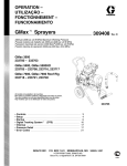
1. The Model 422A Crystal Detector (Figure 1) is a
broadband device which includes a crystal diode, a
waveguide mount designed to match approximately the
impedance of the crystal diode, and a resistor
(Option002 only) which loads the crystal for maximum
square-law range. Lossy elements in the mount reduce the SWR of the device. Model 422A detectors
are available for use in the K (18 to 26.5 GHz) and
R (26.5 to 40 GHz) bands, and can be obtained in
matched pairs.
Figure 1.
2. For optimum 8quare~law response, a separately
contained Load Resistor is supplied with Model 422A
Option 002 Crystal Detectors (see Figure 1). Each load
resistance is factory-matched to a specific Model
422A, and permits conversion from optimum squarelaw response, with the load, to optimum sensitivity,
without the load. Each Load Resistor is identified by a
serial number marked on its name-plate which is identical to the serial number of the Model 422A to which it
is matched. If you have more than one Load Resistor,
always check that you are using the proper Load Resistor for the 422A in use.
same specifications as single units, and the frequencyresponse difference between the detectors of a pair
totals no more than ±1 dB for levels below approximately 0.05 mW. Each Model 422A of a matched pair
is identified by an identical serial number marked on
its name-plate.
4. The rectified output appears at a BNC connector;
the RF input is a waveguide cover flange. For use in
systems using circular flanges, a contact flange
adapter can be supplied on 0 r d e r with Model 422A
(see Table 1). The detector in the Model 422A is a
HP developed crystal diode; replacement crystals are
supplied mounted in the required special waveguide
holder.
3. Model 422A detectors are available in matched
pairs for dual-channel applications such as reflectometer systems. Each detector of a pair meets the
Table 1.
l
MAXIMUM SWR: Model K422A: 2.5
Model R422A: 3.0
MAXIMUM INPUT: 100 mW, peak or average
OUTPUT POLARITY: Negative
SQUARE-LAW RESPONSE: Furnished with matched
load resistor for optimum square-law characteristics at 24°C (75 OF), 2 less than ±O. 5 dB variation
from square law from low level up to 50 m V peak
output working into an external load > 75K.
LOAD RESISTOR: Load Resistor: value selected
for optimum square-law response.
Model
/'
Frequency
Range
(
Specifications
SENSITIVITY: Typically 0.3 mV dC//lW CW
FREQUENCY RESPONSE: ±2 dB
Model 422A Crystal Detector and
Load Resistor
FLANGE: Cover type.
OPTION 001:Matched pair of units fitted with
square-law load. Frequency response characteristics (exclusive of basic sensitivity) track within
±1 dB2 for power levels less than approximately
0.05 mW.
OPTION 02. Furnished with matched load resistor
for optimum square-law characteristics at 24°C
(75°F),2 <±O. 5-dB variation from square law from
low level up to 50-mV peak output working into an
external load >75K. Sensitivity typically
0.1 mV//lW.
CONNECTORS:
Model 422A: BNC female
Load Resistor: ENe (one male, one female).
Mates with
Waveguide Size
Length
Equiv. Flange
JAN Type
Net
Weight
K422A3
18 - 26.5 GHz
0.500 x 0.250 in.
(12 x 64 mm)
2 in.
(51 mm)
UG595/U
9 oz
(252 gm)
3
R422A
26.5 - 40.0 GHz
0.360 x 0.220 in.
(9 x 6 mm)
2 in.
(51 mm)
UG599/U
7.5 oz
(2.1 kg)
1 As read on a meter which is calibrated for use with square-law detectors.
2 Read on a meter such as one of the HP 415 or 416 series, which is calibrated for S.quare-law detectors.
3 Circular flange adapters: K-band (UG425/U), HP 11515A, R-band (UG318/U), HP 11516A.
(
Page 3
Model 422A
SECTION II
OPERATING INSTRUCTIONS
5.
*
REFLECTOMETER MEASUREMENTS.
6. PROCEDURES. Improved techniques make it
possible to use non-matched crystal detectors in
reflectometer setups. The new techniques are described in the Hewlett-Packard Journal, Vol. 12,
No.4, a copy of which may be obtained from the
Hewlett-Packard Company on request. Use of
matched crystal detectors in a reflectometer system
is described in t~e HP Journal, Vol. 6, No. 1-2.
2
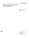
7. SIGNAL SOURCE. For reflectometer measurement systems, the RF signal must be square-wave
modulated with 1 kHz. An economical source of
modulated signals in K or R band is obtained by using
a broadband frequency doubler driven by a RF source
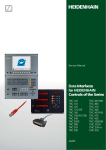
with built-in provision for 1 kHz square-wave modulation. Figure 2 shows such a combination for K band,
and Table 2 lists equipment required to obtain K- or
R-band signals with HP Models 938A and 940A
Frequency Doubler Sets. *
3
5
1.
HP Model 626A SHF Signal Generator (or
Model 8690/8694 Sweep Oscillator)
2.
HP Model 938A Frequency Doubler Set
3.
HP Model MX292B M-to-X Adapter
4.
HP 11504A Flexguide
5.
K-band Waveguide
* The filter in
the Models 938A, 940A pas s e s the
second harmonic of the input frequency, rejects the
fourth harmonic and most of the third.
The stop band in the Model 938A is fro m 31 to
80 GHz; when using the low end of the band, 18 to
20.6 GHz (input to 938A of 9-10.3 GHz) the presence
of third harmonics may make it necessary to use a
filter with a 27- to 30. 9-GHz stop band.
4
The s top band in the Model 940A is from 46 to
120 GHz; when using the low end of the band, 26.5 to
30.6 GHz (input to 940A of 13.25 to 15.3 GHz) the
presence of third harmonics may make it necessary
to use a filter with a 39.75 to 45.9 GHz stop band.
Figure 2. Using HP Model 938A Frequency
Doubler Set to Obtain Modulated
K -Band Signals
Table 2. K- and R-Band Signal Sources
Frequency
Required
Signal Source with
Mod Capabilities
Model
K band
R band
Freq. (GHz)
Adapter Required
Model
Qty.
Waveguide
Linle
Frequency ;Doubler Set
Model
626A
10 -13.25
MX292B
2
11504A
Flexguide
8694B
9 - 12.4
MX292B
1
11504A
938A
Output Freq. (GHz)
20 - 26.5
18-24.8
8695A
12.4 - 15
MP292B
1
11503A
626A
13.25 -15.5
MP292B
NP292A
1
1
11503A
Flexguide
628A
15.0-20
NP292A
2
11503A
30 - 40
8695A
13.25 -18
NP292A
1
11503A
26.5 - 36
24.8 - 30
940A
26.5 - 31
Page 4
Model 422A
/1
2
~//
11. EQUIPMENT CONSIDERATIONS.
12. INDICATOR. For applications where signal level
is low it is convenient to use an indicator such as the
HP Model 415B/E Standing Wave Indicator which is a
high-gain vol tmeter with square-law calibration.
Maximum sensitivity is obtained from the Model 422A
by setting the Model 415B/E input selector switch at
the XTAL 200K n position.
13. SIGNAL SOURCE. Since the Model 415B/E is an
audio device, the RF must be modulated at the rate of
the frequency to which the Model 415B/E input filter
is tuned; g en era 11 y this is 1 kHz. Thus the signal
source must have either an internal source of modulating voltage or an input for modulating voltage.
Signal sources such as those discussed in Paragraph 7
are sui table.
1.
HP Model 626A SHF Signal Generator (or
Model 8690/8695 Sweep Oscillator)
2.
HP Model 938A Frequency Doubler Set
3.
HP Model MX292B M-to-X Adapter
4.
HP 11504A Flexguide
5.
K-Band Waveguide
6.
HP K382A Variable Attenuator
7.
Waveguide filter under test
8.
HP Model 422A Crystal Detector and
Load Resistor
9.
HP Model 24 Waveguide Stand
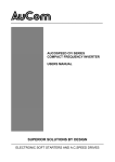
14. For most measurements, level of the signal into
the Model 422A should be low enough that crystal
response is in the square-law range (see Figure 4).
With RF input signals of -18 dBm (peak) or less, error
due to deviation from square-.law typically will be less
than a half dB when the Model 422A is operated with
its selected Load Resistor. With RF input signals of
about -18 dBm to -3 dBm, and loading resistor at·
tached, error due to deviation from square-law will be
no higher than ±l dB.
(1) As a precaution against operating the crystal
outside the square-law region, use only the
30, 40, 50, or 60 ranges of the Model 415B/E.
(2) The level of the RF into the Model 422A can
be determined apprOXimately from reading the
Model 415B/E. With the input selector at
XTAL 200K n, 3 mV into the Model 415B/E
will give a reading of at least 0 on the
30 range.
10. HP Model X25 Waveguide Clamp
11. HP Model 415B/E Standing Wave Indicator
100
Figure 3. Typical K-Band Setup for
Measuring Insertion Loss
8.
9.
MEASUREMENT OF RELATIVE POWER
LEVELS.
GENERAL.
10. When sensitivity is important, the Model 422A is
also useful for relative power measurements such as
measuring insertion loss or monitoring power level
where the power is sampled with a directional coupler.
A typical K-band setup for measuring insertion loss
is shown in Figure 3. Device under measurement is
a waveguide filter. The reference reading is made
with the fi I te r out of the line and the Model K382A
Variable Attenuator set for at least 10 dB; the setting
of the atlenuator as well as the reading of the Model
415B/E are noted. Then the filter is inserted in the
line and the attenuator adjusted to a g a i n obtain the
reference reading on the Model 415B/E. Difference
between the first and second settings of the attenuator
is the insertion loss of the filter. Characteristics
required of equipment used in a setup like that shown
in Figure 3 are discussed below.
>
E
;0
10
I-
::>
a.
I-
::>
0
0
"'
IU
w
I-
0.1
"'0
'"
«
"'a.
0.01
0
0
I0
~ 0.001
"'
/
/
/
1/
/
a.
-50
-40
PEAK
INPUT
-30
POWER
-20
IN
-10
dB (0 dB • I MW )
Figure 4. Square-Law Characteristics at
20°C of Typical 422A Crystal
o
--------
----------------------------~
Model 422A
Page 5
(3) The following typical Model 415B reading can
be used as a rough guide to determine whether
the signal into the Model 422A is low enough
to operate the crystal within its square-law
range. The reading was made with the Load
Resistor installed in the Model 422A, the
Model 415B/E GAIN control set at maximum
(full clockwise), and the input selector at
XTAL 200K 11. With a RF signal of -23 dBm
into the Model 422A, the Model 415B/E indicated approximately 2 on the 40 range.
,
~
OUTPUT--
BNC
CONTACT
SPRING - -
o
CONNECTOR
MOUNT--
15. ATTENUATOR. A variable precision attenuator,
such as the Model 382A attenuator, is required for the
measurement method briefly des c rib e d in Paragraph 10. To reduce error due to source mismatch,
connect the attenuator between source, and system and
set tbe attenuator for at least 10 dB.
16. HARMONIC FREQUENCY-COMPARISON
MEASUREMENTS.
-CRYSTAL
HOLDER
17. The Model 422A is suitable for use as a mixer in
harmonic frequency-comparison measurements. (See
HP Application Note 2.)
INSERT
SECTION III
CIRCUIT
INPUT
18. Arrangement of the Model 422A and equivalent
circuit is indicated in Figure 5. The crystal may be
considered as a voltage generator with an internal
resistance offram approximately 3K to 20K ohms and
a shunt capacitance of approximately 3 pF. The Load
Resistor is selected to obtain the maximum range of
square-law operation with inputs of up to half a milliwatt average.
E;t
VIDEO
LOAD
(OPTION 02)
VIDEO
OUTPUT
VIDEO LOAD
(OPTION 02)
R
3K-20K
~ ~LOAD RESISTOR
i LOAD SELECTED
i
~g~A~TI~~:
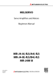
Figure 6.
B.
Exploded View of Model 422A
Crystal Detector
21. REPLACEMENT OF PARTS.
22. Procedure for replacing the BNC connector on the
detector mount is covered in Paragraph 24, and replacing those on the Load Resistor in Paragraph 27. For
additional maintenance information contact the
Hewlett-Packard Company of your local HP field
office.
23. Stock numbers for replaceable parts are given in
Table 3, Section V.
! RESPONSE
24. REPLACING BNC CONNECTOR.
25. TOOLS REQUIRED.
LOSSY DIELECTRIC
a. Needle -point soldering iron
422A CIRCUIT
Figure 5. Arrangement of 422A and
Equivalent Circuit
b. Wire cutters
c. Flat file, #4
d. Tweezers.
SECTION IV
MAINTENANCE
19. PREVENTIVE MAINTENANCE.
20. Pro tee t tbe face of the coupling flange fro m
damage. Any scoring or burring of the mating surfaces causes discontinuity. The resulting increase
in SWR degrades performance.
26. PROCEDURE. Parts mentioned in the following
procedure are identified in Figures 6 and 7.
a. Remove BNC connector; type UG-88/U mating
male connector may be used to loosen the female.
b. Unsolder contact spring sol d ere d to center
conductor lead.
c. Prepare replacement BNC connector:
(1) Cut center conductor lead to approximately
1/32 inch (see Figure 7.)
Page 6
Model 422A
CONTACT
SPRING
27. REPLACEMENT OF BNC
CONNECTORS.
---~
,,%
tJ{
"
1/32"
Figure 7. Cutting BNC Connector Center
Conductor Lead to Accommodate Contact Spring
28. Parts referred to in the following procedures are
identified in Figures 7 and 8.
29. REPLACING MALE BNC CONNECTOR.
a. Remove male BNe connector from housing. To
remove BNC use a 3lB-inch open-end wrench and hold
the housing either in a vise or with gas pliers. Before
putting pliers on protect the housing of the Load Resistor with material such as heavy paper.
d. Slip contact spring over center conductor lead,
and solder. CAUTION: Use solder sparingly or it
will creep back on spring. Solder on spring destroys
its usefulness, and solder is diffucult to remove from
spring.
e. Let spring cool, and then screw the connector
into the mount.
f. CHECKING. After the new BNC is installed,
check for ali g n men t of the leaf spring and crystal
lead by measuring the resistance across the BNe
connector.
CAUTION
Use a low-current ohmmeter such as
the HP Model 410B.
"
d. Let resistor cool and then check res i s tan c e
from male BNC pin through resistor.
e. Replace lockwasher and male BNC.
30. REPLACING FEMALE BNC CONNECTOR. To
remove and install ,a BNC connector use a BNC wrench
or use a male BNC connector as a wrench.
a. Remove BNC connector.
b. Unsolder contact spring.
c. Prepare replacement BNC connector:
(1) Cut center conductor lead to approximately
1/32-inch.
(2) With flat file, s moo t h end of lead; wipe off
burr with tweezers or similar metal
instrument.
d. Slip contact spring over center conductor lead,
and solder.
CAUTION
(1) Set the 0 h m mete r for the RX100 or higher
range. Connect one ohmmeter lead to the
BNC c en t e r conductor and the other to the
BNC shell.
Use solder sparingly or it will creep back
on spring. Solder on spring des t roy s its
usefulness and solder is difficult to remove
from spring.
(2) Take a reading. Reverse the leads and take
another reading.
e. Let can ta c t spring cool, and then screw the
connector into the mount.
(a) Normal. There will be a reading of a few
hundred ohms in one direction and tens of
thousands of ohms in the other.
SPRING
(b) No reading. The leaf spring is not making
contact with the crystal lead. Remove the
BNC connector (a mating male connector
may be used to loosen the female), stretch
the leaf spring, rei n s tall the BNC, and
again measure the resistance.
(c) Low reading. If the reading is very lOW,
the leaf spring probably is touching the side
of the mount. Remove the BNC, adjust the
spring so it will center in the opening, reinstall the BNC, and again mea sur e the
resistance.
1
i
b. Unsolder resistor.
c. Solder resistor to new BNC.
(2) With flat file, smooth end of lead; wipe off
burr with tweezers or similar metal
instrument.
(
WASHER
o
FEMALE BNC
Figure 8. Load Resistor,
Cutaway View
Page 7
Model 422A
3 lists the manufacturer's name and the total
quantity (TQ) used in the instrument.
31. REPLACEMENT OF CRYSTAL HOLDER
32. Parts referred to in the following procedure
are identified in Figure 6. To replace the crystal
holder, proceed as follows:
a.
Remove the four screws from the waveguide input section.
b.
Remove waveguide input section.
c.
Remove the crystal holder.
d.
Check that the contact to the BNC
connector center conductor is bright and
clean. If not, burnish with fine sandpaper
and wipe clean with cloth.
e.
Install the new crystal holder with the
polyiron insert facing toward the waveguide input.
f.
Replace waveguide input section and
secure with the four screws.
35. ORDERING INFORMATION
36. To order a replacement part, address order or
inquiry either to your nearest Hewlett-Packard
field office (see lists on following page) or to
CUSTOMER SERVICE CENTER
Hewlett-Packard Company
333 Logue Ave.
Mt. View, California 94040
Of,
in Western Europe, to
HPGmbH
Technisches Buero Boblingen
Herrenbergerstrasse 110
D-7030 Boblingen, Wurttemberg
37. Specify the following for each part:
SECTION V
REPLACEABLE PARTS
33. INTRODUCTION
(,
34. This section contains information on ordering
replacement parts for the Model 422A and Load
Resistor. In addition to identifying the part, Table
a.
Model and serial number of the device.
b.
c.
HP Part number, and Check Digit (CD).
Description.
38. To order a part not listed in Table 3, give a
complete description of the part.
Table 3. Replaceable Parts, Model 422A and Load Resistor
HP Part Number
Description
K422A
CD
R422A
CD Load Resistor
Crystal Kit (Loaded)
00422-60005
7
00422-60007
9
Crystal Kit (Matched pair with squarelaw load)
00422-60006
8
00422-60008
0
Polyiron Disk
00422-20004
2
00422-20004
2
Connector, male BNC, includes rubber ring
1250-0045
5
Connector, female, BNC, includes
lockwasher
1250-0083
1
1250-0083
1
1250-0251
5
Spring, contact
5000-0234
9
5000-0234
1
5000-0234
9
Screw, 4-40 x 5/8 fillister, stainless steel
TQ
(
CD
=
Total quantity used in instrument
4 (TQ)
4 (TQ)
CERTIFICATION
Hewlett-Packard Company certifies that this product met its published specifications at the time of shipment from the
factory. Hewlett-Packard further certifies that its calibration measurements are traceable to the United States National
Bureau of Standards, to the extent allowed by the Bureau's calibration facility, and to the calibration facilities of other
International Standards Organization members.
(
WARRANTY
This Hewlett-Packard instrument product is warranted against defects in material and workmanship for a period of one
year from date of shipment. During the warranty period, Hewlett-Packard Company will, at its option, either repair or
replace products which prove to be defective.
For warranty service or repair, this product must be returned to a service facility designated by HP. Buyer shall prepay
shipping charges to HP and HP shall pay shipping charges to return the product to Buyer. However, Buyer shall pay all
shipping charges, duties, and taxes for products returned to HP from another country_
HP warrants that its software and firmware designated by HP for use with an instrument will execute its programming
instructions when properly installed on that instrument. HP does not warrant that the operation of the instrument, or
software, or firmware will be uninterrupted or error free.
LIMITATION OF WARRANTY
The foregoing warranty shall not apply to defects resulting from improper or inadequate maintenance by Buyer,
Buyer-supplied software or interfacing, unauthorized modification or misuse, operation outside of the environmental
specifications for the product, or improper site preparation or maintenance.
NO OTHER WARRANTY IS EXPRESSED OR IMPLIED. HP SPECIFICALLY DISCLAIMS THE IMPLIED
WARRANTIES OF MERCHANTABILITY AND FITNESS FOR A PARTICULAR PURPOSE.
EXCLUSIVE REMEDIES
THE REMEDIES PROVIDED HEREIN ARE BUYER'S SOLE AND EXCLUSIVE REMEDIES. HP SHALL NOT BE
LIABLE FOR ANY DIRECT, INDIRECT, SPECIAL, INCIDENTAL, OR CONSEQUENTIAL DAMAGES,
WHETHER BASED ON CONTRACT, TORT, OR ANY OTHER LEGAL THEORY.
ASSISTANCE
Product maintenance agreements and other customer assistance agreements are available for Hewlett-Packard
products.
HEWLETT-PACKARD SERVICE OFFICES
To obtain servicing information, contact the nearest Hewlett-Packard Sales and Service Office in HP Catalog, or
contact the nearest regional office listed below.
UNITED STATES
NO. CALIFORNIA (San Franciaco Area)
333 Logue Ave.
Mt. View, CA 94043
SO. CALIFORNIA (Los Angeles Area)
5400 West Rosecrans Blvd.
Lawndale, CA 90260
GEORGIA
450 Interstate N. Parkway
Atlanta, GA 30348
ILLINOIS
5201 Tollview Dr.
Rolling Meadows, IL 60008
NEW JERSEY
W. 120 Century Rd.
Paramus, NJ 07652
AUSTRALIA
Hewlett-Packard Australia Ltd.
31-41 Joseph Street
Blackburn, Victoria 3130
CANADA
NETHERLANDS
Hewlett-Packard (Canada) Ltd.
6877 Goreway Drive
Miasissauga, Ontario
Canada UV IM8
Hewlett-Packard Benelux N.V.
Van Heuven Doedhartlaan 121
P.O. Box 667
NL-Amstelveen 1134
ITALY
Hewlett-Packard Italiana S.p.A.
Via G. Di Vittorio, 9
20063 Cernusco
SuI Na~glio (MI)
FRANCE
Hewlett-Packard France
Quartier de Courtaboeuf
Boite Postale No.6
F-91401 Orsay Cedex
GERMAN FEDERAL REPUBLIC
Hewlett-Packard GmbH
Vertrisbazentrale Frankfurt
Bernsratrasse 117
Postfach 560 140
D-6000 Frankfurt 56
UNITED KINGDOM
Hewlett-Packard Ltd.
King Street Lane
GB-Winnersh, Wokingham
Bers, RG115AR
AFRICA, ASIA, CENTRAL AND
SOUTH AMERICA
Hewlett-Packard Intercontinental
3200 Hillview Avenue
Palo Alto, CA 94304
{hpi PACKARD
----
HEWLETT
MANUAL PART NO. 00422·90009
Microfiche Part No. 00422·90011
Printed in U.S.A.
(