1
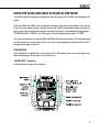
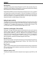
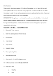
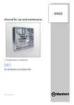
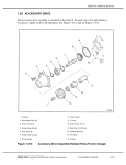
8240A and 8250A DSP Loudspeakers Operating Manual
INTRODUCTION
Congratulations and a thank-you for the purchase of this Genelec 8200 Series DSP Loudspeaker. These
systems are designed to integrate easily into the digital production environment. There are several ways
to configure and operate the DSP loudspeakers for a wide variety of high quality audio applications. The
loudspeakers also have analog inputs, making them versatile and intelligent replacements for analog
loudspeakers.
This manual addresses setting up and using the 8240A and 8250A DSP loudspeakers in stand-alone
mode without the Genelec Loudspeaker Manager GLM™ and the proprietary Genelec loudspeaker
control network. Use with the GLM™ is described in the DSP System Operating Manual.
EC Declaration Of Conformity
This is to certify that Genelec 8240A and 8250A DSP loudspeakers conform to the following standards:
Safety: EN 60065: 2002 / IEC 60065:2001 7th Edition
EMC: EN 55020 : 2002 + A1 : 2003, EN 55013: (2001), EN 61000-3-2 (2000) and EN 61000-3-3 (1995)
The products herewith comply with the requirements of The Low Voltage Directive 73/23/EEC, EMC
Directive 89/336/EEC and 93/68/EEC
Signed:
Position:
Date:
Ilpo Martikainen
Chairman of the Board
20-February-2006
Compliance to FCC Rules
This device complies with part 15 of the FCC Rules. Operation is subject to the following two conditions:
•
•
This device may not cause harmful interference, and
This device must accept any interference received, including interference that may cause
undesired operation.
Note: This equipment has been tested and found to comply with the limits for a Class B digital device,
pursuant to part 15 of the FCC Rules. These limits are designed to provide reasonable protection against
harmful interference in a residential installation. This equipment generates, uses and can radiate radio
frequency energy and, if not installed and used in accordance with the instructions, may cause harmful
interference to radio communications. However, there is no guarantee that interference will not occur in a
particular installation. If this equipment does cause harmful interference to radio or television reception,
which can be determined by turning the equipment off and on, the user is encouraged to try to correct the
interference by one or more of the following measures:
•
•
•
•
Reorient or relocate the receiving antenna.
Increase the separation between the equipment and receiver.
Connect the equipment into an outlet on a circuit different from that to which the receiver is
connected.
Consult the dealer or an experienced radio/TV technician for help.
Modifications not expressly approved by the manufacturer could void the user’s authority to operate the
equipment under FCC rules.
SYSTEM
Genelec 8240A and 8250A DSP Loudspeakers are designed for precise monitoring of 24 bit/192
kHz AES/EBU digital audio signal or line level analog audio signal. They are fully compatible with
Genelec Loudspeaker Manager GLM™ and the proprietary Genelec loudspeaker control network, and
Genelec 7260A, 7270A and 7271A DSP Active Subwoofers, but can also be used independently of
these. The 8240A and 8250A feature high SPL output, low colouration and broad bandwidth in a small
enclosure size. They are suitable for a wide variety of tasks, such as near field monitoring, mobile vans,
broadcast and TV control rooms, surround sound systems and home studios. The Minimum Diffraction
Enclosure™ (MDE™) and advanced Directivity Control Waveguide™ (DCW™) technologies provide
excellent frequency balance even in difficult acoustic environments.
Drivers
The bass driver dimensions are 165 mm (6 1/2”) and 205 mm (8") for 8240A and 8250A respectively. The
long, flow optimized reflex tube has a large cross sectional area and terminates with a wide flare at the
back of the enclosure. The high frequency driver is a 19 mm (3/4”) metal dome on the 8240A and a 25
mm (1") metal dome on the 8250A. All drivers are magnetically shielded.
Amplifiers
The amplifier unit is mounted in the rear of the loudspeaker enclosure. The unit incorporates special
circuitry for driver thermal overload protection. Variable input sensitivity allows accurate level matching to
console output section.
USING THE 8240A AND 8250A IN STAND-ALONE MODE
The 8240A and 8250A accept both analogue line level input signals and AES/EBU formatted digital input
signals.
When the 8240A and 8250A are not connected to Genelec loudspeaker control network, they operate
in the stand-alone mode. However, settings made with the Genelec Loudspeaker Manager software can
be saved into each loudspeaker and applied even when the network is disconnected by setting switch 1
“STORED/MANUAL CONTROL” on switch group 2 of each loudspeaker to position “STORED.”
This manual concentrates on using the 8240A and 8250A without the control network. All issues concerning
use with the network are explained in detail in the System Operating Manual provided with the GLM™
Loudspeaker Manager software kit.
Connections
Each loudspeaker is supplied with a mains cable, one 5 m GLM network cable and an operating manual.
Before connecting up, ensure that the mains switch is off.
“MAINS INPUT” connector
Connect the mains supply to this connector.
“DIGITAL IN AES/EBU” connector
Use this female XLR connector for AES/EBU formatted digital audio input signals. This input is selected
automatically when a valid digital audio signal is present, and overrides the analogue input.
Depending on the digital hardware, transmission of a 192 kHz sample rate is achieved using a double
speed, single channel/cable interface. This is called dual-wire mode. In this case one cable per channel is
used and no channel selection is required. Dual-wire mode is automatically detected by the input stage.
If the digital source device has a digital level monitor pot or graphical volume fader that controls the
digital level, it may be advantageous to lower the level control either on the computer interface or the
loudspeaker’s back panel controls, which in turn will force the use of more of the digital [bit] resolution in
the volume control.
If the digital inputs are used, all audio outputs are referenced to 0 dBFS (digital Full Scale, the largest
level that may be represented in the AES/EBU signal). Genelec DSP loudspeakers produce 100 dB SPL
at 1 meter in free space for a digital input signal of –30 dB FS. It is advantageous to keep the digital level
as high as possible.
“DIGITAL THRU AES/EBU” connector
This male XLR carries an unaltered copy of the digital signal fed into the “DIGITAL IN AES/EBU” connector.
It can be used for daisy-chaining up to four loudspeakers together.
“ANALOG IN” connector
Use this connector for analog audio signals. When operating an 8200 Digital system in the analog mode the
A/D converter must not be overloaded, otherwise distortion will be heard. The maximum input level is +7.0
dBu RMS (+11 dBu peak). When A/D converter input clip occurs the front panel light turns momentarily
red, indicating the overload condition.
If the “Level” control on the 8200 back panel is reduced (turned counter-clockwise), the acoustic output will
be reduced. This control decreases the output from the D/A converters. Ideally the Level control should
be set to force the use of more of the input range of the A/D converter without overloading it. Remember,
there is no headroom above the maximum input to the A/D conversion.
“CONTROL NETWORK” connectors
Use these RJ-45 sockets to connect the loudspeaker to the proprietary Genelec Loudspeaker Manager™
(GLM™) network only. This connector is not Ethernet LAN compatible. Do not connect to Ethernet LAN.
Front panel warning light
Normally the light on the front panel of an 8200 loudspeaker is green, indicating that the loudspeaker is
in normal operational mode.
The overload light (red) is activated by several events,
•
exceeding the maximum input range of the analog input
•
exceeding the maximum input range of the digital input with large probability
•
exceeding the output capacity of the power amplifier (clipping in the power amplifier) and thermal
overload of the power amplifier or loudspeaker drivers (thermal protection has activated)
•
if an error is detected in the AES/EBU audio data
If a red warning light appears, turn the analog source down! If the levels are already modest and a digital
signal is being used, ensure that there are no bit errors in the AES/EBU digital audio data.
MOUNTING CONSIDERATIONS
Align the loudspeakers correctly
Always place the loudspeakers so that their acoustic axes are aimed towards
the listening position. Vertical placement is preferable, as it minimises acoustical
cancellation problems around the crossover frequency.
Maintain symmetry
Check that the loudspeakers are placed symmetrically and at an equal distance
from the listening position. If possible, place the system so that the listening
position is on the centerline of the room and the loudspeakers are placed at an
equal distance from the centerline.
Minimise reflections
Acoustic reflections from objects close to the loudspeakers like desks, cabinets, computer monitors etc.
can cause unwanted colouration and blurring of the sound image. These can be minimised by placing
the loudspeaker clear of reflective surfaces. For instance, putting the loudspeakers on stands behind and
above the mixing console usually gives a better result than placing them on the meter bridge. Symmetrical
positioning of the reflective objects is also importent in order to maintain a balanced soundstage.
Minimum clearances
Sufficient cooling for the integrated amplifier and functioning of the reflex port must be ensured if the
loudspeaker is installed in a restricted space such as a cabinet, or integrated into a wall structure. The
surroundings of the loudspeaker must always be open to the listening room with a minimum clearance
of 5 centimeters (2") behind, above and on both sides of the loudspeaker. The space adjacent to
the loudspeaker must either be ventilated or sufficiently large to dissipate heat so that the ambient
temperature does not rise above 35 degrees Celsius (95°F).
Mounting options
The vibration insulating Isolation Positioner/Decoupler™ (Iso-Pod™) table stand allows tilting of the
loudspeaker for correct alignment of the acoustic axis. The stand can be attached to three mounting
points allowing vertical and symmetrical horizontal positioning.
Genelec 8240A and 8250A can be fitted to König & Meyer loudspeaker mounts on two sets of M6x10
mm threaded holes on the back of the enclosure. On the base of the enclosure is an M10x10 mm
threaded hole which can be used for securing the loudspeaker to its base. Do not use this thread for
mounting the loudspeaker on a microphone stand which has a 3/8" UNC thread. A wide variety of
ceiling and wall mounts is available through your Genelec dealer.
Setting the input sensitivity
The loudspeaker level sensitivity functions for both analog and digital input. The sensitivity can be matched
by adjusting the rotary Level control together with the System Level switches located in the switch group
2. (switches 6 and 7). The switches provide attenuation levels of -10 dB (sw. 6 ON), -20 dB (sw. 7 ON)
and -30 dB (both switches ON) The combined attenuation ranges from 0 to -42 dB.
Functions on switch group 1 (Tone controls)
Switch group 1 (the upper switch group) comprises the tone controls that can be used to adjust the
frequency response of the system in stand-alone mode to match the acoustic environment. The
controls are labelled "TREBLE TILT", "BASS TILT", "BASS ROLL-OFF" and “DESKTOP”. The factory
settings for these controls are all "OFF" to give a flat anechoic response. Note that these controls have
no effect when switch 1 “STORED/MANUAL CONTROL” on switch group 2 is set to “STORED” or
when the loudspeaker is connected to the Genelec loudspeaker control network.
Bass Roll-Off control
Bass Roll-Off control (switches 1 and 2) affects the low frequency roll-off of the loudspeaker and attenuates
its output near the cut-off frequency. Attenuation levels of -2 dB (sw. 1 ON), -4 dB (sw. 2 ON) or -6 dB
(both switches ON) can be selected.
Bass Tilt control
The Bass Tilt control switches (swiches 3 and 4) offer three attenuation levels for the bass response below
800 Hz, usually necessary when the loudspeakers are placed near room boundaries. The attenuation levels
are -2 dB, -4 dB and -6 dB.
Desktop low frequency control
The desktop low frequency control (switch 5) attenuates the bass frequencies around 160 Hz by 4 dB.
This feature is designed to compensate for the boost often occurring at this frequency range when the
loudspeaker is placed upon a meter bridge, table or similar reflective surface.
Treble Tilt control
Treble Tilt control (switches 6 and 7) allows adjusting the treble response above 5 kHz by +2 dB, -2 dB or
-4 dB, which can be used for correcting an excessively bright or dull sounding system or to compensate
for high frequency level loss if the loudspeaker is placed behind a screen.
An acoustic measuring system such as MLSSA or WinMLS is recommended for analyzing the effects of
the adjustments, however, careful listening with suitable test recordings can also lead to good results if a
test system is not available. The table below shows some typical settings in various situations.
Always start adjustment by setting all switches to "OFF” position. Measure or listen systematically through
the different combinations of settings to find the best frequency balance. See table below for some typical
settings in various situations. Please note that the GLM Loudspeaker Controller allows a much more
versatile and precise set of controls to be used, and supports the fully automatic system alignment feature,
the Genelec AutoCal.
Loudspeaker Mounting Position
Treble Tilt
Bass Tilt
Bass Roll-Off
Desktop
Flat anechoic response
None
None
None
None
Free standing in a damped room
None
-2 dB
None
None
Free standing in a reverberant
room
None
-4 dB
None
None
Near field on a reflective surface
None
-2 dB
None
-4 dB
In a corner
None
-4 dB
-4 dB
None
Functions on Switch Group 2
Stored / Manual Ctrl
This allows the selection between two basic methods of controlling the loudspeaker in the stand-alone
mode. “MANUAL CTRL” refers to controlling the loudspeaker using the controls on the loudspeaker’s
back panel. The “STORED” refers to using settings stored inside the memory of the loudspeaker. These
settings are made using the GLM and the GLM Control Network. There is additional functionality compared
to that offered by the room response correction switches on the back panel.
Selection
Switch Function
Bass
Roll-Off
Bass Tilt
Desktop
Treble Tilt
AES/EBU
Driver
Mute
System.
Level
STORED
Disabled
Disabled
Disabled
Disabled
Disabled
Active
Disabled
MANUAL
CTRL
Active
Active
Active
Active
Active
Active
Active
AES/EBU CH
This selects the audio channel(s) available on the AES/EBU cable to be reproduced by the loudspeaker.
Turning both switches on reproduces the sum of the two channels on the AES/EBU cable. Turning both
switches off has the same effect which has been done deliberately to avoid the situation where no input
channel is selected and the loudspeaker is effectively muted. When two channels are selected, 6 dB of
attenuation is automatically applied to avoid overloading the loudspeaker.
If the AES/EBU cable is operated in dual-wire mode (typically 192 kHz sampling frequency) one AES/
EBU cable carries only one audio channel. The loudspeaker detects this situation automatically and the
channel selection switches have no effect.
Driver Mute
These two switches allow you to mute the treble driver (marking TW) and bass driver (marking WF)
independently. This may be useful to diagnose if a transducer is faulty.
System Lvl
These switches allow scaling down of the loudspeaker output. The signal sent to the “Thru” output
connector is not affected. The switches are additive, for example, “–30 dB” attenuation is achieved by
turning on the “–10 dB” and “–20 dB” switches. The effect of these switches is combined with the effect of
the rotary level adjustment control. This results in total possible attenuation of 42 dB, 30 dB by the system
level switches and another 12 dB by the rotary control.
Using 7000 Series Analog Subwoofers with 8200 Series DSP Loudspeakers
Please follow the steps below to integrate an analog subwoofer into a system of DSP loudspeakers:
•
Connect cables carrying analog audio to the 7000 Series analogue subwoofer first.
Connect the subwoofer outputs to the analog inputs of the 8200 Series DSP main loudspeakers.
•
•
Connect the GLM Control Network to the main loudspeakers.
•
Make a System Setup in GLM. It will consist of main loudspeakers as this is all the network
can see, so suitable Rapid Cabling Presets are “Stereo Pair (Analog)” and “5.0 Surround System
(Analog)”.
•
Run AutoCal and review and the results to check for large dips at or above 85Hz. Move the
loudspeakers and repeat AutoCal if there is a problem.
•
Press “Finish”, then in the Main Page select “Menu | Store Acoustic Settings to All Online
Loudspeakers” and close GLM.
•
For each DSP loudspeaker, turn it off, select “Stored” on the back of each loudspeaker to enable
the internal Acoustic Settings, and then turn it on again.
•
To set the phase control on the subwoofer, connect the Center channel output of the subwoofer
to the loudspeaker to be used to align phase.
•
Follow the instructions in the subwoofer user manual for setting phase and level.
Maintenance
No user serviceable parts are to be found within the loudspeaker enclosure. Any maintenance or repair
of the loudspeaker should only be undertaken by qualified service personnel.
Safety considerations
Although the 8240A and 8250A have been designed in accordance with international safety standards,
to ensure safe operation and to maintain the loudspeaker under safe operating conditions, the following
warnings and precautions must be observed:
1.
2. 3. 4. 5. Servicing and adjustment must only be performed by qualified service personnel.
The loudspeaker enclosure must not be opened.
Do not use this product with an unearthed mains cable or a mains connection without the
protective earth contact as this may lead to personal injury.
To prevent fire or electric shock, do not expose the unit to water or moisture.
Do not place any objects filled with liquid, such as vases on the loudspeaker or near it.
Note that the amplifier is not completely disconnected from the AC mains service unless
the mains power cord is removed from the amplifier or the mains outlet.
Free flow of air behind the loudspeaker is necessary to maintain sufficient cooling.
Do not obstruct airflow around the loudspeakers.
WARNING!
Genelec 8240A and 8250A loudspeakers are capable of producing sound pressure levels in excess of
85 dB, which may cause permanent hearing damage.
Guarantee
Genelec 8240A and 8250A are supplied with one year guarantee against manufacturing faults or defects
that might alter the performance of the loudspeakers. Refer to supplier for full sales and guarantee terms.
8240A Accessories
Order code
8000-408 8000-401B 8000-401W 8000-402B 8000-402W 8000-406 8040-408 8000-415B 8000-417B 8000-419B 8000-418B 8040-420 8040-450
Description
Floor stand (K&M 26740-000-58)
Wall mount, black (K&M 24180-000-55)
Wall mount, white (K&M 24180-000-57)
Wall bracket, black (K&M 24475-000-55)
Wall bracket, white (K&M 24475-000-57)
Table stand (K&M 23310-370-55)
Stand plate for 8040 Iso-Pod (K&M 19624-300-55)
Ceiling mount, black (K&M 24490-000-55)
Truss mount kit, black (K&M 24495-000-55)
Adapter for 36 mm tube, black (K&M 24521-300-55 )
Security wire, (K&M 24521-901-55)
Soft carrying bag for two loudspeakers
Flush mount kit
8250A Accessories
Order code
8000-408 8000-402B 8000-402W 8050-408 8000-415B 8000-417B 8000-419B 8000-418B 8050-420 8050-450
Description
Floor stand (K&M 26740-000-58)
Wall bracket, black (K&M 24475-000-55)
Wall bracket, white (K&M 24475-000-57)
Stand plate for 8050 Iso-Pod (K&M 19625-300-55)
Ceiling mount, black (K&M 24490-000-55)
Truss mount kit, black (K&M 24495-000-55)
Adapter for 36 mm tube, black (K&M 24521-300-55 )
Security wire, (K&M 24521-901-55)
Soft carrying bag for one loudspeaker
Flush mount kit
Not all accessories available in all regions. Consult region specific website or your local distributor/dealer
for complete list of 8200 Accessories in your country.
10
SPECIFICATIONS
8240A
8250A
Lower cut-off frequency, -3 dB
Upper cut-off frequency, -3 dB
≤ 45 Hz
≥ 21 kHz
≤ 35 Hz
≥ 21 kHz
Free field frequency response of system (± 1.0 dB)
48 Hz - 20 kHz
38 Hz - 20 kHz
Maximum short term sine wave acoustic output on axis in half
space, averaged from 100 Hz to 3 kHz
@1m
@0.5 m
≥ 105 dB SPL
≥ 111 dB SPL
≥ 110 dB SPL
≥ 116 dB SPL
Maximum long term RMS acoustic output in same conditions with
IEC weighted noise (limited by driver unit protection circuit) @1 m
≥ 99 dB SPL
≥ 101 dB SPL
Maximum peak acoustic output per pair above console top, @1 m
from the engineer with music material
≥ 115 dB SPL
≥ 120 dB SPL
Self generated noise level in free field @1m on axis (A-weighted)
≤ 10 dB
≤ 10 dB
Harmonic distortion at 90 dB SPL @1m on axis
50 to 100 Hz
> 100 Hz
<2%
< 0.5 %
<2%
< 0.5 %
Drivers:
Bass
Treble
Both drivers are magnetically shielded
165 mm (6 1/2")
19 mm (3/4")
metal dome
205 mm (8")
25 mm (1")
metal dome
Weight:
9.4 kg (20.8 lbs)
14.6 kg (32 lbs)
Dimensions:
Height (without Iso-Pod table support)
Height (including Iso-Pod table support)
Width
Depth
350 mm (13 13/16“)
365 mm (14 3/8“)
237 mm (9 3/8“)
223 mm (8 13/16“)
433 mm (17 1/16")
452 mm (17 13/16")
286 mm (11 1/4")
278 mm (10 15/16")
11
8240A
8250A
Analog audio input connector
XLR female, pin 1 gnd, pin 2 +, pin 3 -
Analog audio input impedance
10 kOhm balanced
Input level for maximum short term output of 100 dB SPL @ 1m
Adjustable from +6 to -6 dBu
Crossover frequency, Bass/Treble
3.0 kHz
1.8 kHz
Treble Tilt control operating range in 2 dB steps
+2 to -4 dB & MUTE
@ 15 kHz
+2 to -4 dB & MUTE
@ 15 kHz
Desktop low frequency control operating range
-4 dB @ 160 Hz
-4 dB @ 160 Hz
Bass Roll-Off control operating range in 2 dB steps
0 to -6 dB @ 45 Hz
From 0 to -6 dB @ 35 Hz
Bass Tilt control operating range in 2 dB steps
0 to -6 dB & MUTE
@ 100 Hz
0 to -6 dB & MUTE
@ 100 Hz
The 'CAL' position is with all tone controls set to 'off'
and the input sensitivity control to maximum (fully
clockwise)
8240A
8250A
Digital audio input connector
XLR female
Digital audio input impedance
110 Ohm
Digital audio Thru output connector
XLR male
Digital audio Thru output impedance
110 Ohm
Digital audio format
AES/EBU (AES3-2003)
Can also be used with S/P-DIF and AES3id signals
when impedance converters are used
Digital audio word length
16 bits, maximum 24 bits.
Fixed point, AES/EBU format
Digital audio sample rate
32 kHz, maximum 192 kHz
Supports single-wire and dual-wire AES signals.
AD conversion dynamic range
122 dB
Gain-ranging operation in two gain ranges; converter
dynamic range 112 dB typical
12
The curves above show the effect of the “Bass Tilt”, “Treble Tilt”,
“Desktop Low Frequency” and “Bass Roll-Off” controls on the
free field response of the 8240A.
The upper curve group shows the horizontal directivity characteristics
of the 8240A measured at 1 m. The lower curve shows the system's
power response.
The curves above show the effect of the “Bass Tilt”, “Treble Tilt”,
“Desktop Low Frequency” and “Bass Roll-Off” controls on the
free field response of the 8250A.
The upper curve group shows the horizontal directivity characteristics
of the 8250A measured at 1 m. The lower curve shows the system's
power response.
13
Designed to Adapt
Genelec Document D0048R001c. Copyright Genelec Oy 11.2007. All data subject to change
750-8240A/8250A rev C