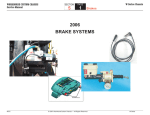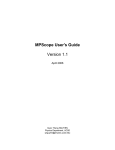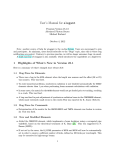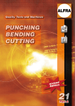
1
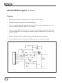
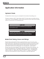
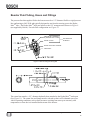
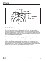
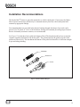
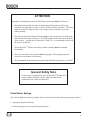
Hydro-Max™ Hydraulic Brake Booster and Master Cylinder Technical Manual BOSCH Important Service Notes The information in this publication was current at the time of printing. The information presented in this publication is subject to change without notice or liability. The information contained in this publication is intended for use by properly trained and equipped professional technicians. It is NOT for the "Do It Yourselfer". Failure to follow safety and repair procedures can result in personal injury, or damage to vehicles, components and equipment. Correspondence concerning this manual should be addressed to: Robert Bosch LLC Attn: Medium Truck Brake Engineering 3737 Red Arrow Highway St. Joseph, Michigan 49085 This manual can be viewed or downloaded at: http://www.bosch.us Fax: 269-428-6704 August 2003 Hydro-Max Technical Manual 2 Table of Contents General Description.............................................................................................................................1 Hydro-MaxTM Booster................................................................................................ 1 Master Cylinder.........................................................................................................1 Principle of Operation........................................................................................................................ 3 Hydro-MaxTM Booster................................................................................................ 3 Master Cylinder.........................................................................................................5 Electrical Operating System......................................................................................7 Basic Operation of Booster and Master Cylinder......................................................8 Electronic Monitor Module........................................................................................9 Application Information...................................................................................................................... 13 Hydraulic Fluids........................................................................................................13 Brake Fluid Tubing, Hoses and Fittings....................................................................13 Booster Fluid Tubing, Hoses and Fittings.................................................................14 Booster Fluid Source..................................................................................................15 Installation Recommendations...................................................................................16 Pedal Return Springs.................................................................................................17 Pedal Stop and Proper Spring Load..........................................................................18 Trouble Shooting..................................................................................................................................19 Printed in the United States of America © 2002 Robert Bosch Corp. All rights reserved. Hydro-Max Technical Manual 3 General Description The Hydro-MaxTM is a hydraulically powered brake booster which provides power assist for applying hydraulic brakes. A booster combined with a master cylinder (refer to Figure 1) forms the hydraulic brake actuation unit. A typical assembly is shown in Figure 1. The booster reduces the pedal effort required to apply the brakes as compared to a non-power system. BRAKE FLUID RESERVOIR FLOW SWITCH INLET PORT PEDAL ROD OUTLET PORT MOUNTING FLANGE MASTER CYLINDER HYDRO-MAXTM BOOSTER SECONDARY OUTLET PORT BACKUP PUMP DIFFERENTIAL PRESSURE SWITCH RELAY FLUID LEVEL INDICATOR SWITCH PRIMARY OUTLET PORT Figure 1 Hydro-MaxTM Booster and Master Cylinder Assembly Hydro-MaxTM Booster The hydraulic booster is comprised of an open center valve and reaction feedback mechanism, a power piston, a 12 and 24-volt backup pump and an integral flow switch. It is powered by either the power steering pump or other hydraulic source. The backup pump provides a secondary power source for the hydraulic booster and is controlled by the integral flow switch. Master Cylinder The master cylinder is a split system type with separate fluid chambers, pistons and outlet ports for the front and rear brake circuits. A differential pressure switch, fluid level indicator switch, and remote reservoir are also available. A typical Hydro-MaxTM booster and master cylinder assembly installation in a hydraulic braking system is shown in Figure 2. Hydro-Max Technical Manual 41 Hydro-Max Technical Manual 52 STEERING PUMP RESERVOIR & FILTER TO WARNING SYSTEM TO WARNING SYSTEM Figure 2 ABS UNIT TO REAR BRAKES TO REAR BRAKES TO BATTERY BRAKE SWITCH Typical Booster and Master Cylinder Assembly Installation in a Hydraulic Braking System TO FRONT BRAKES TO FRONT BRAKES STEERING GEAR FLOW N OF CTIO E IR D GROUND TO IDP TO IGNITION ( OPTIONAL) MONITOR MODULE TO WARNING LIGHT TO WARNING BUZZER Principle of Operation Hydro-MaxTM Booster During normal system operation, (refer to Figure 4) fluid flow from a hydraulic power source (usually the power steering pump) enters the inlet port of the Hydro-MaxTM booster, flows through the power piston, around the throttle valve and through the flow switch, exiting through the outlet port. Force applied to the brake pedal by the vehicle operator is multiplied by the lever ratio of the pedal mechanism to move the pedal rod of the booster. This movement closes the throttle valve, which restricts flow. This restriction of flow, which results in a pressure increase acting on the power piston, applies an amplified force to the master cylinder primary piston. A reaction piston, inside the power piston subassembly, provides the driver "pedal feel" during an application of the brake pedal. Fluid flow through the flow switch opens the backup pump electrical circuit during normal operation. A separate check valve in the backup pump prevents back-flow through the pump during normal power applications. In the event normal flow from the power source is interrupted, the backup pump provides the power at a reduced rate for stopping. See Figure 3 for performance curve. Upon flow interruption, the integral flow switch closes, energizing a relay, providing electrical power to the backup pump. During backup operation, the pump re-circulates fluid within the booster assembly with pressure built on demand via the throttle valve. Fluid is retained within the booster by the inlet port check valve. Figure 3 illustrates the typical relationship of master cylinder pressure and input force of the booster. Figure 3 Typical Performance Curve Hydro-Max Technical Manual 36 Hydro-Max Technical Manual 47 Figure 4 PO WE R PISTON O UTPUT SHAFT END CAP CHE CK BAL L Hydro-MaxTM Booster and Master Cylinder BACKUP PUMP REACTION PIN GROMMET PO WE R PISTON RETURN S PRING VAL VE RETURN SPRING POWE R PISTON THROTTLE VALVE REACTION PISTO N PEDAL ROD PO WE R PISTON INPUT SHAFT PRESSURE REG UL ATO R SPRING INP UT SHA FT SEALS & BUSHING CHE CK VAL VE SEAT & O-RING CHE CK BAL L INL ET PORT FIL TER OUTLET P ORT FLOW SWITCH ASS Y ( CLOSED) FLOW SWITCH ASS Y (O PEN) FLOW SPRING FLOW PISTO N FLOW SWITCH FLOW SWITCH ASS ’Y Master Cylinder In the released position, (refer to Figure 5) actuators of both the primary and secondary pistons are in with their respective compensating valve stems, which project into the cylinder bore. This contact tilts the valves to an open position, which allows hydraulic fluid in the reservoir sections to communicate with the primary and secondary pressure chambers. Each pressure chamber has a piston/actuator subassembly containing a preloaded (caged) spring and return spring. Initial forward travel of the primary piston moves the primary actuator away from its compensating valve, permitting the valve to seat. Closure of this valve shuts off the passage between the primary pressure chamber and the reservoir section serving the primary chamber. Further movement of the primary piston creates pressure in the primary pressure chamber, causing the secondary piston and actuator to move. As the secondary piston and actuator move, the secondary compensating valve closes, shutting off the passage between the secondary pressure chamber and the reservoir section serving the secondary chamber. Additional movement of the primary piston causes both chambers to build pressure. When the load on the primary piston is removed, fluid pressure in each chamber, combined with return spring force, causes the primary and secondary pistons to return to their initial released positions. Each actuator opens its respective compensating valve, reopening the passage between the individual reservoir sections and its associated pressure chamber. Should the rate of release be great enough to cause a partial vacuum in the chamber, the compensating valve will open to allow replenishment of fluid into the cylinder bore. Any excess fluid remaining at the end of the stroke due to "pumping" and/or volume change due to temperature fluctuation is released to the reservoir as the compensating valves open. The primary circuit is separated from the secondary hydraulic circuit. Hydraulic leakage in one circuit does not affect the function of the other circuit. A fluid level indicator switch is available. It illuminates a light on the dash panel to warn of low brake fluid level in the master cylinder reservoir. A low fluid level can result from brake shoe lining wear, or it can occur if there is an external leak in the vehicle brake system. A differential pressure switch is available. It illuminates a light on the dash panel to warn when there is a pressure differential between the primary and secondary brake circuits caused by a leak in one circuit. This may occur when one circuit leaks or is improperly bled. A remote reservoir application is available where under-the-hood space constraints prohibit the use of a conventional booster and master cylinder assembly. In a remote application, the master cylinder reservoir is mounted separately from the master cylinder. Hydro-Max Technical Manual 58 Figure 5 Master Cylinder Hydro-Max Technical Manual 69 Electrical Operating Systems Figure 6 Schematic of Electrical Operating System Hydro-Max Technical Manual 7 10 Basic Operation of Hydro-MaxTM Booster Assembly and Master Cylinder Reference Figure 6 for the following electrical components of the booster and master cylinder. 1. Backup Pump: The Hydro-MaxTM hydraulic booster has a backup pump which will provide hydraulic boost at a reduced rate if the normal source of fluid is interrupted (refer to Figure 3). The signal for operation of the backup pump comes from the flow switch. If normal flow is interrupted, the flow switch will close and activate the relay, which will turn on the backup pump. The backup pump is available for 12 and 24-volt systems. The 12-volt backup pump can draw a steady state maximum of 55 amps at a power steering fluid temperature of 100Ο F. The 24-volt backup pump can have a steady state maximum draw of 27.5 amps at 100Ο F. 2. Relay: An optional relay is available for attachment to the booster. The relay connects to a sealed and mechanically latched wiring connector. The function of the relay is to provide current to the backup pump when triggered by the flow switch. 3. Flow Switch: The function of the flow switch is to activate the relay when normal hydraulic power source fluid flow is interrupted, turning on the backup pump. The flow switch has two terminals (A and B). A is positive. B is connected to the booster housing and can be used as an optional harness ground. The flow switch itself is grounded through the booster housing. A sealed and mechanically latched connector connects the flow switch to the backup pump relay circuitry. 4. Differential Pressure Switch: The differential pressure switch reacts to a loss of master cylinder hydraulic pressure in either side of the split hydraulic system and can illuminate a warning light at the instrument panel. When pressure is lost in either the primary or secondary circuit of the master cylinder, the switch closes. The electrical switch will remain closed until the malfunction is corrected. When both systems develop normal pressure, the switch will return to center and open the electrical switch circuit. A mechanically latched connector is attached to the switch. The switch has two tabs on a common terminal (positive) and is grounded through the master cylinder. 5. Fluid Level Switch: When the fluid reaches a predetermined level (low fluid level), the switch closes and can illuminate a warning light at the instrument panel. A sealed and mechanically latched connector is attached. The switch has two terminals, positive and negative, which are interchangeable. 6. Chassis Ground: The booster and master cylinder assembly must be provided with a ground path that will carry the maximum current of the backup pump. Hydro-Max Technical Manual 8 11 Electronic Monitor Modules (12-volt only) Bosch recommends that a monitor module be included to monitor the electrical integrity of the backup system. Bosch offers two types with the following features and functions: Monitor Module Type I Features 1. Performs start-up self test for proper electrical signal to reserve backup pump. 2. Continuously test for an open circuit in backup pump. 3. Turns on vehicle warning light and buzzer if any of the above tests indicate a backup system electrical malfunction. The warnings are continuous until the malfunction is corrected or the power is shut off. 4. Conveys signal to provide electrical power to the backup pump via the relay. 5. Provides a centralized housing for diodes. 6. Includes an integral differential pressure switch light check at start up. Figure 7 Schematic of Electronic Monitor Module Type I Hydro-Max Technical Manual 9 12 Pin Functions Pin Function 1 a) Provides path to flow switch to ground for pin 2 to allow test of red light during vehicle start up. b) Suppresses negative voltage transients into pin 5 from the relay coil. 2 Provides path to pin 1 to flow switch to vehicle ground to allow test of red light during vehicle start up. Note: Pin 1 and 2 are connected, with a diode in-between. With the key in the "on" position, the red dash panel light should illuminate anytime hydraulic flow (from the fluid power source) drops to a range of 0.5 to 1.1 gpm. (The range at which flow switch continuity occurs). 3 Open circuit when all is okay, but switches to ground (pin 4) during vehicle start or during a detected fault. Connection to ground turns on warning light and buzzer. 4 Connects monitor module to vehicle ground. 5 Supplies power from module to amber light, buzzer and relay coil. Current flow through this terminal must be limited to 300 mA. 6 a) Monitors for voltage to backup pump during startup. If none detected, pin 3 remains grounded (connected to pin 4). b) Monitors for continuity through the backup pump to vehicle ground during vehicle operation (engine on). Pin 3 switches to ground (pin 4) if continuity is lost. 7 Brings power into module from ignition switch. 8 Brings power into module from brake switch. Only needed when ignition switch is off. Enables backup pump to operate when ignition is off. Hydro-Max Technical Manual 13 10 Monitor Module Type II (12 volt only) Features 1. Performs start-up self test for proper electrical signal to backup pump. 2. Continuously tests for an open circuit in backup pump. 3. Tests for voltage during brake application in brake light circuit and backup pump relay coil circuit on vehicles equipped with dual brake switches. 4. Turns on warning light(s) and buzzer if any of the above tests indicate a backup pump system electrical malfunction. The warnings are continuous until the malfunction is corrected or the power is shut off. 5. Absence or malfunction of the module will not affect backup system operation. 6. Turns on light(s) and buzzer when integral differential pressure switch is activated. Figure 8 Schematic of Electronic Monitor Module Type II Hydro-Max Technical Manual 11 14 Pin Functions Pin Function A Suppresses negative voltage transients into pin E from the relay coil. B Not used. C Open circuit when all is okay, but switches to ground (pin D) during vehicle startup or during a detected fault. Connection to ground switches on warning light and buzzer. D Connects monitor module to vehicle ground. E Power input to monitor module from ignition switch or Hydro-MaxTM brake pedal switch. F 1) Monitors for voltage to backup pump during vehicle startup. If none detected, pin C remains grounded (connected to pin D). 2) Monitors for continuity through backup pump to vehicle ground during vehicle operation (engine on). Pin C switches to ground (pin D) if continuity is lost. G Monitors output of the backup pump switch that turns on the backup pump, to allow comparison with pin H. If different for > 14±5 seconds, then pin C switches to ground (pin D) and latches. H Monitors output of stop light switch to allow comparison with pin G. If different for > 14±5 seconds, then pin C switches to ground (pin D) and latches. J Not used. K Not used. Hydro-Max Technical Manual 12 15 Application Information Hydraulic Fluids The Hydro-MaxTM booster uses power steering fluid as the medium of transmitting power. The master cylinder uses DOT 3 brake fluid per SAE J1703, unless otherwise specified on the top of the reservoir. Service maintenance of motor vehicle brake fluid in motor vehicle brake actuating systems is covered in SAE J1707 information report. Before using any other type of fluid in the booster or in the master cylinder, contact the Bosch Hydraulic Actaution and Truck Brake Engineering Department. (See inside of front cover). The booster and the master cylinder use two (2) distinctly different incompatible hydraulic fluids. They must not be mixed. Using the incorrect fluid will permanently damage the seals and can cause the brakes to malfunction. Brake Fluid Tubing, Hoses and Fittings Brake fluid lines (tubing and flexible hose) transmit fluid under pressure between the master cylinder and the brakes. The hoses are the flexible links between wheels or axles and the frame or body. The hoses must withstand fluid pressure with minimal expansion and must be free to flex without damage during normal suspension deflection and wheel turns. The following SAE specifications, or their successors if appropriate, are recommended for consideration as a minimum requirement when outfitting a vehicle with brake fluid tubing, hoses and fittings. The hoses should conform to SAE J1401 Hydraulic Brake Hose - Automotive. The tubing should conform to SAE J1047 Tubing - Motor Vehicle Hydraulic Brake System. The fittings should conform to SAE J516a - Hydraulic Hose Fittings, or SAE J512 - Automotive Tube Fittings. Contact the vehicle manufacturer for specific requirements for individual applications. Hydro-Max Technical Manual 13 16 Booster Fluid Tubing, Hoses and Fittings The pressure line that supplies fluid to the booster must be a 1/2" diameter flexible or rigid pressure line conforming to SAE J188 and typically designed to run from the steering gear to the HydroMaxTM inlet. The Hydro-MaxTM inlet port utilizes a tube "O" arrangement as shown in Figure 9 (not supplied by Bosch). For tube flare configuration see Figure 10. MINIMUM THREAD TUBE AND NUT ASSEMBLY 2771464 (TIGHTEN TO 22 - 34 Nm) NOT SUPPLIED BY BOSCH O-RING 2772007 CHECK VALVE SEAT & O-RING CHECK BALL Figure 9 Tube"O" Fitting and O-ring Seal TUBE O.D. Figure 10 Tube Flare Configuration The return line must be a 1/2" diameter hydraulic hose attached to the Hydro-MaxTM outlet port (See Figure 11). The return line and clamp must be selected so that it will withstand worst case vehicle operating conditions, such as back pressures resulting from start up at extremely cold temperatures or from devices installed down stream of the booster. Hydro-Max Technical Manual 17 14 Figure 11 Outlet Port Booster Fluid Source The booster is designed to perform in a flow range of 3.2 to 5.0 gpm. Flow rate through the booster can impact vehicle stopping distance; therefore, the vehicle manufacturer must determine the required minimum flow rate. Flow rates below 3.2 gpm can cause slower response times when the booster is applied. Flow rates higher than 5.0 gpm may contribute to the booster self-applying, which will cause brake drag or fluid overheating. The fluid power source must be capable of supplying 1,000 psi to the booster plus any additional pressure required by other devices in the system such as a power steering gear. If a power steering gear is used, the steering gear must be "balanced" so that it can handle the pressures generated in the steering gear return line. It must also have an internal relief valve setting lower than the pump relief to allow the steering gear to relieve before the hydraulic pump does. It must also have an internal by-pass to allow manual steering during booster backup system operation. The manufacturer must adhere to the flow path illustrated in Figure 2. Hydro-Max Technical Manual 15 18 Installation Recommendations The Hydro-MaxTM booster is generally mounted to a vehicle's dash panel. If necessary, the HydroMaxTM booster and master cylinder may be mounted remotely from the vehicle dash panel and actuated by appropriate linkage. Four mounting holes are provided in the booster housing through which up to four studs can be pressed. Use of (Grade 5) 3/8-16 or M10 locknuts, having self-contained prevailing torque features that are frictionally resistant to rotation, are recommended. See Figure 12 for the three basic pedal rod designs offered. The threaded pedal rod screws into the customer supplied attachment to the brake pedal. The pin that attaches the pedal rod to the brake pedal must insert freely. The attachment mechanism of the pedal rod should be of sufficient strength to prevent linkage binding. THREADED SINGLE EYE CLEVIS Figure 12 Basic Pedal Rod Designs Hydro-Max Technical Manual 16 19 ATTENTION Regardless of mounting location, the following requirements must be followed: a. Mount the unit such that the pedal rod, throughout full pedal travel, does not articulate more than plus or minus 5Ο above or below booster centerline. The brake pedal lever must be aligned side to side with the booster centerline to prevent linkage binding. b. The brake pedal and mechanical linkage must provide enough travel to fully stroke both booster and master cylinder, i.e., the brake pedal must not bottom on the floor of the vehicle. A pedal ratio of between 2.8:1and 3.3:1 is recommended to provide the desired "pedal feel". c. The Hydro-MaxTM booster and master cylinder assembly must be mounted horizontally. d. The reservoir of the master cylinder must be upright. The backup pump must always be at the bottom of the booster. e. The unit must be protected from environmental and fluid temperatures over 250ΟF. General Safety Note Unique usage or applications of the Hydro-MaxTM booster and master cylinder assembly requires input from Bosch and validation by the vehicle manufacturer. Pedal Return Springs Any vehicle application utilizing a Hydro-MaxTM booster and a brake pedal return spring must have: 1. A properly adjusted pedal stop 2. A limited spring load at the pedal released position. Hydro-Max Technical Manual 20 18 17 Pedal Stop and Proper Spring Load The pedal stop must be adjusted such that when the brake pedal is fully released, there is no load on the grommet that retains the pedal rod to the Hydro-MaxTM booster. When the brake pedal is fully released, the spring load must not be greater than that required to support the pedal weight. The reason for a properly adjusted pedal stop and for the limitation on spring load is to prevent the spring from pulling on the grommet within the Hydro-MaxTM booster and damaging the grommet. The grommet is not designed to be loaded in this manner. Any adjustment of the brake switch and backup pump must not compromise the adjustment of the pedal stop. It is a commmon practice to stack vehicles on top of each other to deliver the vehicles. An air cylinder is typically used to apply the brake pedals in the towed vehicles. When installing such a cylinder, be sure that the backup pump turns off when the towing vehicle brake pedal is released. Hydro-Max Technical Manual 21 18 TROUBLE SHOOTING Condition Hard Pedal Excessive pedal travel (pedal goes to the floor) Cause Remedy Binding pedal linkage Contact dealer for service Pedal misaligment (side to side) Contact dealer for service Low booster supply flow Repair/replace power steering pump, check tension in belt Power steering pump flow control valve Repair/replace power steering pump, check tension in belt Power steering pump relief valve setting too low Replace power steering pump Fluid contamination See vehicle service manual for type of fluid required. Drain, flush and refill system, replace booster or master cylinder as appropriate, and power steering reservoir filter as necessary Master cylinder Replace master cylinder Booster Replace booster Tube and hose passages are blocked shut Replace parts containing blocked passages Improper pedal adjustment See vehicle service manual for pedal rod adjustment (if system is adjustable) Hydro-Max Technical Manual 19 22 TROUBLE SHOOTING Condition Cause Remedy Excessive pedal travel (pedal goes to the floor) External leak in brake fluid system Check all fittings and connections for the master cylinder, calipers, hoses, and tubes, replace if necessary (continued) Internal master cylinder leak Replace master cylinder Air in brake fluid system Bleed system Brake linings Inspect and adjust, or replace brake shoes, if necessary Master cylinder Replace master cylinder Weak brake hoses that expand under pressure Replace hoses Poor quality brake fluid (low boil point) Drain the system, flush and refill with the recommended fluid. Brake self adjusting mechanism Air in hydraulic brake system See vehicle service manual (if brakes are adjustable) Bleed brake system Poor quality brake fluid (low boil point) Drain the system, flush and refill with recommended fluid Weak brake hoses that expand under pressure Replace defective hoses Binding pedal linkage Contact dealer for service Pulsating brake pedal Soft, spongy brakes Actuated pedal does not return Hydro-Max Technical Manual 20 23 TROUBLE SHOOTING Condition Cause Actuated pedal does not return Fluid contamination See vehicle service manual for type of fluid required. Drain, flush and refill system, replace booster or master cylinder as appropriate, and power steering reservoir filter as necessary Master cylinder Replace master cylinder Binding booster Replace booster Self applied booster (fluid flow too high) Repair or replace power steering pump. ABS operation See appropriate service manual Wheel bearings loose or worn See appropriate service manual Excessive rotor hickness variation See appropriate service manual Parking brake control valve (HR1) has internal leak See appropriate service manual Self applied booster (fluid flow too high) Repair or replace power steering pump Constricted master cylinder reservoir vent Clean vent passage in reservoir cap Self applied booster (fluid flow too high) Repair or replace power steering pump (continued) Pulsating brake pedal Brake self apply Dragging brake Remedy Hydro-Max Technical Manual 24 21 TROUBLE SHOOTING Condition Dragging brake (continued) Noise / Whistle Backup pump operates continuously Cause Remedy Stuck or bound caliper pins or rails See appropriate service manual Binding booster Replace booster Binding pedal linkage Contact dealer for service Master cylinder Replace master cylinder Soft or swollen master cylinder seals due to brake fluid contamination Flush out old brake fluid then replace master cylinder and add new brake fluid Tube and hose passages restricted Replace the parts containing the restriction Inherent in some boosters (whistle) None - Does not affect operation Brake switch See vehicle service manual Monitor module See vehicle service manual Relay See vehicle service manual Flow switch Remove switch components, clean, inspect for damage or contamination and replace if necessary Binding pedal linkage Contact dealer for service Hydro-Max Technical Manual 25 22 TROUBLE SHOOTING Condition Backup pump does not operate Leakage Cause Remedy Same as above Repeat as above Electrical ground See service manual Backup pump Replace backup pump Master cylinder Replace master cylinder Booster Replace booster Master cylinder reservoir vent caps Replace diaphragms and caps Fluid contamination See vehicle service manual for type of fluid required. Drain, flush and refill system, replace booster or master cylinder as appropriate, and power steering reservoir filter as necessary Backup pump mounting seals Replace seals Flow switch seal Replace o-ring Hydraulic fittings and connections See vehicle service manual, tighten and replace if necessary Silicone floating This material is an assembly in master cylinder lubricant None - Does not affect operation Hydro-Max Technical Manual 26 23 TROUBLE SHOOTING Condition Fluid level indicator light comes on Brake indicator light and buzzer malfunction Cause Remedy Low fluid level Inspect brake pads, replace as necessary, add fluid as required Fluid level indicator switch Replace master cylinder Brake pads worn out Inspect brake pads, replace as necessary, add fluid as required Vehicle specific See vehicle service manual Hydro-Max Technical Manual 27 24 Correspondence concerning this manual should be addressed to: Robert Bosch LLC Medium Truck Brake Engineering 3737 Red Arrow Highway St. Joseph, Michigan 49085 Fax: 269-428-6704 Printed in the United States of America Copyright © 2002 Robert Bosch Corporation