1
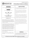
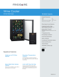
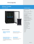
INSTRUCTIONS
®
REV. 10-11-2004
-J01449
Kit Numbers 57070-98 (primed kit)
DETACHABLE QUARTER FAIRING AND DOCKING HARDWARE KIT
General
This kit is for installation on 1988 and later XL, FXR and FXD
model motorcycles with 39 mm front forks. This kit does not fit
XL Custom or FXLR model motorcycles.
This kit must be installed with Docking Hardware Kit Part
Number 58164-96. This kit must be purchased separately from
your Harley-Davidson Dealer.
NOTE
Fork tubes may slide downward within fork brackets. If this
occurs, front fork tube extension above front fork upper bracket
will have to be readjusted according to appropriate Service
Manual procedures.
7.
Connect the right directional light as follows: Strip approx.
5/16 in. of insulation from the wires cut in step 3.
8.
Crimp solderless connectors from kit on two wires coming
from motorcycle.
9.
Split one end of the 2-conductor polarized wire from kit back
about 2 in. and strip 5/16 in. of insulation from wire ends.
See Service Parts Illustration on page 5 for a list of kit contents.
NOTE
A Service Manual for your vehicle is available from your HarleyDavidson Dealer.
Installation
1WARNING
The rider's safety depends upon the correct installation
of this kit. Use the appropriate service manual procedures. If the procedure is not within your capabilities or
you do not have the correct tools, have a HarleyDavidson dealer perform the installation. Improper
installation of this kit could result in death or serious
injury. (00333a)
NOTE
If your motorcycle has directional lights mounted on the upper
fork bracket they must be relocated to the bottom fork bracket.
Some models have front directional lights equipped with three
wires, the third black wire is a ground wire. Check to determine
how many wires are connected to the front directional lights and
follow the following procedure that applies. If directional lights
are not mounted on the upper fork bracket proceed to
“ASSEMBLING FAIRING".
Relocating Two Wire Directional Lights
10. Slide a piece of shrink tubing from kit over each of the wire
ends stripped in step 9 and crimp the wires into the
terminals installed in step 8. Make sure you connect the
silver and copper colored wires to like colored wires.
NOTE
Polarized wire is used in this application to ensure correct wiring.
One wire is silver, one is copper colored. Wire colors of spliced
wire must match wire color of original directional wire leads.
11. Cut polarized wires to the length required for connection to
the wires at the relocated directional light. Make certain
you leave enough slack in wires to allow routing the
harness along the fork tube.
12. Split remaining end of the 2-conductor polarized wire from
kit back about 2 in. and strip 5/16 in. of insulation from wire
ends.
13. Slide heat shrink tubes over the two wire end.
14. Strip 5/16 in. of insulation from wires connected to
directional light and connect like colored wires at directional
light with connectors from kit.
1.
Support motorcycle on a center stand such that front wheel
is raised slightly off the ground.
15. Slide heat shrink tubing over connectors installed in steps
10 and 14. Activate shrink tubing with heat gun or hair
dryer.
2.
Remove fork tube pinch screw from right side of lower
bracket.
16. Position harness along fork tube and secure with cable
straps.
3.
Cut wires connected to right directional light about 2 in.
away from directional light body.
17. Repeat steps 7 through 16 for left directional light.
4.
Remove fork tube pinch screw from right side of upper fork
bracket. (This is the screw that secures the right directional
light.)
5.
6.
Install right directional light on right side of lower fork
bracket using pinch screw removed in step 4. Install pinch
screw removed in step 2 into right side of upper bracket.
Tighten both pinch screws to 30-35 ft-lbs.
Repeat steps 1 through 5 to relocate left directional light.
18. Continue at “ASSEMBLING FAIRING”.
Relocating Three Wire Directional Lights
1.
Support motorcycle on a center stand such that front wheel
is raised slightly off the ground.
2.
Remove fork tube pinch screw from right side of lower
bracket.
3.
Carefully cut off 4 in. of conduit covering the wires
connected to right directional light.
1 of 6
4.
Cut the directional light wires at the following lengths from
the directional light:
i07000
Blue wire- 1-1/4 in. from directional light
Violet wire- 2-1/4 in. from directional light
Black wire- 3-1/4 in. from directional light
NOTE
The wires are cut at different lengths to stagger the butt
connectors and prevent a large bulge in the harness.
5.
Strip 5/16 in. of insulation from the cut ends of the three
wires cut in step 4.
6.
Remove fork tube pinch screw from right side of upper fork
bracket. (This is the screw that secures the right directional
light.)
7.
Install right directional light on right side of lower fork
bracket using pinch screw removed in step 6. Install pinch
screw removed in step 2 into right side of upper
bracket.Tighten both pinch screws to 30-35 ft-lbs.
8.
Repeat steps 1 through 7 to relocate left directional light.
NOTE
Fork tubes may slide downward within fork brackets. If this
occurs, front fork tube extension above front fork upper bracket
will have to be readjusted according to appropriate Service
Manual procedures.
9.
Connect right directional as follows: Crimp solderless
connectors from kit on three wires coming from motorcycle.
10. Cut a 6 in. length of wire from the black, blue and violet
wires in the kit.
11. Strip 5/16 in. of insulation from one end on each of the 6 in.
wire lengths, connect like colored wires and crimp into
connectors installed in step 9.
1
2
1
2
Figure 1. Inner view of fairing
21. Position harness along fork tube and secure with cable
straps.
22. Repeat steps 9 through 21 to connect left directional light.
23. Continue at “ASSEMBLING FAIRING”.
Assembling Fairing
1.
12. Slide shrink tubing from kit over crimped terminals. Activate
shrink tubing with heat gun or hair dryer.
13. Cut 8 in. of 5/16 in. ID conduit from conduit supplied with kit.
14. Slide 8 in. length of conduit onto three wires connected in
step11 and over existing conduit.
15. Cut three spliced-on wires to the lengths required for
connection to the wires connected to the directional light.
Make certain to leave enough slack to allow routing harness
along fork tube.
16. Slide heat shrink tubes over the three wire ends.
Gasket
Adhesive application area
See Figure 1. Attach gasket (1) to the edge of the fairing at
the headlamp opening as shown. Place the gap in the
gasket at the top of the headlamp opening, then trim the
gasket to the proper length so that the ends meet.
1WARNING
Please observe this warning when applying the adhesive in
this kit. EYE IRRITANT. BONDS SKIN IN SECONDS. CONTAINS CYANOACRYLATE ESTER. Avoid contact with skin
and eyes. In case of eye or mouth contact, hold eyelid or
mouth open and flush with water. Call physician immediately. If fingers become bonded, soak in warm soapy water.
Avoid prolonged breathing of vapors. Use with adequate
ventilation. KEEP OUT OF THE REACH OF CHILDREN.
2.
Carefully apply one to two drops of adhesive at areas
indicated (2) and to the gasket ends. Glue the ends
together. With the gasket installed on the fairing, carefully lift
the inside edge of the gasket and apply one drop of
adhesive to the gasket and non-painted surface of the
fairing as shown.
19. Slide 5/16 in conduit, installed in step 14, over all new
connections and as close to directional light as possible.
3.
Attach left and right mounting brackets (14, 15) to quarter
fairing (3) with self tapping screws (10).
20. Install a cable strap on the 5/16 in. conduit, next to
directional light, to secure conduit in position.
4.
See Figures 2. , 3 and Service Parts Illustration. Attach
springs (1) to brackets (2) as shown.
17. Strip 5/16 in. of insulation from remaining wire ends and
connect like colored wires at directional light with
connectors from kit.
18. Slide heat shrink tubing over connectors and activate shrink
tubing with heat gun or hair dryer.
-J01449
2 of 6
i06999
i06898
1
2
2
5
1
6
1
2
Spring
Bracket
4
Figure 2. Installed spring
5.
See Figure 3. Feed the large hooked end of spring (1)
through the slot in the bracket. Slide the spring until coiled
portion aligns with the 1/4" hole in bracket. Compress ends
of spring together and feed the small hooked end (2)
through the same slot that the large hooked end went
through. Insert bushings (3) into coiled ends of spring as
shown. Line up the spring and bushings with the 1/4" hole
and fasten with screw (4), washer (5) and acorn nut (6) as
shown.
6.
See Service Parts Illustration. Mount attaching brackets (6)
to outside face of brackets (14, 15) using shoulder bolt (18)
washer (20) and locknut (21). Leave assembly snug to allow
for adjustment later.
7.
Place wellnuts (16) into fairing (3) and attach headlight
cover (7) with washers (4) and screws (2).
8.
Remove the backing to the adhesive backed pads (23) and
attach them in the locations shown. Two pads are placed on
the upper corner of the fairing in the windshield recess and
two pads are placed on the inner surface of the windshield
in the bottom corners.
9.
Attach windshield (1) to fairing using the 4 gaskets (19)
along with screws (2), washers (4) and nuts (22). The
windshield can be positioned in two different locations. The
upper position allows air to pass through fairing creating a
more open feel when riding. To change positions, remove
screws and rotate the gaskets (19) to plug the unused holes
and reinstall the windshield and screws.
3
1
2
3
Large hooked end of spring
Small hooked end
Bushings
Figure 3. Rear view of installed spring
i00711
2
1
1.
2.
Clutch cable
Handlebars
Figure 4. New Clutch Cable Routing
i06938
1
2
4
Installing Quarter Fairing
NOTE
Cover gas tank and front fender before beginning installation to
prevent scratching.
1.
See Figure 4. Relocate clutch cable (1) to the inside of the
handlebars (2) as shown in illustration as follows:
a.
b.
See Figure 5. Slide rubber boot (1) off cable adjuster
(2). Adjuster is located approximately halfway along
clutch cable by the front frame downtube.
Holding cable adjuster with 1/2 inch wrench, loosen
jam nut (3) using a 9/16 inch wrench. Back jam nut
away from cable adjuster. Move adjuster toward jam
nut to introduce a large amount of freeplay at the hand
lever.
-J01449
3
1
2
3
4
Rubber boot
Cable adjuster
Jam nut
Cable end
c.
d.
Figure 5. Clutch cable adjustment
Remove small snap ring from pivot pin groove at
bottom of clutch lever bracket. Remove pivot pin and
clutch hand lever from bracket.
Reroute clutch cable to the inside of the handlebars as
shown in Figure 4 and reconnect clutch cable to clutch
lever by reversing step c.
3 of 6
e.
f.
See Figure 6. Turn cable adjuster away from jam nut
until slack is eliminated at hand lever. Pull clutch cable
ferrule away from clutch lever bracket to check free
play. Turn cable adjuster as necessary to obtain 1/16
to 1/8 inch (1.6-3.2 mm) free play (1) between end of
cable ferrule and clutch lever bracket.
i01138
1
Hold adjuster with 1/2 inch wrench. Using 9/16 inch
wrench, tighten jam nut against cable adjuster. Cover
cable adjuster mechanism with rubber boot.
2
i00716
1/16-1/8 inch
(1.6-3.2 mm)
1
1.
2.
Wireform
Chrome washer
Figure 7. Throttle Cable Attachment on all
handlebars except buckhorn-style
1.
Free play
Figure 6. Clutch Cable Adjustment
2.
1WARNING
After securing throttle cable with wireform, check that throttle control opens and closes smoothly when handlebars are
turned fully to left and right fork stops. A sticking throttle
could result in loss of control of the vehicle and possible
personal injury.
3.
4.
5.
2
See Figure 7 and Service Parts Illustration on page 6. For
handlebar styles other than buckhorn pullbacks, use
wireform (1) (item 1 on Service Parts, sheet 6) included in
hardware kit part number 58164-96 to secure throttle cables
to upper mounting clamp as shown. Place chrome washer
(2) from hardware kit (item 6 on Service Parts, sheet 6)
between wireform and mounting clamp nut.
See Service Parts Illustration on page 6. For buckhornstyle pullback handlebars, use wireform (1) included in kit
to secure throttle cables to upper fork triple clamp as
shown. Use sockethead screw (8) and washer (6)
contained in hardware kit, and place washer under
wireform.
See Service Parts Illustration. Assemble mounting
hardware for lower fairing mounting as shown. Locate
assemblies approximately 1/2 inch from lower fork triple
clamp with clamp nuts facing rear of motorcycle. Tighten
clamp nuts to 10 ft-lbs (14 Nm). Be sure the clamp does not
rotate during tightening (the mounting bushing must be
parallel to the fairing brackets). Tighten buttonhead screws
(4) to 15 ft-lbs (20 Nm).
Hook the two lower quarter fairing assembly “jaws” into the
grooves of the lower bushings then slide the upper clamp
assemblies into place until the upper bushings firmly fit into
the upper fairing "jaws".
With quarter fairing in place, tighten upper clamp nuts to 10
ft-lbs (14 Nm). Be sure the clamp does not rotate during
tightening (the mounting bushing must be parallel to the
fairing brackets).
-J01449
i00712
1
3
4
1.
2.
3.
4.
Sockethead screw, item 8 on sheet 6. Or stock if
XL Custom or FXLR models
Stock washer (Retain for re-use)
Washer (See item 6 on page 6.)
Wireform (See item 1, page 6.)
Figure 8. Throttle Cable Attachment on
Buckhorn style pullback handlebars
6.
Align fairing with headlight and tighten nuts (21) on the
adjustable brackets (6, 14, 15). When tight, verify function of
detachable feature by grabbing the fairing and pulling
forward and upward to remove. If brackets or clamps slide
or rotate during removal, realign and retighten all fasteners.
NOTE
Inspect fairing for proper adjustment in relation to the headlamp
opening. If necessary, adjust the mounting clamps up or down
for proper headlamp to fairing relationship.
7.
If front signal lights were relocated, test operation of turn
signals and running lights. If operation is not correct, verify
that the wire splices were made properly.
1WARNING
Inspect fairing upon completion of installation. Be sure fairing mounting does not restrict full left or full right movement of front fork assembly. Restricted movement could
affect handling, resulting in personal injury. If restriction
does occur, adjust fairing as needed until proper clearance
is obtained.
4 of 6
1WARNING
CAUTION
Harley-Davidson windshields are made of Lexan. Lexan is a
more durable and distortion-resistant material than other
types of motorcycle windshield material, but still requires
attention and care to maintain. Failure to maintain Lexan
properly can result in damage to the windshield. (00230a)
Check mounting hardware periodically. Never ride with
loose mounts. A loose mounting causes extra stress on all
other mounts, as well as the fairing itself, and could result
in premature failure of components allowing the fairing to
detach and startle rider. This could cause loss of control
and personal injury.
CAUTION
Do not use harsh chemicals including rain sheeting products on Harley-Davidson windshields. They can cause
dulling or hazing. If you want to use a windshield protectant on your windshield, try Harley Glaze Polish and
Sealant (00231a)
Care and Cleaning
NOTE
Sunlight reflections off of the inside curvature of a windshield
can, at certain times of the day, cause extreme heat build-up on
motorcycle instruments. Exercise care in parking. Park facing
the sun, place an opaque object over the instruments, or adjust
the windshield to avoid reflections.
CAUTION
Do not use benzine, paint thinner, gasoline or any other
type of harsh cleaner on the windshield. Doing so will damage the windshield surface. (00232a)
CAUTION
•
Do not clean Lexan® polycarbonate in hot sun or high temperature. Powdered, abrasive or alkaline cleanser will damage the windshield. Never scrape the windshield with a
razor blade or other sharp instruments because permanent
damage will result.
®
Do not use benzine, paint thinner, gasoline, lubricants
(including Armorall®), or other cleaning agents on the rubber bushings. They will damage the bushing surfaces.
NOTE
Covering the windshield with a clean, wet cloth for approximately
15 minutes before washing will make dried bug removal easier.
Service Parts
Part No. 57070-98
Date 10/04
Detachable Quarter Fairing Kits
1
sp57070-99
8,9
18
19
12
11
14,15
23
2
5
20
4
10
22
21
23
16
13
6
4
17
Item
1
2
3
4
5
6
7
8
9
10
11
Description
Windshield
Buttonhead screws (7)
Quarter Fairing (primed)
Washers (7)
Nylon bushings (4)
bracket (2)
Headlight cover
LT wireform, not shown
RT wireform
Screw, tapping (6)
Acorn nuts, 1/4-20 (2)
-J01449
7
3
2
Part No.
57074-98
982
57077-98
6276
58272-95
57073-98
57075-98
58579-96A
58580-96A
5209
94004-90T
Item
12
13
14
15
16
17
18
19
20
21
22
23
Description
Flatwashers (2)
Buttonhead screws (2)
Bracket, left, not shown
Bracket, right
Well nut (3)
Gasket, edge
Bolt, 1/4-20 carriage (4)
Gasket, trim (4)
Washer (4)
Nut, flange 1/4-20
Nut, keps #6-32 (4)
Pads, adhesive backed (4)
Part No.
6703
94426-95
57071-98
57072-98
5210
52428-99
5403B
57076-98
6424
7981
7979
57078-99
5 of 6
®
Part No. 58164-96
Service Parts
Date 10/04
Windshield Docking Hardware Kit
sp58034-3a
10
8
6
1
11
2
1
5
5
12
12
6
3
3
6
13
4
13
4
2
Item Description
Hardware kit (58164-96):
1
Wireform
2
Mounting clamp (4)
3
Bushings (4)
4
Buttonhead screw (2),
5/16-24 x 5/8 long
5
Mushroom fastener (2)
10
11
12
13
Part No.
58558-97
58124-96
67621-94
Item
6
7
8
94468-94T
58172-96
9
Description
Flatwasher, chrome (5)
(use with wireform, item 1)
Turn signal relocation kit
(not shown)
Sockethead screw,
5/16-18 x 1.25 long
Cable straps (4), not shown
Part No.
94066-90T
72389-96
3210
10006
NOTE:
Wireform location and throttle cable routing for buckhorn-style pullback handlebars.
Wireform location and throttle cable routing for handlebar styles other than buckhorn-style pullbacks.
Upper windshield mounting.
Lower windshield mounting.
-J01449
6 of 6