1
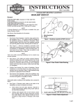
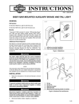
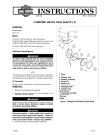
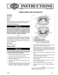
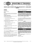
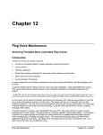
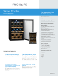
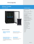
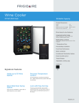
-J02826
REV. 2005-11-29
DETACHABLE WINDSHIELD AND DOCKING HARDWARE KIT
GENERAL
is01985
Kit Number
58865-03, 58880-03, 58362-03
Models
These kits fit 1984 and later FXST, FXSTB, FXSTC, and 1993
and later FXDWG model motorcycles when equipped with
passing lamps.
Table 1. Models
Kits
Contents
58865-03
Clear standard height windshield
58880-03
Smoked standard height windshield
Figure 1. New Clutch Cable Routing
2.
Kit 58362-03 contains the docking hardware required to mount
the above windshields kits.
For FXSTB Models: Proceed to Step 3.
For all except FXSTB: See Figure 1. Relocate the clutch
cable to the inside of the handlebars as follows:
a.
Locate cable adjuster halfway along clutch cable by
the front frame downtube and slide off rubber boot.
b.
Holding cable adjuster with 1/2 inch wrench, loosen
jam nut using a 9/16 inch wrench. Back jam nut away
from cable adjuster. Move adjuster toward jam nut to
introduce a large amount of free play at hand lever.
c.
Remove small snap ring from pivot pin groove at
bottom of clutch lever bracket. Remove pivot pin and
clutch hand lever from bracket. Remove anchor pin
and clutch cable eyelet from clutch hand lever.
d.
See Figure 1. Route clutch cable to the inside of the
handlebars and reconnect clutch cable to clutch lever.
e.
See Figure 2. Turn cable adjuster away from jam nut
until slack is eliminated at hand lever. Pull clutch cable
ferrule away from clutch lever bracket to check free
play. Turn cable adjuster to obtain 1/16-1/8 inch (1.63.2 mm) free play between end of cable ferrule and
clutch lever bracket.
f.
Hold adjuster with 1/2 inch wrench. Using 9/16 inch
wrench, tighten jam nut against cable adjuster. Cover
cable adjuster mechanism with rubber boot.
Additional Parts Required
NOTE
If passing lamps are being installed at the same time, you will
need the Turn Signal Relocation Kit (Harley-Davidson Part No.
68603-01) available at any Harley-Davidson dealer.
The rider's safety depends upon the correct installation
of this kit. Use the appropriate service manual procedures.
If the procedure is not within your capabilities or you do
not have the correct tools, have a Harley-Davidson dealer
perform the installation. Improper installation of this kit
could result in death or serious injury. (00333a)
NOTE
This instruction sheet references Service Manual information.
A Service Manual for your model motorcycle is required for
this installation and is available from a Harley-Davidson Dealer.
Kit Contents
See Figure 4 and Table 2, Figure 5 and Table 3.
INSTALLATION
1.
To protect against scratches, cover gas tank and front
fender before installation.
-J02826
Many Harley-Davidson® Parts & Accessories are made of plastics and metals which can be recycled.
Please dispose of materials responsibly.
1 of 5
the upper bushing. Before checking the clearance, place a
piece of masking tape against the fuel tank to eliminate the
possibility of scratching the fuel tank paint. Repeat this process
with the front forks rotated fully to the right fork stop. If clearance is less than 5/32 inch (4 mm), contact your Harley- Davidson Dealer for additional information (reference P&A Service
Bulletin P-40).
is01986
6.
Hook the two top windshield assembly "jaws" into the
grooves of the top bushings (4, in Figure 4) then slide the
lower clamp assemblies up until the lower bushings firmly
fit into the lower windshield "jaws".
7.
With windshield in place, tighten lower mounting clamp
(8) hardware by first tightening clamp nut to 10 ft-lbs (14
Nm). Be sure the clamp does not rotate during tightening
Figure 2. 1/16-1/8 inch (1.6-3.2 mm) Clutch Cable Free Play
3.
4.
5.
On FXSTB models only: Remove existing turn signal
clamps from fork tubes. Remove the original turn signal
standoff from the turn signal. The original clamp and
standoff will not be used during re-assembly.
See Figure 4. Assemble mounting hardware for lower
windshield mounting. Assemble in the following order, and
leave assembly loose:
a.
Locate the mounting hardware supplied in the docking
hardware kit.
b.
Place flatwasher (5) and bushing (4) on bolt (3) and
install on clamp.
c.
Install clamp assembly onto the fork tube with the
clamp nut forward toward the headlamp.
See Figure 5. Assemble hardware for upper windshield
mounting as shown in illustration and tighten buttonhead
screws to 15 ft-lbs (20 Nm). The spacer (1), not visible in
the illustration, fits between the retainer wire bracket (6,
7) and the upper fork triple clamp.
(NOTE: The mounting bushings must be parallel to the
windshield brackets).
8.
Remove windshield by grabbing windshield edges parallel
with center brace and firmly pulling windshield loose from
upper bushing grooves. Lift windshield assembly off of
lower bushings.
9.
Reattach brake line clamp to upper fork triple clamp.
10. If necessary, follow directions provided in Turn Signal
Relocation Kit and install the turn signals.
Improper installation of accessories or loading of cargo
can affect motorcycle stability and handling, which could
result in death or serious injury. (00455b)
Failure to provide adequate clearance between stationary
and moving parts can cause loss of control, which could
result in death or serious injury. (00378a)
is01988
NOTE
Inspect windshield upon completion of installation. Be sure
windshield mounting does not restrict full left or full right
movement of front fork assembly. Restricted movement could
affect handling, resulting in death or serious injury. If restriction
does occur, adjust windshield as needed until proper clearance
is obtained. Have experienced Harley-Davidson service personnel correct any problems before riding with this accessory
installed.
NOTE
Check mounting hardware periodically. Never ride with loose
mounts. A loose mounting causes extra stress on all other
mounts, as well as the windshield itself, and could result in
premature failure of components.
Figure 3. Measuring Clearance (looking down on docking
point from above)
NOTE
Check for proper clearance between upper bushing and fuel
tank before installing windshield as follows: See Figure 3. Turn
the front forks to the left, allowing the fork to rest against the
fork stop. Measure the clearance between the fuel tank and
the upper bushing. We recommend using the shank end of the
proper size drill bit as a feeler gauge between the fuel tank and
-J02826
CARE AND CLEANING
NOTE
Sunlight reflections off of the inside curvature of a windshield
can, at certain times of the day, cause extreme heat build-up
on motorcycle instruments. Exercise care in parking. Park
facing the sun, place an opaque object over the instruments,
or adjust the windshield to avoid reflections.
2 of 5
Harley-Davidson windshields are made of Lexan. Lexan
is a more durable and distortion-resistant material than
other types of motorcycle windshield material, but still
requires attention and care to maintain. Failure to maintain
Lexan properly can result in damage to the windshield.
(00230a)
Do not use benzine, paint thinner, gasoline or any other
type of harsh cleaner on the windshield. Doing so will
damage the windshield surface. (00232a)
Do not use harsh chemicals including rain sheeting
products on Harley-Davidson windshields.They can cause
dulling or hazing. If you want to use a windshield protectant on your windshield, try Harley Glaze Polish and
Sealant (00231a)
NOTES
-J02826
Do not clean Lexan® polycarbonate in hot sun or high temperature. Powdered, abrasive or alkaline cleanser will damage
the windshield. Never scrape the windshield with a razor blade
or other sharp instruments because permanent damage will
result.
Covering the windshield with a clean, wet cloth for about 15
minutes before washing will make dried bug removal easier.
Harley-Davidson Windshield Water Repellent Treatment Part
Number 99841-01 is approved for use on Harley-Davidson
Lexan® windshields.
3 of 5
SERVICE PARTS
is02108
1
2
5
4
6
7
4
5
3
9
8
Figure 4. Service Parts: Docking Hardware Kit
Table 2. Service Parts: Docking Hardware Kit
Item
Description (Quantity)
Part Number
1
Spacer (2) - behind bracket
58349-96
2
5/16-24 x 7/8 inch buttonhead screws (2)
94467-94T
3
Screw (2)
94468-94T
4
Bushings (4)
67621-94
5
5/16 inch chrome flat washers (4)
94066-90T
6
Left retainer wire bracket
58514-96
7
Right retainer wire bracket
58515-96
8
Mounting clamps (2)
58351-96
9
Cable ties (6)
10006
-J02826
4 of 5
is02110
17
18
1
19
12 13
5
16
11
6
14
7
2
4
14
10
3
15
15
9
8
Figure 5. Service Parts: Windshield Kit
Table 3. Service Parts: Windshield Kit
Item
1
Description (Quantity)
Part
Number
Description (Quantity)
Part
Number
10
Outer horizontal trim strip
58051-78A
Kit Number 58865-03 clear
58265-03
11
Inner horizontal trim strip
58050-78A
Kit Number 58880-03 smoked
58264-03
12
Wireform, left
58329-96
2
Panhead screws, TORX (2)
2452
13
Wireform, right
58328-96
3
Panhead screws, TORX (5)
2921
14
Horizontal tape (2)
58052-78
4
Washers (4)
58152-96
15
Vertical tape (2)
59415-03
5
Nylon bushings (4)
58272-95
16
Buttonhead screws (2)
94426-95
6
Bracket, right
58881-03
17
Acorn nuts (7)
7651
7
Bracket, left
58913-03
18
Acorn nuts, 1/4-20 (2)
94004-90T
8
Outer trim strip, right
58979-03
19
Flatwashers (2)
6703
9
Outer trim strip, left
59073-03
-J02826
Windshields
Item
5 of 5