1
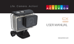
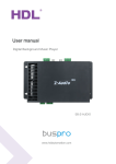
User Manual Air-condition controller SB-DN-HVAC (MAC01.331) www.hdlautomation.com User Manual SB-DN-MAC01.331 INDEX 1. Overview .......................................................................................................................................... 1 2. Main functions ................................................................................................................................ 1 3. Basic parameters ............................................................................................................................ 1 4. specifications .................................................................................................................................. 2 4.1 Dimension and specifications ………………………………………………………………………………………….2 4.2 Safety ………………………………………………………………………………………………………………………………3 5. Wiring………………………………………………………………………………………………………………………………….3 5.2 wiring diagram……………………………………………………………………………………………………………….3 5.2 connector information……………………………………………………………………………………………………4 6. Operation…………………………………………………………………………………………………………………………….4 6.1 commissioning……………………………………………………….……………………………………………………4 6.2 software configuration ....................................................................................... 5 6.2.1 Basic settings…………………………………………………………………………………………………………..5 6.2.2 Settings ……………………………………………………………………………………………………………….….5 6.2.2.1 Test the wiring ………………………………………………………………………………………………….6 6.2.2.2: Air-condition delay settings……………………………………………………………………………..7 6.2.2.3 AC model configuration…………………………………………………………………………………….7 6.2.3.3.4 VAV fan voltage settings……………………………………………………………………………..….8 6.2.3 Air-setup………………………………………………………………………………………………………………9 6.2.3.1 Operation type………………………………………………………………………………………………….9 6.2.3.2 Temperature settings………………………………………………………………………………………..9 6.2.3.3 Host settings……………………………………………………………………………………………………10 6.2.3.4 Model and statue……………………………………………………………………………………………11 6.2.4: configuration on DLP……………………………………………………………………………………………..11 6.2.4.1 Basic information…………………………………………………………………………………………….11 6.2.4.2 Test and Control………………………………………………………………………………………………12 6.2.4.3 Slave information……………………………………………………………………………………………13 6.2.4.4 Synchronous control ………………………………………………………………………………………13 6.2.4.5 Other function..……………………………………………….……………………………………………..14 7. FAQ……………………………………………………………………………….……..........16 8. NOTES ………………………………….……………….…………...………………………18 DMX Recorder – Operation Manual User Manual SB-DN-MAC01.331 1. Overview SB-DN-HVAC (MAC01.31) module designed to control centralized HVAC or FCU, through HDL control panel with air-conditioning function, depending on the preset and current temperature and with the built-in algorithm, it can smartly control the mode and fan speed. 2. Main functions It has three relays to control modes ( cooling, heating and dehumidification) Three relays to control fun speed ( low, medium and high) Built-in controlling algorithm which can control the air-conditioner smartly. Can be connected up to 4 PCS of DS18B20( Digital Temperature Sensor, supplied by HDL) One master module can control about 8 slave modules. Support online upgrading. 3. Basic parameters Electric parameters Power input BUS Power consumption Bus power supply: DC24 90mA/DC24V Maximum current per channel 2A Installation mode standard 35mm DIN Rail Mount Dimension 72x90x66(mm) Relay life 60000 Working environment Working relative humidity 0℃~45℃ Working temperature 20%~90% Storage temperature -40℃~+55℃ Storage relative humidity 10%~93% Approval Approved by CE AC controller – User Manual 1 User Manual SB-DN-MAC01.331 4. Dimension and specifications 4.1: Dimensions a) Relay 1,2,3 for mode connection b) H,M and L= AC220-240V, COM2=connect to Fan motor c) Manual control button for mode , fan speed and ( next, previous) d) LED indicator or programming button。 e) DC0-10 relay for extra fan control method, digital temperature sensor f) F,G,H,I and J are HDL interface 4.2: Safety HVAC systems draw large amounts of electricity when in use, which means that improper AC controller – User Manual 2 User Manual SB-DN-MAC01.331 installation can result in a risk of electrical fires, shocks and short circuits. Some states have specific building codes that govern HVAC systems, including their wiring. Electrical codes also apply to HVAC wiring and require electricians and builders to use wires and devices that are compliant and safe. Safety instructions we recommend to connect a proper fuse or MCB to the power input The tightening torque do not exceed 0.4Nm, Power cable require( Switch):0.75mm2 to 2.5mm2wire. Mounting position: DB Do not make wrong connection on Bus interface, it may cause a damage to the Bus interface void the rain or water into module, it will damage this devices Do not get AC220V voltage into Bus wire , it will damage all of devices in system check the type of the valve on working voltage , make sure the input voltage is matched with valve Type of FAN - check the FAN type, make sure the type is AC or 0-10V . 5. Wiring 5.1 wiring diagram The below wiring diagram must be followed strictly. AC controller – User Manual 3 User Manual SB-DN-MAC01.331 5.2: Connector info 6. Operation 6.1: commissioning Method One: 1. Run the HDL-BUS Pro Setup tool. 2. Long press the “programming button” and keep pressing it for 3 seconds until it turns to a red color. 3. On the software, click the “Address management”, and select “Modify address (when device button is pressed)” option, it will show a window like below: 4. click on “Indicate initial address”, then it will show the current subnet/device ID of this device. to modify the address, fill in the new address, and click the “Modify initial address ”Click the “+Add” button, the device will be added to “ON-line devices “list. Method two: 1- Run HDL-bus pro tool 2- Search for the online devices by clicking on search button and the device will be showed on “online device list” 6.2: software configurations Normally we need to use a HDL panel with air-conditioning function to control this module, which means in this manual both the configuration of HDL HVAC module and DLP air-condition function will be covered. 6.2.1 Basic settings This tab displays the basic information of this device. AC controller – User Manual 4 User Manual SB-DN-MAC01.331 6.2.1.1: Change the address (Subnet / Device ID) Each HDL-device has subnet and Device ID and each module’s Device ID must be unique and different from other devices on the same Bus, the subnet ID should be the same as the HDL-Bus gateway (typically the SB-DN-1IPorHDL-MBUS01IP.431). . 6.2.1.2 Remark To give a name to the module so you can recognize it from other modules. 6.2.2 Setting The setting tab is the main page to set all the configuration of this module:- AC controller – User Manual 5 User Manual SB-DN-MAC01.331 6.2.2.1 Test the wiring The wiring test ensures that every relay has been wired correctly and that the system can operate safely, so before programming an end-user panel, the relay wiring can be tested here. Steps: To test the wiring of this module: a) On the “setting” tab tick the option “model of test relay enable ”to enter the test mode. b) You can read each relays status by clicking on “read” button c) Then click on “set “to check and test each relay. 6.2.2.2 Air-condition delay settings The compressor delay helps to protect the HVAC module from several problems, so it’s better to set some delay for each compressor. 6.2.2.3 AC model configuration AC controller – User Manual 6 User Manual SB-DN-MAC01.331 6.2.2.3.1 Ac model configuration types There two different modes for the AC model settings regarding the wiring diagram:a) Normal Mode: this mode is the default mode and its correspondent to this module’s default wiring diagram, below is the normal wiring for this module:Default wiring: Relay-1=Cooling, Relay-2=Heating, Relay-3=Dehumidification. b) Complex Mode: this mode is only used when the wiring is not the default wiring so you can optimize and configure the module according to your own wiring. For example: suppose that relay#1 is heating, relay#2 is dehumidification and relay#3 is cooling, in this case we need to make some modification in the Complex mode as the below figure shows. Steps: To modify HVAC complex settings according to specific wiring a) Select Complex mode b) Double click on “HVAC setting“ table to modify the settings and change the settings in the pop-up window. Relay power restore: if this is selected, this module will recover each mode’s status before power off. P.s: this function is only assured when the mode is relay and not for HVAC as below screenshot shows. 2) Compressor protection AC controller – User Manual 7 User Manual SB-DN-MAC01.331 If this feature is selected the AC will stop working after period of time“ Compressor work time” for specified period of time “ compressor protect time “for protection and will restart working again after that period. For example: if we set the compressor time as 120minutes and Compressor protect time as 10minutes, thus after 120m of non-stop using, the compressor will stop for 10m and restart again automatically. 6.2.2.4: VAV fan voltage settings This is the DC0-10V fan speed controlling voltage settings, the speed of the fan will increase when the voltage increased and decrease with the voltage is reduced. Note: - The parameters could be different from one fan to another, so its better to contact with the manufacturer, the minimum voltage is 0V and the maximum is 10V. 6.2.3: Air setup 6.2.3.1: Operation type There are two different operation modes. AC controller – User Manual 8 User Manual SB-DN-MAC01.331 a) Fully control: when this mode is selected the ability and authority to control its self, so it can be controlled directly life I-LIFE application for IPAD, IPHONE and android. b) Slave control: when this mode is selected, the DLP has the power of controlling this module so the other devices can control the HVAC only through DLP 6.2.3.2: Temperature sensor settings This module can support up to 4 pieces of digital temperature sensors which produced by HDL and there are two ways to broadcast the temperature a) Refer to Inside sensor: this module will receive the temperature locally from HDL-digital temperature sensors ( DS18B20) which are connected to this module, this the indoor temperature . b) Refer to outside sensor: the module will receive the temperature from another module with temperature sensing function such: another HVAC module , FH module or any other HDL device with this feature. Steps: a) Select refer to outside sensor on the Air-setup tab b) Tick on any of the 4 temperature sensors and fill the subnet/device ID of the module AC controller – User Manual 9 User Manual SB-DN-MAC01.331 that the temperature will be broadcasted from. 6.2.3.3: Host settings As we mentioned above one master HVAC module can host and control about 8 slave modules, so all of those slave modules will get the modes and fan speed settings through the master module. Steps:a) Tick the option “Host Enable”to enable the function b) Select the “Slave No” C) Tick on Enable to enable the hosting function for the specified module. 6.2.3.4: model and statue This section focuses on the AC information and its modifications 6.2.3.4.1: temperature type Select one of the temperature measurements a) Celsius ( C ) b) Fahrenheit(F) AC controller – User Manual 10 User Manual SB-DN-MAC01.331 6.2.3.4.2: air-condition control information This section allows you to enable/disable some of the function depending on your needs, just uncheck any function that you want to eliminate and save. 6.2.4: configuration on DLP On the DLP, the first thing that we have to do is to make sure that the air-conditioning page has been activated. After activating the AC page, switch to DLP’s air-conditioning function page. 6.2.4.1: basic information This section shows the basic settings for controlling the HVAC module. AC controller – User Manual 11 User Manual SB-DN-MAC01.331 a) First enable the air-condition function by ticking on “enable” b) Fill in the subnet/device ID of the HVAC module c) Choose the AC type, normally choose “NEW” d) Fill in the AC No. 6.2.4.2: Test and control section a) Test: this section allows us to test the wiring of each relay and whether it’s working fine or not. You can test each relay by selecting the corresponding air-condition mode. b) Control: also in this section, you can set a desired temperature level for each mode so the HVAC will stop automatically when the desired temperature is reached. c) Unlock: you can unlock or lock the AC function, which means if this option is not selected the AC function is locked and can’t be used. 6.2.4.3: Slave information This is the host settings for DLP air-conditioning function, one master DLP panel can host about 8 slave DLP panels and the master DLP can control and monitor the slave DLPs. Application: - suppose that the kids room is on the second floor and you are on the third AC controller – User Manual 12 User Manual SB-DN-MAC01.331 floor, this function allows you to monitor the status of the DLP air-condition function page in the kid’s room without going to there. Steps: a) Select slave No. and tick on “Enable” b) Fill in the slave DLP panel’s subnet/device ID and save. c) Finally save the changes. 6.2.4.4 Synchronous control This function is DLP to DLP data transferring and sharing method, several DLPs can share the setup information each other DLP when using IR emission function to control HVAC on DLP, Up to 8 DLPs can be connected synchronously. Steps: to set up synchronous controlling between several DLP’s a) ON DLP air-conditioning function tab, select synchronous control b) Select AC NO. c) Tick on enable to activate the synchronous function d) Fill in the subnet/subnet ID of the target DLP e) Enable the IR emission function f) All above steps must be done on each DLP respectively 6.2.4.5 Other functions 1) Setup There are many useful settings in this section such as :a) Temperature model: select C or F b) Air-condition information: you can select or deselect some of the function according to the end-user requirements and needs. c) Set power saving: If this option is selected the fan will switch off automatically when the desired (target) temperature is reached. AC controller – User Manual 13 User Manual SB-DN-MAC01.331 d) Time type: select the time format (24hours or 12hours format) and date format. e) Temp range: set a temperature for each mode f) Sensor model settings: this is the temperature sensing and broadcasting settings, there are about three options:a) Refer to inside sensor: with this option, the temperature will be broadcasted locally from the respective HVAC module. b) Refer to outside sensor: the temperature will be broadcasted from outside temperature sensors, there is an average temperature broadcasting feature for outside temperature by selecting “receive broadcast “option c) Refer to average value: this is to broadcast the typical average temperature value for set of temperature sensors, instead of without showing each sensors temperature, the panel will combine all the received temperature and display their average value including the indoor temperature. 2) Control AC running Checking this option can Set the mode and speed comparing to indoor temperature and obtain the actual pattern and speed, this function should be selected as its very important for both controlling from ilife and DLP . 3) AC graphics Select the panel display photo for each mode and speed, there are some standard default photos, you can select default to use the system photos. AC controller – User Manual 14 User Manual SB-DN-MAC01.331 Steps: to setup a display photo for each key a) Select AC graphics on DLP air-conditioning function tab ,it will popup the above window and switch to content page b) Choose set up option c) Double click on the white blank area to open a picture d) Send photo and save state. P.s:- the picture format must be in P.M.P A display picture for slave DLPs can be setup here also, a) Select AC graphics on DLP air-conditioning function tab, it will popup the above window and switch to slave picture page b) Choose set-up option c) Double on each keys picture to open a photo d) Send photo and Save state. 4) IR automatic control: it’s used to control AC by sending IR code. 5) Send IR when power on: The DLP will send an IR command when its power on. AC controller – User Manual 15 User Manual SB-DN-MAC01.331 7. FAQ 7.1 MAC01.331FAQ001_HDL-BUS Q: In HDL-BUS Pro Setup Tool, I found a selection, Old or New, in DLP AC page. A: For 3-fan-speed-2-mode version, select “Old”, for 3-mode-2-fan-speed version or MAC01.331, select “New”. 7.2 MAC01.331FAQ002_HDL-BUS Q: Apart from the relay totality is different from that of SB-DN-HVAC, I can see the MAC01.331 has terminal for digital temperature sensor. A: Yes, the MAC01.331 has terminal for digital temperature sensor DS18B20, and has built-in control logic, which means once a desired temperature is set (via user panel, e.g., a DLP panel) to it, it can regulate itself and control the room temperature. This is not true for SB-DN-HAVC, the SB-DN-HAVC requires a DLP panel to be online always, because the SB-DN-HVAC has no built-in the control logic, the control logic is in DLP panel 7.3 MAC01.331FAQ003_HDL-BUS Q: To control the FCU, I can use the SB-DN-HVAC or HDL-MAC01.331, but I can also use IR (Infrared) to control it, which one is better? A: When IR control is possible, we always recommend customers to use IR (SB-IR-EM, SB-CMS-12in1 or SB-CMS-8in1) to control the FCU, because to wire the proprietary HAVC system with 3rd party controller (SB-DN-HVAC/HDL-MAC01.331), first, you may lose FCU warranty, even if you have consulted and know that you won’t lose FCU warranty, you are likely to lose some features, like, Defrost, maybe. And second, to wire the two systems (HDL-BUS system and HVAC system) together, you will have to spend some time to check the FCU manual carefully and are required some knowledge about electrical diagram. More info, HDL has a module called SB-DN-RS232N, this module can communicate 7.4 MAC01.331FAQ004_HDL-BUS Q: There are fan speed relays and there is 0-10V for fan speeds, which one to use? A: It depends on the FCU, you can refer to your FCU manual, some FCU fan speed is controlled by relays, while other FCU fan speed is controlled by 0-10V. AC controller – User Manual 16 User Manual SB-DN-MAC01.331 7.4 MAC01.331FAQ004_HDL-BUS Q: I find that when a desired temperature is reached, the fan is still running. A: If the fan speed had been set as “Low”, “Medium” or “High” but not “Auto”, the fan would run all the time even the desired temperature is reached, but no problem it is pure wind, not cold wind or hot wind. If the fan speed had been set as “Auto”, you probably forgot to enable the option “Power-saving” in HDL-BUS Pro Setup Tool. AC controller – User Manual 17 User Manual SB-DN-MAC01.331 8 NOTES AC controller – User Manual 18