1
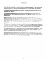
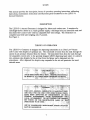
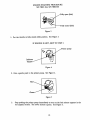
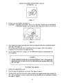
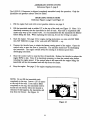
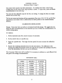
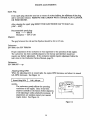
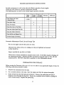
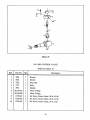
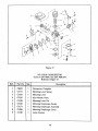
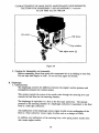
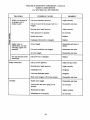
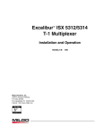
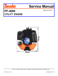
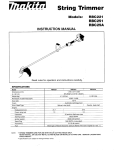
ULV
FOG GENERATOR
INSTRUCTION MANUAL AND PARTS LIST
LOWNDES ENGINEERING
COMPANY, INC.
LECO QUALITY MEANS GREATER VALUE!
WARRANTY
Lowndes Engineering Co., Inc. guarantees each new LECO Aerosol Generator to the extent: that:
"For a period of one (1) year from date of purchase, Lowndes
Eneering Co., Inc. will repiaee, free of charge, any part or parts of
the Generator found, upon examination, to be defeee in material
and/or workmanship. Such examinatibn shall be made at the LECO
factory in Valdosta, Georgia, USA or at any point designated by
Lowndes Engineering Co., Inc. The examination shall be made by a
person or persons approved by Lowndes Engineering Co., Inc.
Any part or parts returned under provisions of this Warranty shall be
returned transportation prepaid."
This is the total extent of the Warranty.
The
following are specific items and/or situations not covered by the Warranty:
Engine
The
engine is subject to the Warranty of its manufacturer.
The cost of labor in connection with
replacement or repair of defective parts.
A Generator upon which alterations have been made.
Consequential damages or contingent liabilities arising out of the failure of any
Generator to operate properly.
So
Any express, implied or statutory warranty other than set forth above.
Copyright (C) 1989, 1991
Lowndes Engineering Co., Inc.
All
fights reserved
Manufactured
by
eoCLA'RKE
159 Ni-den Ave.
POBox 72197
Roselle, IL 60172
Phone" (630) 894-2000
Fax" (630) 582-0706
ENGINEERING
TECHNOLOGIES, INC.
LECO P-1 SPECIFICATIONS
Manuasue
LECO P-l, 01/95
Revised 01/97
Engine
.Robin Two-Cycle
Blower
LECO Special Design
Dispersal Head
LECOe Design with no moving pans
Insecticide Tank
.35 Gallon
(1.32 Liters) Polyethylene,
S/N 78001 thru S/N 7800810
.66 Gallon (2.50 Liters)
S/N 7800811
up
Polyethylene,
Insecticide System
Pressufizexl by blower, no pump nary
Controls
Consists of flow control valve with four
adjustable flow rate settings
Net Weight
(Empty)
17 Pounds
Shipping Weight. (Domestic)
22 Pounds
Shipping Weight (Export)
25 Pounds
Shipping Cube
2.31 Feet
'REGISTRATION
THIS MANUAL IS FOR MY LECO AEROSOL GENERATOR
LECO MODEL P-1
SERIAL MBER
THE ABOVE INFORMATION. WHICH CANBE FOUND ON THE HANDLE
BRACE OF THE MACHINE, SHOULD BE FILLED IN. YOUR PROMPT
ATrENTION TO THIS MATI'ER WILL MAKE IT CONVENIENT FOR YOU
IN THE FWIXJRE, AS THIS INFORMATION MUST BE GIVEN WHEN
ORDERING PARTS.
FOREWORD
Every effort has been made to make this manual as complete as possible so that it will provide
maximum assistance in operating and maintaining your LECO Cold A6rosol Fog Generator.
This manual is divided generally into two sections
Illustrated Parts Section.
Operating and Maintenance Section and
Operating and Maintenance Section contains complete instructions for operating and
maintaining your LECO Cold Aerosol Fog Generator. No difficulty should be encountered in
following them.
The
Before attempting to start your unit the first time, study the complete Operating Instructions
carefully and identify all parts referred to. You will find that the operation of your LECO Cold
Aerosol Fog Generator is a simple matter of calibrating the flow rate and operating the control
valve. However, like all mechanical equipment, your unit requires a certain amount of
maintenance.
The Maintenance Instructions will enable your LECO Cold Aerosol Fog Generator to give
you
continuous and trouble-free service. It is highly recommended that some system be established
to
assure the performance of this maintenance as its importance cannot be over-emphasized.
The Illustrated Parts Section of the manual is made up of exploded views and parts lists. Every
part of the unit is illustrated and identified with a part .number. Always order parts by part
number, description and the serial number of your unit.
Although, with proper maintenance, your unit should operate indefinitely without any trouble,
there might come a time when trouble does develop. For such an occasion, complete Trouble
a
Shooting section has been prepared and included in this manual.
CONTENTS
FOREWORD
SCOPE
...........................................................
................................
DESCRIPTION
...............................
..........................................................
THEORY OF OPERATION
................................................
(S/N 78001 thru S/N 78001304)
ENGINE SPECIFICATIONS (S/N 78001305 up)
ENGINE SPECIFICATIONS
9
........................
...............................
ENGINE PREPARATION FOR OPERATION
..................................
ENGINE STARTING PROCEDURE (S/N 78001 thru S/N 78001304)
ENGINE STARTING PROCEDURE (S/N 78001305
STOPPING THE ENGINE
12
13
................................................
14
ASSEMBLING INSTRUCTIONS
OPERATING INSTRUCTIONS
CONTROL VALVE
up)
10
...........................................
14
............................................
15
.....................................................
CALIBRATING INSTRUCHqONS
15
...........................................
15
CONVERSION TABI.I:
..................................................
ENGINE ADJUSTMENTS
16
ENGINE MAINTENANCE INSTRUCTIONS
17
PREPARATION FOR STORAGE
17
CONTENTS ILLUSTRATED PARTS BREAKDOWN SECTION
18
IIUSTRATED PARTS BREAKDOWN
19
ENGINE PARTS
35
CARBURETOR SERV/ MANUAL (S/N 78001 thru S/N
78001304)
TROUBLE SHOOTING CHECKLIST (S/N 78001 thru S/N 78001304)
CARBURETOR SERVICE MrUAL (S/N 78001305--- up)
53
LECO P1 TROUBLE SHOOTING CHECKLIST
67
62
65
Figure
6
1
SCOPE
This manual
provides the description, theory of operation, operating instructions, calibrating
instructions, maintenance instructions and illustrated parts breakdown for the LECO P-1
Aerosol Generator.
DESCRIPTION
The LECO P-1 Aerosol Generator is designed for indoor and outdoor use. It consists of a
centrifugal blower driven by a 2-cycle gasoline engine, a discharge head, an insecticide tank and
insecticide flow control valve with four adjustable flow rate settings. The Generator is a
complete hand held unit weighing only 17 pounds.
See Figure 1.
THEORY OF OPERATION
The LECO P-1 Generator is designed for dispersing insecticides at an Ultra Low Volume
(ULV) rate with droplets of optimum size. The insecticide is forced from the tank through the
system by air pressure obtained from the blower. The insecticide flows from the tank through
the adjustable control valve to the specially designed LECO dispersing head where it is sheared
into optimum size droplets, by the air blast from the blower and is dispersed into the
atmosphere. After dispersal the droplets stay suspended in the air and penetrate the insect
infested areas.
Throttle
Engine
Control
Valve
Carburetor
Recoil
Start Knob
Stop
Button
Fuel-Off
Mixture Tank
Formulation
Tank
Figure 2
8
ENGINE SPECIFICATIONS
S/N 78001 thru S/N 78001304
Engine Type:
Displacement:
Robin Two-Cycle
Fuel Tank:
22.5
cc
Spark Plug:
1.37
cu.
0.7 Liter
NGK-
Champion CJ4, CJ6
Spark Plug Gap:
0.6/0.7 mm
in.
Starter:
Auto Rewind
Carburetor:
All Position-
Lubrication:
Fuel-Oil Mix between 15 and to I for the ftrst 20 hours.
Fuel-Off Mix between 20 and 25 to 1 thereafter.
Engine Type:
Displacement:
Diaphragm Type
20
ENGINE SPECIFICATIONS
S/N 78001305 up
Robin Two-Cycle
Fuel Tank:
2.2 c
Spark Plug:
1.35
cu.
---BM7A
NGK
0.6 Liter
'---B/f7/
Champion CJ4, CJ6
Spark Plug Gap:
0.6/0.7 mm
in.
Starter:
Auto Rewind
Carburetor:
All Position
Lubrication:
Fuel-Oil Mix between 15 and 20 to 1 for the first 20 hours.
Fuel-Off Mix between 20 and 25 to 1 thereafter.
Diaphragm Type
ENGINE PREPARATION FOR OPERATION
Fuel and Oil Mixture
Inspect the fuel tank and fill with clean, flesh fuel of the proper mixture.
This engine
requires a mixture of gasoline of between 20 and 25 pans gasoline to 1 part oil (1 gal.
gasoline., to 6 oz. oil) of regular leaded gasoline. For the first twenty hours, use the mixing
ratio
ofbetween 15 and 20 to
1.
DO NOT USE BIA OIL.
DO NOT MIX GASOLINE AND OIL DIRECFLY IN THE ENGINE FUEL TANK.
IMPORTANT: Failure to follow proper fuel mix instructions could result in serious damage
to the engine.
CAUTION
When preparing fuel mixture, mix only the amount needed for the job you are to do.
Do not use fuel mixture that has been stored longer than two (2) months. Fuel mixture
stored longer than this will cause hard starting and poor performance. If fuel mix has
been stored longer than this time it should be removed and filled with fresh mixture.
a
....
_..'..
CAUTION! NEVER flll the fuel tank to the inlet port level.
NEVER add fuel to the tank in a closed unventilated area.
DO NOT add fuel to this unit near an open fire or spark.
BE SURE to wipe off spilled fuel before attempting to start the
DO NOT attempt to refuel an extremely hot engine.
engine.
ENGINE STARTING PROCEDURE
S/N 78001 thnl S/N 78001304
Fully open (fast)
Fully closed (idle)
Figure 3
1. Put the throttle in fully closed
(idle) position.
See Figure 3.
IF ENGINE IS HOT, SKIP TO STEP 5.
Primer pump
Indicator
window
Figure 4
2. Give
a
.gentle push to the primer pump.
See
Figure 4.
Red
Figure 5
Stop pushing the primer pump immediately as soon as the fuel mixture appears in the
red (upper) section. The lower section is green. See Figure 5.
10
ENGINE STARTING PROCEDURE, continued
S/N 78001 thru S/N 78001304
Partly open
position
Stop
button
Figure 6
Depress the throttle lever completely, push the stop button and take your hand off of lever.
The stop button will lock the throttle lever in partly open position. See Figure 6.
Figure 7
5.
Pull the recoil start briskly. See Figure 7.
CAUTION:
Gradually return handle.
Do not let it snap back. Pull the rope in the direction
of the starter rotation. Do not pull the starter rope all the way out of the drum.
Let the engine warm up by running it at a low RPM
two minutes.
(slow speed) for approximately one or
CALON
NEVER OPERATE THE ENGINE AT HIGH RPM WITHOUT LOAD. With throule fltlly
opened and no load, the engine rpm will be very high which can have an adverse effect on the
life of the engine.
.....,
<,.
<,
:i. -,,;--.
II
5----.::,,..
ENGINE STARTING PROCEDURE
S/N 78001305 up
Fully open (fast)
Fully closed (idle)
Figure 8
1.
Put the throttle in
fully closed (idle) position.
See Figure 8.
Figure 9
Push the primer button to feed the fuel to the carburetor until fuel overflows from the
carburetor. See Figure 9.
Figure 10
3. Close the choke lever. If the engine is warm or the ambient temperature is
choke lever half-way, or keep it open fully.
If the engine is cold, or the ambient temperature is
choke lever. See Figure 10.
12
high, dose the
low, close the
ENGINE STARTING PROCEDURE, continued
S/N 78001305 up
Figure 11
Pull the recoil start briskly. See Figure 11.
CAUTION: Gradually return handle. Do not let it snap back. Pull the rope in the direction
of the starter rotation. Do not pull the starter rope all the way out of the drum.
Figure 12
St
After starting the engine, gradually open choke by turning the choke lever and finally keep it
open fully. See Figure 12.
Do not fully open the choke lever immediately when the engine is cold or the ambient
temperature is low, because the engine may stop.
Let the engine warm up by running it at a low RPM (slow speed) for approximately one
or two minutes.
NEVER. OPERATE THE ENGINE AT HIGH RPM wrIOUT LOAD. With throttle fully
opened and no load, the engine rpm will be very high which can have an adverse effect on the
life of e engine.
STOPPING THE ENGINE
lo
Reduce the engine RPM to idle.
Stop the engine by pushing the stop button. See Figure 2, page 8.
Pull the recoil start knob slowly and return the knob to its original position when resistance is
felt. This is necessary to prevent outside moist air from intruding into the combustion chamber.
See Figure 2, page 8.
13
ASSEMBLING INSTRUCFIONS
Reference Figure 2, page 8
The IFCO P-1 Generator is shipped completely assembled ready for operation.
insecticide and gasoline mixture need be added.
Only the
OPERATING INSTRUCTIONS
Reference Figure 2, page 8 and Figure 13
1.
Fill the
engine fuel tank with correct gasoline mixture, see page 9.
Fill the insecticide tank to within 1/2" to the top of the tank, see Figure 13. Note: It is
absolutely necessary that the insecticide be free of trash. Any trash or suspended solid
matter may stop up the control valve. It is recommended that the insecticide be filtered
before filling the tank. When replacing the tank cap, be sure the O-ring is in place.
engine.
See page 10 for engine starting instructions on units with S/N 78001
ttm S/N 78001304 or page 12 for units with S/N 78001305 up.
Start the
Depress the throttle lever to obtain the fastest running speed of the engine. Open the
control valve to start the flow of insecticide. The machine should now be discharging
the insecticide. The engine should always be running at its fastest speed when
discharging insecticide.
So
Close the control valve to stop the flow of insecticide. Release the throttle to reduce the
engine RPM to idle. Note: It is absolutely necessary to close the control valve before
reducing the engine speed. If the control valve is left open with the engine idling, the
insecticide will not be atomized and will drip from the nozzle.
6.
Stop the engine.
See page 13 for engine
stopping instructions.
NOTE: Do not fill the insecticide tank
completely to the top. Leave a 1/2" air space
at the top of the tank. If the tank is filled
completely to the top, the insecticide will be
forced into the blower when the throttle is
released. If this happens the insecticide will
drip from the blower. See Figure 13.
14
CONTROL VALVE
Reference Figure 2, page 8
The control valve requires very little maintenance. It is staiess steel with a viton O-ring.
Looking down on the control valve, fully clockwise is closed. To open valve, rotate the handle
counterclockwise to set screw stop.
The valve has four adjustable stops for the flow rate setting, To
relocate the set screw stop.
change the flow rate simply
The four set screw stop locations will give approximate flow rates of 1/4, 1/2, 3/4, and full flow
respectively as the control valve is rotated from the closed position to the counterclockwise
direction.
CALIBRATING INSTRUCTIONS
It has never been our policy to recommend insecticide dosage. We suggest that you
follow the label recommendation on the insecticide you use or follow the recommendation of a
reliable testing agency.
Dosage:
To Cagbrate:
1. Fill the insecticide tank with
2. Set the control valve at
a
Spray fora specific time.
a
known measure of insecticide.
specific stop.
The
longer this time period, the more accurate the cah'bration
will be.
4 Remove the remaining insecticide from the tank and measure. The difference in the
starting and ending measurement will be the usage for the specific time spraying took place.
From this information, the flow rate can be determined.
The Conversion Table below will be helpful if it is necessary to calibrate in
that given in the dosage recommendation.
CONVERSION TABLE
TO OBTAIN
Ft. Oz. / Mira
Cal./Hr.
F1. Oz. / Min.
ML / Min.
Gal. / Hr.
02.133300
FL / Min.
Gal./Hr.
63.081313130
M1. / Min.
FL Oz. / Min.
00.015852
15
Gal./Hr.
a
unit different from
Spark Plug
If the spark plug electrode area has an excess of carbon buildup, the efficiency of the plug
will be seriously reduced. REMOVE THE CARBON WITH A SPARK PLUG CLEANER
OR WIRE BRUSH.
cleaning the spark plug RESET THE'EleCTRODE GAP TO 0.6/0.7 mm
(.024" .028").
After
spark plug:
BM7A
Champion CJ4 or CJ6
Recommended
NGK
Magneto
The gap between the coil and the flywheel should be 0.4 to 0.5
mm.
Carburetor
S/N 78001 thru S/N 78001304
Proper adjustment of the carburetor is very important to the operation of this engine,
The carburetor has been carefully adjusted at the factory and therefore should not
require any further adjustment. If the carburetor should require adjustment follow the
instrction in the Carburetor Service Manual, page 53.
Carburetor
S/N 78001305
up
Adjusting Idling RPM
When. the adjusting screw is turned right, the engine RPM increases, and when it is ttirned
left, RPM decreases. See Figure 14.
Normal
Idling RPM
3100 *. 100 rpm
NOTE:
The carburetor greatly affects the operating
conditions of the engine. Since it has been
adjusted carefully at the factory before shipment,
avoid adjusting it unless absolutely necessary. If
adjustments are needed, contact your nearest
engine dealer. See Figure 14.
ADJUSTING
SCREW
Figure
16
14
ENGINE MAINTENANCE INSTRUCTIONS
Periodic maintenance is vital to the safe and efficient operation of your engine.
Cheek the table below for periodic maintenance intervals.
The following chart is based on the normal engine operation schedule.
8 hours
(daily)
Clean Engine and Check
Bolts and Nuts.
o
50 hours
200 hours
(weekly)
(monthly)
500 hours
1000 hours
(dany)
Clean Spark Plugs.
Clean Air Cleaner.
Clean Fuel Cock or Fuel Filter
Clean and Adjust Spark Plug Gap.
Clean "and Adjust Carburetor.
Clean Muffler and Exhaust Port.
:Overhaul Engine if Necsary.
Preventive Maintenance Check List and Storage Tips
Be
sure
the
engine and all other parts are clean.
Check all nuts, bolts, screws, etc.
as they should be.
making sure they are tightened and secured
Inspect carefully for any fuel or oil leaks.
Check the air cleaner assembly for excessive dust or dirt. If the filter requires cleaning, use
the following procedure. Remove the filter and wash in soap and water or blow off with
compressed air. DO NOT clean filter in gasoline-or other inflammable solvent.
PREPARATION FOR STORAGE
Before storing the Generator after use or if it is to be idle for any appreciable length of time, the
following preparations should be made:
1.
2.
3.
Remove the insecticide from the tank.
Put a suitable solvent in the tank. Start the engine and flush the system thoroughly.
Drain all fuel from the fuel tank and carburetor. Remove the spark plug and
pour a
teaspoon of oil through the plug hole. Rotate the crankshaft several times by pulling
the
starter handle slowly. Replace the spark plug.
17
CONTENTS- IIJ.USTRATED PARTS BREAKDOW SECTION
ILLUSTRATED PARTS BREAKDOWN
.....................................................
COMPLEI [;NIT (S/N 78001 thru S/N 7800810)
...............................................
COMPLETE UNIT (S/N 7800811 up)
......................................................
NO. 7562 BEARING SUPPORT
............................................................
NO. 7581 BLOWER .....................................................................
NO. 7618 NOZZLR HEAD ASSEMBLY (S/N 78001 thnl S/N 7800909)
..............................
NO. 8629 NOT.ZI.F. HEAD ASSEMBLY ($/N 710 thnl 78002063)
...............................
NO. 30327 NOZTI. HEAD ASSEMBLY (S/N 78002064--- up)
..................................
NO. 7706 INSECTICIDE TANK ASSEMBLY (S/N 78001
S/N 7N10810)
..........................
NO. 8332 INSECTICIDE TANK ASSEMBLY (S/N 7N)0811 thin S/N 78001936)
........................
NO. 310"/2 INSECTICIDE TANK ASSEMBLY (S/N 78001937-o up)
NO. 7602 CONTROL VALVE
ENGINE PARTS
.......................................................................
NO. 912014301 ENGINE (S/N 78001 thin S/N 780920)
...........................................
NO. 91201 ENGINE (S/IN 781Xt21 thnl $/N 78001304)
............................................
NO. 91460 ENGINE (S/N 78001305--. up)
....................................................
NO. 128103 CARBURETOR (S/N 78001
S/N 78001304)
.......................................
NO. 30065 CARBURETOR, and AIR CLEANER ASSEMBLY (S/N 78001305 --up)
....................
18
9
21
25
27
29
30
31
31A
32
33
33A
35
37
41
45
48
51
ILLUSTRATED PARTS BREAKDOWN
SECTION
BE-IISURE-....TO" ORDER
;RERLA
CEMENT:.,-PAR TS BY
I::NUBERI'ND SERiAL
!II:MBER OF' YOUR UNIT. '":
Procedure for
II
.'
determining correct part number and description of individual parts.
Refer to the complete unit breakdown illustration
on pages 21, 22 and pages 25, 26.
If the individual part is shown
obtained from the parts list.
on
the
on
page 20 and page 24 and the parts list
illustration, the part number and description can be
If the part is a component of an assembly, the location of the assembly breakdown can be
obtained from the parts list. This assembly breakdown will identify the individual part.
NOTE: If there is a reference to serial numbers please take this into consideration.
19
2O
COMPLETE UNIT
S/N 78001 thru S/N 7800810
Reference
Ref.
Part No.
1
2
3
4
5
6
7
8
9
10
11
12
13
14
15
16
17
18
6710-010
6712-008
7566
7570
7574
7581
7582
7602
7607
7608
7609
7610
7618
7619
7706
7724
7850
90396
90400
91201-001
191201
20
21
22
23
24
25
26
27
28
91202
91203
91204
91205
91206
91208
91209
91228
1109-001
Figure 15
Description
1
1
1
1
1
1
1
1
1
1
1
1
1
2
1
2
1
1
1
Nylon Tube, 1/40D x 10 Inches
Nylon Tube, 3/80D x 8 Inches
Adaptor Base
Flange Ring
Handle Bar
Blower (See Page 29 for Parts Breakdown)
Support Bar
Control Valve (See Page 34 for Parts Breakdown)
Base
Column
Channel Bracket
Handle Brace
Nozzle Head Assembly (See Page 30 for Pans Breakdown)
Washer, 11/32 x 1-1/8 x 1/8
Insecticide Tank Assembly (See Page 32 for Parts Breakdown)
Strap
Tank and Column Assembly
Male Elbow, 1/4 Tube x 1/4 Pipe
1/4 Nylon Ferrule Nut
Two-Cycle Engine (Used on S/N 78001 thru S/N 780020)
(See Page 37 for Parts Breakdown)
Two-Cycle Engine (Used on S/N 780021 thin S/N 7800810)
(See Page 41 for Parts Breakdown)
Throttle Lever Assembly
Throttle Wire
Shoulder Strap
Metric Cap Screw, Socket Head, 5MM x 0.8 Pitch x 24MM Long
Metric Cap Screw, Socket Head, 6MM x 1.0 Pitch x 120MM Long
Tapered Handle
Black Fin Grip
Metric Nut, 5MM x 0.8 Pitch
Washer, SAlE No. 10
21
COMPLETE UNIT, Continued
S/N 78001 thru S/N 7800810
Reference Figure 15
Ref.
Description
Part No.
1112-001
1200-071
1200-091
1201-091
1201-101
1248-i31
1278-071
1340-010
1340-014
1680-071
1680-111
2278-091
Washer, SAE 5/16
Cap Screw, Hex, 1/4-20 x 1/2
Cap Screw, Hex, 1/4-20 x 5/8
Cap Screw, Hex, 5/16-18 x 5/8
Cap Screw, Hex, 5/16-18 x 3/4
Nut, Nylok Hx, 1/4-20
Set Screw, Socket Head, 10-24 x 1/2
Lockwasher, Split, No. 10
Lockwasher, Split, 5/16
Machine Screw, P/Pan, 10-24 x 1/2
Machine Screw, P/Pan, 10-24 x 7/8
Machine Screw, Hex, 10-24 x 5/8
22
BE..SURE.. .TO.-
ORDER
REPLACEMENT PARRS BY
PART NUMBER AND SERIAL
NUMBER OF..YO UR UNIT.
23
.__J
o/
COMPLETE UNIT
S/N 7800811 ---up
Reference Figure 16
Description
Part No.
6710-017
6712-008
31071
7566
7570
7574
7581
7582
7602
7967
7966
7609
7610
7618
30327
7619
8332
Nylon Tube, 1/40D x 17 Inches
Nylon Tube, 3/80D x 8 Inches
(Used on S/N 78001 thru S/N 78001936)
Drop Pipe and Filter (Component of 31072 Assembly, Item 15)
(Used on S/N 78001937--- up)
Adaptor Base
Flange Ring
Handle Bar
Blower (See Page 29 for Parts Breakdown)
Support Bar
Control Valve (See Page 34 for Parts Breakdown)
Base
Column
Channel Bracket
Handle Brace
Nozzle Head Assembly (Used on S/N 78001 thru S/N 7800909)
(See Page 30 for Parts Breakdown)
Nozzle Head Assembly (Used on S/N 7800910 thru S/N 78002063)
(See Page 31 for Parts Breakdown)
Nozzle Head Assembly (Used on S/N 78002064-- up)
(See page 31A for Parts Breakdown)
Washer, 11/32 x 1-1/8 x 1/8
Insecticide Tank Assembly
(Used on S/N 7800811 thru
(See Page 33 for Parts Breakdown)
Insecticide Tank Assembly (Used on S/N 78001937--- up)
(See Page 33A for Parts Breakdown)
S/N 78001936)
31072
8628
91308
90396
90400
91201
91460
Bracket
Vibration Mount
Elbow, 1/4 Tube x 1/4 Pipe
1/4 Nylon Ferrule Nut
Two-Cycle Engine (Used on S/N 7800811 thru S/N 78001304)
(See Page 41 for Parts Breakdown)
Two-Cycle Engine (Used on S/N 78001305 up)
(See Page 45 for Parts Breakdown)
Male
25
COMPLETE
UNIT, Continued
S/N 7800811---up
Reference
Ref.
Figure 16
Description
Part No.
91202
91203
91204
91205
91206
91208
91209
91228
1109-001
1112-001
1200-071
1200-091
1201-091
1201-101
1248-131
1278-071
1340-010
1340-014
1680-071
1680-111
2278-091
1200-161
1111-004
Throttle Lever
Throttle Wire
Assembly
Shoulder Strap
Metric Cap Screw, Socket Head, 5MM x 0.8 Pitch x 24MM Long
Metric Cap Screw, Socket Head, 6MM x 1.0 Pitch x 120MM Long
Tapered Handle
Black Fin Grip
Metric Nut, 5MM x 0.8 Pitch
Washer, SAlE No. 10
Washer, SAE 5/16
Cap Screw,Hex, 1/4-20 x 1/2
Cap Screw, Hex, 1/4-20 x 5/8
Cap Screw, Hex, 5/16 x 5/8
Cap Screw, Hex, 5/16 x 3/4
Nut, Nylok Hex, 1/4-20
Set Screw, Socket Head, 10-24 x 1/2
Lockwasher, Sprit, No. 10
Lockwasher, Sprit, 5/16
Machine Screw, P/Pan, 10-24 x 1/2
Machine Screw, P/Pan, 10-24 x 7/8
Machine Screw, Hex, 10-24 x 5/8
Cap Screw, Hex, 1/4-20 x 1-1/2
Washer, USS 1/4
26
Figure 17
NO. 7562 BEARING SUPPORT
Reference Figure 17
Ref.
1
2
3
4
5
Description
Part No.
6723
7621
90520
90958
1680-071
1
1
1
1
4
Beadng Hub
Bearing Support Disc
Ball Bearing
Retaining Ring
Machine Screw, P/Pan Head,
27
10-24 x 1/2
/'
/'
/'
NO. 7581 BLOWER
Reference
Ref.
Part No.
Qty.
1
2
3
4
5
6
7
8
9
10
11
12
13
14
15
16
17
7559
7560
7562
7565
7567
7568
7569
7571
7572
7573
7588
7599
7601
7606
7615
1109-001
1241-192
3
2
1
1
1
1
1
1
5
2
1
1
1
1
3
3
1
Figure 18
Description
Fan
Baffle
Bearing Support (See Page 27 for Parts Breakdown)
Back Plate
Long Back Section
Long Center Section
Front Section
Shaft
Washer
Spacer
Back Disc
Washer
Short Back Section
Short Center Section
Tie Bolt
Washer, SAE No. 10
Nut, Hex, Jam, 5/8-18
29
Figure 19
NO. 7618 NOZZLE HEAD ASSEMBLY
Used on S/N 78001 thru S/N 7800909
Reference Figure 19
Ref.
Part No.
Qty.
1
2
3
7616
7617
7622
7695
1907-072
1
1
1
1
11
4
5
Description
(for replacement, order 8664 Nozfle, shown on page 31)
Spreader Ring
Baffle Assembly
Body (for replacement, order 8701 Body Replacement Kit)
No.le
Machine Screw,
S.S., P/Flat, 10-32 x 1/2
P/N 8701 Body Replacement Kit consists of:
(1) 8664 Nozzle (shown on page 31)
(1) 8671 Body (shown on page 31)
(1) 91310-014 Viton O-Ring (shown on page 31)
30
Figure 20
NO. 8629 NOZZLE HEAD ASSEMBLY
Used on S/N 7800910 thru S/N 78002063
Reference Figure 20
Qty.._._.L
Ref.
Part No.
1
2
3
4
5
6
7
8664
7617
8527
8671
1907-072
1907-112
1
91310-014
1
Description
Nozzle
Spreader Ring
Baffle Assembly
Body
Machine Screw, S.S., P/Flat,
Machine Screw,
Viton O-Ring
S.S., P/Flat,
3!
10-32 x 1/2
10-32 x 7/8
Figure 20A
NO. 30327 NOZZLE HEAD ASSEMBLY
Used on S/N 78002064--- up
Reference Figure 20A
Ref.
Part No.
Qty.
1
2
3
4
5
6
7
30548
30546
30316
30326
1907-072
1907-112
91310-014
1
1
1
7
4
1
Description
Nozzle
Spreader Ring
Baffle Assembly
Body
Machine Screw, S.S., P/Flat,
Machine Screw, S.S.,
Viton O-Ring
P/lat,
10-32 x 1/2
10-32 x 7/8
Figure 21
NO. 7706 INSECTICIDE TANK ASSEMBLY
Used on S/N 78001 thru S/N 7800810
Reference Figure 21
Ref.
1
2
3
4
Part No.
7590
7699*
7873
90396
90400
90500*
90443
90542
90994
91310-218
Qty.
1
1
1
1
1
Description
Insecticide Tank
Filter Screen
Filter Elbow
Male Elbow, 1/4 Tube x 1/4 Pipe
1/4 Nylon Ferrule Nut
Male Elbow, 3/8 Tube x 1/4 Pipe
3/8 Nylon Ferrule Nut
1
1/4 Nylon Pipe Plug
1
Tank Cap
Viton O-Ring
*Note: Not available
individually.
Available assembled in Item 3.
4
Figure 22A
NO. 31072 INSECTICIDE TANK ASSEMBLY
Used on S/N 78001937---up
Reference Figure 22A
Ref.
1
2
3
4
5
6
Part No.
7963
31071
90443
90396
90400
90542
90994
91310-218
Qty.
1
1
1
1
1
1
Description
Insecticide Tank
Drop Pipe and Filter
3/8 Nylon Ferrule Nut
Male Elbow, 1/4 Tube x 1/4 Pipe
1/4 Nylon Ferrule Nut
1/4 Nylon Pipe Plug
Tank Cap
Viton O-Ring
33A
5
Figure 22
NO. 8332 INSECTICIDE TANK ASSEMBLY
Used on S/N 7800811 thru S/N 78001936
Reference Figure 22
Ref.
Part No.
1
2
7963
8339
90443
90396
90400
90542
90994
91310-218
3
4
5
6
Qty_. ._.2.
1
1
1
1
1
1
Description
Insecticide Tank
Drop Pipe and Filter
3]8 Nylon Ferrule Nut
Male Elbow, 1/4 Tube x 1/4 Pipe
1/4 Nylon Ferrule Nut
1/4 Nylon Pipe Plug
Tank Cap
Viton O-Ring
33
7"\
8
2
Figure 23
NO. 7602 CONTROL VALVE
Reference Figure 23
Ref.
Part No.
Qty.
1
2
3
4
5
6
7
8
9
10
7604
7605
7726
7727
7872
91310-012
1
1
1
1
.1
1
1
.1
1
1
91310-009
1278-021
1278-022
1278-051
Description
Bonnet
Needle
Stop Disc
Body
Handle
Viton O-Ring
Viton O-Ring
Set Screw, Socket Head, 10-24 x 3/16
Set Screw, Socket Head, 10-32 x 3/16
Set Screw, Socket Head, 10-24 x 3/8
34
Used
Ref.
1
2
3
4
6
7
8
9
10
11
12
3
14
15
16
17
18
19
20
21
22
23
24
25
26
27
28
29
30
31
32
NO. 91201-001 ENGINE
on S/N 78001 thru S/N 780020
Reference Figure 24
Description
Part No.
C1001
C1002
C1003
C1004
C8046
C8047
C1007
C1008
C8048
C1011
C1012
C1013
C1014
C1015
C3027
C1018
C1020
C1021
C1721
C1023
C1024
C1025
C1605
C3028
C3029
C1646
C8049
C1642
C1031
C1655
C8050
C1657
1
2
2
1
1
1
1
1
1
1
1
1
2
2
1
1
1
1
1
1
1
1
1
1
1
1
2
1
1
1
1
1
Crank Case (Includes Items 2,
Oil Seal
Ball Bearing
Crank Case Packing
3, .4)
Cylinder
Cylinder Cover
Spark Plug
Cylinder Packing
Crank Shaft
Piston
Needle Bearing
Piston Pin
Piston Ring
Clip
Recoil Starter
Starter Knob
(Includes Items 16 thru 23 and Item 64)
Spiral Spring
Starter Rope
Reel
Ratchet
Friction Spring
Friction Plate
Return Spring
Muffler Assembly
Muffler Cover
Muffler Gasket
Screw, Pan Head
Fuel Pump Assembly
Hose
Clamp
Fuel Tank
Fuel Tank Cap
Rubber Tube
37
(Includes Item 29)
NO. 91201-001 ENGINE, Continued
Used on S/N 78001 thru S/N 780020
Reference Figure 24
Ref.
33
34
35
36
37
38
39
40
41
42
43
44
45
46
47
48
49
50
51
52
53
54
55
56
57
58
60
61
62
63
65
Part No.
C1035
C1036
C3030
C1660
C3031
C1658
C8051
C8052
C8053
C1277
C8054
C1051
C1440
C3032
C8055
C8056
C8057
C8058
C8059
C3035
C1425
C1659
Cl183
C1428
C1429
C1286
C1297
C1298
C1706
C1702
C1442
C1074
C1076
Description
Qty.
1
1
Weight
1
2
3
1
1
1
1
2
Pipe
Spacer
Spacer
Ring
Magneto (Includes Items 40 and 41)
Flywheel
Ignition Coil
1
1
1
1
1
1
1
1
1
3
1
2
1
3
11
4
2
3
2
1
7
4
Felt
Fuel
Washer
Grommet
Plug Cap
Spring Washer, Left
Nut, Left
Heat Insulator
Heat Insulator Packing, Carburetor
Heat Insulator Packing
Stop Button
Label
Label, Caution
Bolt, Cross Recessed
Filter
Washer
Washer
Washer
Spring Washer
Screw
Screw
Screw
Screw
Screw
Screw
Screw
38
NO. 91201-001 ENGINE, Continued
Used on S/N 78001 thru S/N 780020
Reference Figure 24
Ref.
67
68
69
70
71
72
73
74
89
98
Part No.
C1077
C1078
C8103
91241
91242
91243
91244
91245
91246
91247
Qty.
1
1
1
2
2
2
2
2
2
2
Description
Woodruff Key
Steel Ball
Carburetor (See Page 48 for Parts
Washer
Washer
Screw
Washer
Screw
Washer
Screw
39
Breakdown)
Used
Ref.
1
2
3
4
5
6
7
8
9
10
11
12
13
14
15
16
17
18
19
2O
21
22
23
24
25
26
27
29
3O
31
32
34
on
NO. 91201 ENGINE
S/N 780021 thru S/N 78001304
Reference Figure 25
Description
Part No.
C1001
C1002
C1003
C1004
C8046
C8047
C1007
C1008
C8153
C1011
C1012
C8154
C1014
C1015
C3027
C1018
C1020
C1021
C1717
C1023
C1024
C1025
C1605
C3028
C3029
C1646
C1223
C3114
C1655
C8050
C3111
C3112
1
2
2
1
Crank Case Complete
Oil Seal
Ball Bearing
Crank Case Packing
1
1
1
Cylinder
Cylinder Cover
Spark Plug
Cylinder Packing
Crank Shaft Complete
1
1
1
1
1
2
2
1
1
1
1
1
1
1
1
1
1
1
1
2
3
1
1
1
1
(Includes Items 2, 3, 4)
Piston
Needle Bearing
Piston Pin
Piston Ring
Clip
Recoil Starter Complete
Starter Knob
(Includes Items 16 thru 23, 62)
Spiral Spring
Starter Rope
Reel
Ratchet
Friction Spring
Friction Plate
Return Spring
Muffler Assembly
Muffler Cover
Muffler Gasket
Screw, Socket Head
Hose Clamp
Fuel Tank
Fuel Tank
Cap Complete
Rubber Tube
Filter
41
NO. 91201 ENGINE, Continued
Used on S/N 780021 thru S/N 78001304
Reference Figure 25
RcL
36
37
38
40
41
42
43
45
47
49
50
51
52
53
54
55
56
57
58
59
60
61
62
63
67
Description
Part No.
C3115
C3113
C1699
C8102
C8139
C8053
C8054
C1051
C1440
C1278
C8132
C3122
C8131
C8155
.C8059
C1653
C1425
C3123
C1428
C1429
C1286
C8156
C3307
C8157
C8158
C1442
C3152
C1077
C8159
C8133
Cl113
2
1
1
1
1
1
1
1
1
1
1
1
1
1
1
1
2
1
1
3
3
2
2
3
2
1
4
4
1
3
2
2
Pipe
Connector, Fuel
Spacer
Magneto Complete (Includes 41, 42)
Flywheel
Ignition Coil
Fuel
Grommet
Plug Cap Complete
Spring Washer, Left
Nut, Left
Heat Insulator
Gasket, Spacer
Heat Insulator Packing,
Stop Button Complete
Label
Label, Caution
Bolt, Cross Recessed
Cylinder
Spacer
Washer
Washer
Spring Washer
Plus & Minus Screw
Plus & Minus Screw Assembly SW.W
Screw
Plus & Minus Screw Assembly W
Screw
Plus & Minus Screw Assembly SW
Plus & Minus Screw Assembly SW
Woodruff Key
Plus & Minus Screw
Plus & minus Screw
Washer
42
NO. 91201 ENGINE, Continued
Used on S/N 780021 thru S/N 78001304
Reference Figure 25
Ref.
69
70
71
72
Description
Part No.
C8134
C4485
C1425
C8103
2
2
1
1
Plus & minus Screw Assembly SW.W
Nut M4
Bolt, Cross Recessed
Carburetor Assembly (See Page 48 for Parts Breakdown)
43
NO. 91460 ENGINE
Used on S/N 78001305
up
Reference Figure 26
Ref.
1
2
3
4
5
6
7
8
9
10
11
12
13
14
15
17
18
19
20
21
22
23
24
25
26
27
28
29
30
31
33
34
35
Desc.ription
Part No.
C6132
C1002
C1003
C6133
C3529
C1007
C3531
C6436
C6438
C6440
C3534
C3535
C1015
C6443
C6445
C7037
C6446
C1021
C6447
C6448
C6449
C6450
C6451
C6452
C6453
C6454
C6455
C6155
C6456
C6457
91491
91492
C6460
1
2
2
1
1
1
1
1
1
1
1
2
2
1
1
1
1
1
1
1
1
1
1
1
1
1
1
1
1
1
1
1
1
Crankcase Assembly
Oil Seal
Ball Bearing
Crankcase Gasket
(Includes Items 2,3, 4)
Cylinder
Spark Plug
Cylinder Gasket
Cylinder Cover
Crankshaft, Complete
Piston
Piston Pin
Piston Ring
Clip
Housing
Recoil Starter Complete
Starter Knob
Spiral Spring
Starter Rope
Reel
Dog
Starter Case
Wave Washer
Starter Pulley
Retainer
Washer
Center Screw (M5)
Exhaust Muffler
Muffler Gasket
Socket Head Bolt
Muffler Cover
Fuel Tank
Fuel Tank Cap
Spacer
45
(Includes Items 17 thru 27)
NO. 91460 ENGINE, Continued
Used on S/N 78001305 up
Reference Figure 26
Ref.
36
37
39
40
41
42
43
47
49
51
52
53
54
55
56
57
58
60
62
63
65
67
71
72
73
74
85
Description
Part No.
C6163
C3114
C6463
C6465
C6467
C6169
C6468
C6169
C6469
C6470
C6172
C6471
C6473
C1077
C3112
91509
91510
91511
91512
91513
C5013
C1428
C6190
C1428
C3307
C9183
C8159
C1223
C4222
C5110
C6479
C8059
C6730
1
1
1
1
1
1
1
1
1
2
1
1
1
1
1
1
1
1
1
1
3
2
1
1
2
.3
4
2
2
2
1
1
1
Tube
Hose Clamp
Fly Wheel Magneto
Fly Wheel
Coil
(Includes Items 40, 41)
Plug Cap
Grommet
Plug Cap Spring
Insulator
Nut
Gasket Insulator
Gasket Insulator
Plate
Woodruff Key
Filter (Includes Items 54 thru
Filter Body Assembly
Filter Clip
Filter Felt
Filter Retainer
Filter Packing
Tapping Screw
Washer
Bolt Assembly
Washer
Socket Head Bolt
Screw Assembly
Screw Assembly
Socket Head Bolt
Countersunk Screw
Screw
Trademark Label
Model Label
Needle Bearing
46
58)
NO. 91460 ENGINE,, Continued
Used on S/N 78001305 up
Reference Figure 26
Ref.
Description
Part No.
87
C6490
C6491
3OO65
89
C6526
1
2
1
Stop Button
Screw
Carburetor and Air Cleaner Assembly (See Page 51 for
Parts Breakdown)
Pan Head Screw
47
Figure 27
NO. C8103 CARBURETOR
Used on S/N 78001 thru S/N 78001304
Reference Figure 27
Ref.
1
2
3
4
5
6
7
8
9
Description
Part No.
C8103
C3177
C3193
C3165
C3189
C3171
C3206
C3198
1
1
1
1
1
1
1
1
1
Carburetor, Complete
Metering Lever Spring
Metering Lever
Inlet Needle Valve
Metering Lever Pin
Metering Diaphragm Gasket
Metering Diaphragm Assembly
Metering Diaphragm Cover
Cable Bracket
48
NO. C8103 CARBURETOR, Continued
Used on S/N 78001 thru S/N 78001304
Reference Figure 27
ReL
10
11
12
13
14
15
16
17
18
19
20
21
22
24
26
27
29
30
31
32
33
34
35
36
37
38
39
40
41
Description
Part No.
C3126
C3120
C3167
C3170
C3192
C3169
C3160
C3197
C3194
C3179
C3181
C8107
C8108
C8109
C8110
C8111
C8112
C3119
C8113
C3117
C3116
C8114
C8115
C8116
C8117
C8118
C8119
C3176
C8120
C3172
C3175
C3173
1
1
1
1
1
1
1
1
1
1
1
2
1
1
1
1
2
1
1
1
1
1
1
1
1
1
1
1
Cable Adjuster Nut
Cable Adjuster Screw
Pump Gasket
1
5
4
2
Packing Spring
Pump Cover Screw
Pump Diaphragm
Pump Plate
Plate Gasket
Pump Cover Assembly
Pump Primer
Primer Pump Bracket
High Speed Needle Spring
High Speed Needle
Mounting Sleeve
Wick Filter
Intake Cap Gasket
Wick Plate
Cap
Mounting Sleeve Plate
Intake
Cleaner Plate
Filter Spring
Air Filter
Air Cleaner Cover
Throttle VaNe Assembly
Retaining Ring. Spring
Washer
Swivel
Idle Screw Bracket
Idle Adjuster Spring
Idle Adjuster Screw
Screw
Metering Cover Screw
49
0,
i +i +
NO. 30065 CARBURETOR and AIR CLEANER ASSEMBLY
Used on S/N 78001305 up
Reference Figure 28
Ref.
1
2
3
4
5
6
7
8
9
10
C6494
C6495
C6496
C6497
C6498
C6499
C6500
C6501
C6502
C6503
11
12
13
14
15
16
17
18
20
21
25
26
35
36
37
40
41
42
C6504
C6505
C6506
C6507
C6508
C6509
C6510
C6511
C6512
C6513
C6514
C6515
C6516
91552
43
C6520
C6521
C6522
C6523
45
Description
Part No.
91553
C6517
C6518
C6519
1
1
1
1
1
1
1
1
1
1
1
1
1
1
1
1
1
1
1
1
1
1
1
1
1
1
2
1
1
1
1
1
Carburetor (Includes Items 2 thru 18, 20, 21,
Throttle Valve Assembly
Pump Body Assembly
Air Purge Body Assembly
Pump Gasket
Pump Diaphragm
Pump Plate
Gasket Plate
Metering Diaphragm Gasket
Metering Diaphragm Assembly
Pump Primer
Primer Pump Cover
Plug
Packing Ring
Inlet Screen
Jet
O-Ring
Spring Retaining Ring
Swivel
Cable Bracket
Throttle Collar Screw
Pump Cover Screw
Holder
Overflow Spring
Tube
Air Cleaner Case
Spacer
Choke Lever
Gasket
Air Intake Plate
Air Cleaner Element
Air Cleaner Case
5i
25, 26)
NO. 30065 CARBURETOR and AIR CLEANER ASSEMBLY, continued
Used on S/N 78001305 up
Reference Figure 28
Ref.
61
62
63
Part No.
C6524
C6525
C6526
ty.
1
1
2
Description
Screw Assembly
Nut
Pan Head Screw
ROBIN
CARBURETOR SERVICE MANUAL
For SIN 78001 thru SIN 78001304
Carburetor body
Throttle valve-.
Cleaner cover
Air cleaner
Low-speed fuel
adjusting screw
Pressure intake
Low-speed needle
Hig-speea
adjusting screw
Primer pump
Idling adjust screw
---Inlet screen
l.xx:k nut
Wire
adjust screw
Fuel tank
Throttle wire
Diaphragm cover
Needle valve
Valve spring
Metering lever
Diaphragm assembly
Metering chamber
Figure 29
CONSTRUCI'ION
Reference Figure 29, page 54
For S/N 78001 thru S/N 78001304
In this figure, the top represents the air cleaner side and the bottom represents the cylinder
side. Air flows from the air cleaner side to the cylinder side. Arrows indicate the direction of
fuel flow, solid arrows when engine runs normally and dashed arrows when operating the
primary pump.
Low-speed fuel adjusting screw:
For fuel adjustment at low speed. Clockse to lean and counterclockwise to rich. Adjusted
to the middle of 5 notches at shipment.
Low-speed needle:
Already adjusted at shipment.
Do not change.
High-speed fuel adjusting screw:
For fuel adjustment at high speed. Clockwise to lean and counterclockwise to rich.
by 1-1/2 turns from fully closed position.
Idling adjust screw:
For adjusting idling RPM'S.
Return
Clockwise to increase and counterclockwise to decrease.
Air cleaner:
For removing air dust. Clean periodically or engine trouble may result.
Pressure intake:
For taking in pressure from the crank case through the insulating plate to start fuel pump.
t the plate and packing in correct order or pressure may leak or stop, causing engine
trouble.
Primer pump:
Manual pump for feeding starting fuel from fuel tank to carburetor. No more operation is
needed when you see fuel jetting from carburetor peep window by operating this pump.
Inlet screen:
For removing dust from fuel.
Fuel pump:
Automatic pump for pulling fuel fxom fuel tank.
Needle valve:
For keeping fuel pressure constant
as
metering lever and diaphragm.
55
PRINCIPLE OF OPERATION
Reference Figure 29, page 54
For S/N 78001 thru S/N 78001304
Fuel Pump:
A change of pressure in the crank case is applied to one side of the diaphragm to vibrate it.
Fuel is pulled up from the tank by increasing or decreasing its volume on the non-pressurized
side by such vibration.
Needle valve, metering lever and diaphragm:
When fuel is pulled from the metering chamber by the engine's suction pressure, pressure
in the chamber is reduced. The diaphragm is moved up by atmospheric pressure. When
such pressure exceeds the pressure of the Spring pushing down one end of the mete.ring
lever, this end is lifted up. This action brings down the other end to which the needle
valve is attached. The end of the needle valve leaves a hole, through which fuel (pulled
up by the fuel pump) flows into the metering chamber. When the metering chamber is
filled with fuel, the diaphragm is moved down by increased pressure. One end of the
metering lever is pushed down by the spring, lifting up the needle valve on the other end.
The needle valve covers the hole, thus stopping fuel flow. In this way, needle valve,
metering lever and diaphragm keep constant pressure in the metering chamber. Unless
this pressure is constant, a constant volume of fuel cannot be pulled up by the engine's
suction pressure, resulting in engine trouble.
Primer Pump:
Unless the metering chamber is filled with fuel, fuel cannot be fed to the engine by suction
pressure caused by pulling the recoil. The primer pump is a manual pump to fill the metering
chamber with fuel in advance for preparation for starting.
OPERATION
Reference Figure 29, page 54
For S/N 78001 thru S/N 78001304
Starting:
Pump the primary pump to reduce pressure in the metering chamber by pulling up air from
the chamber. The diaphragm is pushed up by atmospheric pressure, pushing the metering
lever and opening the needle valve. Fuel is pulled up from the tank and is fed into the
metering chamber through the fuel pump, inlet screen and needle valve. Fuel is then fed
between the end of the high-speed fuel adjusting screw and body hole into the primary pump
and into the peep window, indicating green or green and red.
Pull the recoil to feed fuel from the peep window to the engine by engine's suction pressure
for starting. After starting, fuel is fed from the metering chamber by suction pressure.
Idling:
Open the throttle valve a little to feed fuel between the end of the high-speed fuel adjusting
screw and the body hole into the engine after its volume is regulated between the nozzle pipe
and the low-speed needle. The volume of air is regulated by the opening angle of the
throttle valve.
56
OPERATION, continued
For S/N 78001 thru S/N 78001304
Partially opened:
According to the opening angle of the throttle valve, the volume of fuel is regulated by the
clearance between the nozzle pipe slit and low-speed needle or the clearance between the
end of the high-speed fuel adjusting screw and body hole.
Fully opened:
When throttle valve is opened fully, the throttle valve and low-speed fuel adjusting screw
move to the left to open the nozzle pipe slit enough to feed fuel to the engine after its
volume is regulated by the clearance between the end of the high-speed fuel adjusting screw
and the body hole.
CHARACqRISTICS OF MAIN PARTS, MAINTENANCE REQUIREMENTS,
CAUTIONS FOR DISASSEMBLY AND REASSEMBLY
For S/N 78001 thru S/N 78001304
A diaphragm carburetor consists of more parts than a float carburetor and its system is more
complex. Characteristics of the main parts, maintenance requirements and cautions for
disassembly and reassembly are described in detail as follows.
A.
High-speed fuel adjusting screw and low-speed air adjusting screw:
1.. Charactedstics
These parts regulate the jet volume of fuel and air to meet the volume required by the
engine. The operation ranges of the high-speed fuel adjusting screw and low-speed air
adjusting screw are roughly described as follows"
The high-speed .fuel adjusting screw, hereinafter called (H) screw,
volume of fuel when the throttle valve is opened almost fully.
The low-speed air adjusting screw, hereinafter called
volume of fuel when idling.
2. Maintenance. requirements, reference Figure 30, page.58.
Standard adjustment of the (H) screw and the (L) screw
regulates the
(L) screw, regulates the
are as
follows:
From the fully closed position, back the adjusting screw out 1/2 turn + 1/4 turn.
Turn clockse for a leaner mixture and counterclockse for a richer mixture.
(H) screw: Return by 1-1/2 + 1/4 turns from fully closed position (clockse for
thinning and counterclockse for thickening).
(L) screw: Middle notch (clockwise to lean and counterclockse to rich).
57
CHARACTERISTICS OF MAIN PARTS, MAINTENANCE REQUIREMENTS,
CAUTIONS FOR DISASSEMBLY AND REASSEMBLY, continued
For S/N 78001 thru S/N 78001304
(L) screw
(H) Screw
Peep window
Idle
adjust screw (I)
Figure 30
3. Cautions for disassembly and reassembly
Before reassembly, clean these parts with compressed air or by shaking in clean fuel.
Do not wipe with fingers or cloth. Do not use lock agent for threads.
B.
Diaphragm
1. Characteristics
diaphragm converts the difference between the engine's suction pressure and
atmospheric pressure into vertical motion.
The
This motion controls the action of the needle valve
controls the fuel flow into the metering chamber.
through the metering lever and
The diaphragm is equivalent to a float in the float type carburetor. The internal
pressure in the metering chamber of a diaphragm carburetor is equivalent to the float
level in a float type carburetor.
Any malfunction of the diaphragm causes engine trouble as any malfunction of the
float in
a
float carburetor
causes
engine troubles such as a change in RPM's.
In addition, any malfunction of the
also causes engine trouble.
metering lever, valve spring and/or needle valve
58
CHARACqRISTICS OF MAIN PARTS, MAINTENANCE REQUIREMENt,
CAUTIONS FOR DISASSEMBLY AND REASSEMBLY, continued
For S/N 78001 thru S/N 78001304
2. Maintenance requirements
The diaphragm must not be damaged and the pressurized plate must not be loose
deformed (replace defective diaphragm unit with a new one).
The
diaphragm has a long life, but do not damage or deform it when disassembling.
3. Cautions for disassembly and reassembly
Check the side and shape of the packing, the
before installing at each fixed position.
If deformed
Install
or
diaphragm, and the diaphragm cover
damaged, replace packing.
diaphragm and diaphragm gasket in the correct order.
Before reassembly, clean the diaphragm with
fuel. Do not wipe with fingers or cloth.
compressed air or by shaking it in clean
C. Needle valve
1. Characteristics
See characteristics of diaphragm, page 58.
Maintenance requirements
Needle valve must operate
smoothly.
3. Cautions for disassembly and reassembly
Do not damage the rubber part of the needle valve.
Always wash the valve by shaking it in clean fuel if wiped with cloth.
Also clean the valve seat with compressed air or by shaking it in fuel.
D.
Metering lever
1. Characteristics
See characteristics of diapEragm, page 58.
Lever height is important.
Maintenance requirements, See Figure 31, page 60
Lever height
The
or
metering lever must be installed at .059 inch (1.35
body surface.
Control lever must move
smoothly.
59
1.65
mm) lower than the
CHARACTERISTICS OF MAIN PARTS, MAINTENANCE REQUIREMENq,
CAUTIONS FOR DISASSEMBLY AND REASSEMBLY, continued
For S/N 78001 thru S/N 78001304
Metering lever
r .059
inch
Body surface
Needle valve
Figure 31
3. Cautions for disassembly and reassembly
Ensure that the valve spring is put firmly on the
convex
part of the lever.
Ensure that the hook of the lever catches the needle valve
firmly.
Ensure that the metering lever moves smoothly.
E. Valve spring
1. Characteristics
See characteristics of diaphragm, page 58.
Spring tension is very important.
Do not stretch or compress the valve
spring.
2. Maintenance requirements
Free length: .34 inch (8.7 ram)
spring must not be deformed (replace defective spring by new one).
3 Cautions for disassembly and reassembly
Do not pull the spring when disassembling.
Put the spring firmly on the convex part of metering lever.
Pump diaphragm
The valve
F.
1. Characteristics
The pump diaphragm sends fuel under pressure to the needle valve. Any malfunction
of this part causes engine troubles (engine stop, faulty acceleration, etc.).
60
CHARACi'ERISTICS OF MAIN PARTS, MAINTENANCE REQUIREMEN'I,
CAUTIONS FOR DISASSEMBLY AND REASSEMBLY, continued
For S/N 78001 thru S/N 78001304
2. Maintenance requirements
The check valve of the pump diaphragm must be flat and not
(replace defective valve with new one).
3. Cautions for disassembly and reassembly
Do not deform or damage the diaphragm when
Do not mistake the direction of the
reassembling.
Take
care
not to turn over the
damaged.
disassembling.
diaphragm and the order of packings when
edge of the diaphragm when reassembling.
61
TROUBLE SHOOTING CHECKLIST
ROBIN CARBURETOR
For S/N 78001 thru S/N 78001304
POSSIBLE CAUSE
TROUBLE
Fuel is not reaching the
carburetor (fuel only
moves up and down
between fuel tank and
carburetor).
Pump diaphragm damaged.
Check valve
damaged.
(pump diaphragm) deformed or
Pump diaphragm and .gasket set in incorrect
REMEDY
Replace.
Repair or replace.
Correct order.
order.
Carburetor
damaged.
Fuel is
reaching
fixing part loose or packing
Choke not closed
fully.
Retighten or replace.
Close choke
choke).
carburetor, but not
cylinder.
Needle valve glued.
fully (check
Disassemble and clean or
replace.
pumped
(flooded condition).
Excess fuel is
Fuel passage clogged.
Disassemble or clean.
Metering lever lower.
Adjust correctly.
Valve spring not set properly.
Set correctly.
(H) (L) screws tightened too much.
Adjust correctly.
Dust adhered between needle valve and seat.
Dksassemble and clean.
(H) (L) screws adjustment incorrect.
Adjust correctly.
Metering lever higher.
Adjust correctly.
Metering lever not set properly.
Set
Diaphragm deteriorated.
Replace.
Set RPM's lower.
Adjust correctly.
(L) screw system clogged.
Disassemble and clean.
Valve and screen stained or damaged.
Disassemble and clean or
correctly.
replace.
Throttle disc not set properly (idling RPM's
Set correctly.
increased).
Metering lever height incorrect.
Adjust correctly.
Valve spring not set
Set correctly.
not
properly.
62
TROUBLE SHOOTING CHECKLIST, continued
ROBIN CARBURETOR
For S/N 78001 thru S/N 78001304
POSSIBLE CAUSE
TROUBLE
RPM's not increased at
all (engine stop
hollow sound).
or
Engine stops or
malfunctions, but after
restarting, engine runs
smoothly.
Too rich with
,closed fully.
(H) screw
Fau! acceleration.
Overtlow.
REMEDY
(H) screw adjustment incorrect.
Adjust correcaly.
(H) screw system (fuel passage, main etc.)
clogged.
Disassemble and clean.
Metering lever height incorrect.
Adjust correctly.
Valve spring not set
Set correctly.
properly.
Neexlle valve worn.
Replace.
Diaphragm deteriorated or damaged.
Replace.
,Screen clogged.
Disassemble and clean
or
replace.
Fuel tank ventilation hole
plugged.
Disassemble and dean.
Air vent clogged.
Disassemble and clean.
(H) screw worn or damaged.
Replace.
(H) (L)screws tightened.
Adjust (H) (L) screws.
Metering lever height incorrect.
Adjust correctly.
Diaphragm loose.
Retighten.
Leak rom diaphragm gasket.
Retighten.
Main nozzle clogged
Disassemble and clean.
((H) screws system).
Neee valve clogged.
Disassemble and clean.
Control valve and valve spring not set
properly.
Metering lever higher.
Adjust correctly.
Diaphragm not set properly.
Set correctly.
63
ROBIN
CARBURETOR SERVICE MANUAL
FOR S/N 78001305--- UP
The
following is not available at this time on the carburetor used on
SIN 78001305
up"
Construction
Principle of operation
Operation
Characteristics of main parts, maintenance requirements, cautions
for disassembly and reassembly.
TROUBLE SHOOTING CHECKLIST
LECO P-1 AEROSOL GENERATOR
6?
TROUBLE SHOOTING CHECIST
REMEDY
POSSIBLE CAUSE
TROUBLE
Air blast insufficient.
Low engine RPM.
Blower troubles.
Worn
Increase to maximum.
Replace.
bearings.
Replace.
Defective fans and/or baffles.
Chemical drips from blower
Insecticide tank filled
completely to top.
while not running.
Leave a 1/2" air space at..the
top of the tank when filling.
See.page 14, Figure 13.
Unit has been positioned such that chemical
has run out of the insecticide tank into the
blower through the air pressure tube. This
can happen when the engine is not running.
Start the engine and run at
full throttle until the blower
is cleared.
Engine RPM too low.
Set throttle for maximum
RPM.
Excessive flow rate.
Reduce.
Insecticide tank filled completely to top.
Leave a 1/2" air space at the
top of the tank when filling.
See page 14, Figure 13.
Chemical leaks at fittings.
Fittings crossthreaded or defective.
Retighten or replace.
Chemical leaks at insecticide
tank cap.
Defective
Engine has poor
Bad
Chemical drips from blower
while running.
acceleration or low RPM.
Replace.
O-ring.
Retighten.
Tank cap cross threaded.
Adjust.
timing.
Carbon accumulated in muffler, tail
cylinder, exhaust port, etc.
Point
dirty or damaged.
Reed valve damaged:
Gas
escaping from crank case.
pipe,
Clean
plugged.
replace.
Replace.
Inspect and replace crank
case
Carburetor
or
packing.
Clean. See carburetor
trouble shooting checklist,
page 62.
OUBLE St-tlI3TING
CHECKLIST, continued
TROUBLE
Clean. See
trouble shoo
Engine running rough.
page 62.
Adjust.
timing.
Engine stops while
operating.
Fuel cap veltugged.
Engine will not start.
Engine burl out.
Replace cylix
ring, etc.
Carbon ated in clliler.
Clean.
Spark plug t
Use correct
No fuel in ml.
Fill tank.
No
Replace coil,
point, etc.
weakllrk.
or
Set spark plu
Replace spar
Poor
comport.
etc.
Excessive chemical flow.
Control valtop set at mohigh position.
Rxcessive vibration.
Blower
Replace
Decrease sett
Inspect. Rep
proll
Engine not ing smooth.
Inspect. Rep
Insufficient chemical flow._
Defective
Insufficient or
no
air
Og at ins tank cap.
Replace.
Control vahop set at toolow position.
Increas setti
Defective blm.
Repair.
pressure.
69
TROUBLE SHOOTING CHECKLIST, continued
POSSIBLE CAUSE
TROUBLE
No chemical flow.
REMEDY
No chemical in insecticide tank.
Control valve closed
or
Fill.
Open or clean.
stopped up.
No air pressure on insecticide tank mused by
missing or defective O-ring at insecticide tank
Replace.
cap.
Clean
or
replace.
Strainer in insecticide lank dirty or plugged.
Clean
or
replace.
Imulticient air pressure on insexaicide tank.
Increase engine RPM.
No air pressure
on
insecticide tank causexl
plugged air pressure tube.
Noise in blower.
Fans and baffles
hitting.
by
Replace.
Replace.
Defective bearings.
7O
INDEX
Air Cleaner
Cleaning ............................................................
Assembling Instructions ....................................................
Blower
17
14
3
........................................
Calibrating Instructions
Dosage .............................................................
Setting the Flow Rate ..................................................
Capacity
Fuel Tank
15
15
9
3
............................................................
Insecticide Tank .........................................................
Carburetor
Adjusting (S/N 78001 thru S/N 78001304) .................................... 55
53
Carburetor Service Manual (S/N 78001 thru S/N 78001304)
Adjusting ............................................................ 55
Cautions for Disassembly and Reassembly ................................... 57
Characteristics of Main Parts ............................................. 57
Construction ......................................................... 55
Maintenance Requirements .............................................. 57
Operation ........................................................... 56
..........................
Principle of Operation ..................................................
Trouble Shooting Checklist
Carburetor Service Manual (S/N 78001305 up)
...............................................
.................................
Control Valve
..................................................
Setting the Flow Rate
56
62
65
15
15
..................................................
Controls ................................................................. 3
Conversion Table
Flow Rate ........................................................... 15
3
Cube ...............................................
Description .............................................................. 7
.Dispersal Head ........................................................... 3
Engine .................................................................. 3
Engine Adjustments
Carburetor (S/N 78001 thru S/N 78001304)
Carburetor (S/N 78001305)
Idling RPM
Magneto Gap Setting
Spark Plug Cleaning
Spark Plug Gap Setting
Spark Plug Recommendations
Engine Choking (Primer Pump)
Engine Maintenance Instructions
Engine Parts
Engine Preparation for Operation
16
16
16
16
16
16
16
10, 12
17
35
..............................................
...........................................................
...................................................
....................................................
............................................................
Fuel and Oil Mixture
Engine Specifications
Carburetor
Displacement
.......................................................
..........................................................
Fuel-Oil Mixture
.......................................................
7!
9
9
9
9
9
INDEX
Engine Specifications, continued
Lubrication
Spark Plug
Tank Capacity
Type
Engine Starting Procedure
...........................................................
.........................................
.........................................................
9
9
9
9
........................................-.---------------.--.--.
10
For S/N 78001 thru S/N 78001304
12
For S/N 78001305
up
14
Filling Insecticide Tank
15
Flow Rate Conversion Table
Flow Rate Settings ........................................................ 15
Foreword ................................................................ 4
Fuel and Oil Mixture ....................................................... 9
Fuel Tank Capacity
9
For S/N 78001 thru S/N 78001304
9
For S/N 78001305 up
19
Illustrated Parts Breakdown
51
Air Cleaner Assembly (S/N 78001305 up)
27
Bearing Support
29
Blower
48
78001304)
Carburetor (S/N 78001 thru
51
Carburetor (S/N 78001305 up)
21
Complete Unit (S/N 78001 thru S/N 7800810)
25
Complete Unit (S/N 7800811 up)
34
Control Valve
37
Engine (S/N 78001 thru S/N 780020)
41
Engine (S/N 780021 thru S/N 78001304)
45
Engine (S/N 78001305 up)
32
Insecticide Tank Assembly (S/N 78001 thru.7800810)
Insecticide Tank Assembly (S/N 7800811 S/N 78001936)
33
Insecticide Tank Assembly (S/N 78001937 up)
33A
Nozzle Head Assembly (S/N 78001 thru S/N 7800909)
30
Nozzle Head Assembly (S/N 7800910 thru S/N 78002063)
31
Nozzle Head Assembly (S/N 78002064--- up)
31A
Index
71
Imeeticide System
3
Insecticide Tank
Capacity
3
Filling Procedure ...................................................... 14
.................................................
....................................................
................................................
.......................................................
..............................................................
Instructions
Asscmblin
Cahoratin Flow Rate
Engine Maintenance
Fill/n Insecticide Tank
Opcratin
..........................................................
..................................................
...................................................
.................................................
...........................................................
14
1
17
14
14
Lubrication
9
Manual Issue .............................................................. 3
Net Weight
3
.............................................................
..............................................................
72
INDEX
Parts Breakdown Section ................................................... 19
51
Air Cleaner Assembly (S/N 78001305 up)
Bearing Support ....................................................... 27
Blower .............................................................. 29
Carburetor (S/N 78001 thru 78001304) ...................................... 48
Carburetor (S/N 78001305 up) .......................................... 51
21
Complete Unit (S/N 78001 thru S/N 7800810)
Complete Unit (S/N 7800811 up) ........................................ 25
Control Valve ........................................................ 34
Engine (S/N 78001 thru S/N 780020) ....................................... 37
Engine (S/N 780021 thru S/N 78001304) ..................................... 41
Engine (S/N 78001305 up) ............................................. 45
32
Insecticide Tank Assembly (S/N 78001 thru S/N 7800810)
33
Insecticide Tank Assembly (S/N 7800811 thru S/N 78001936)
33A
Insecticide Tank Assembly (S/N 78001937--- up)
30
7800909)
Nozzle Head Assembly (S/N 78001 thru S/N
Nozzle Head Assembly (S/N 7800910 up) .................................. 31
Preparation for Storage
Aerosol Generator ..................................................... 17
Engine .............................................................. 17
Flushing ............................................................. 17
Preventive Maintenance .................................................... 17
Scope .................................................................. 7
Serial Number Record ...................................................... 3
Setting the Flow Rate ...................................................... 15
ShippMg Cube ............................................................ 3
Shipping Weight ........................................................... 3
Spark Plug ............................................................... 9
Spark Plug Gap ........................................................... 16
Specifications ............................................................. 3
Aerosol Generator ...................................................... 3
9
Engine (S/N 78001 thru S/N 78001304)
Engine (S/N 78001305 up) .............................................. 9
9
Fuel and Oil Mixture
3
Insecticide Tank Capacity
Lubrication ........................................................... 9
Net Weight ........................................................... 3
3
Shipping Cube
3
Shipping Weight
9
Spark Plug
Starting Procedure
10
Engine (S/N 78001 thru S/N 78001304)
12
up)
78001305
(S/N
Engine
13
Stopping the Engine
17
Storage, Preparations for
7
Theory of Operation
...................................
.................................
........................
.............................
..........................
.......................................
....................................................
.................................................
.........................................................
............................................................
.............................................
................................................
...................................................
.......................................................
73
INDEX
Storage, Preparations for
Theory of Operation
Trouble Shooting Checklist
Carburetor (S/N 78001 thru S/N
Leco P-1 Aerosol Generator
Warranty
Engine
Weight
Domestic Shipping
Export Shipping
Net
17
7
78001304)
62
67
2
2
3
3
3
3
lnufaeture
by
.CLARKE
ENGINEERING
TECHNOLOGIES, INC.
159 N. Garden Ave.
POBox 72197
Roselle, IL 60172
Phone" (630) 894-2000
Fax: (630) 582-0706