1
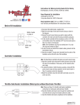
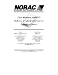
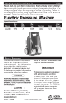
METRIC HEAT DEMON
INSTALLATION INSTRUCTIONS
This Metric Kit is designed to fit most models of motorcycles which do not have inserts inside the handlebar. Threaded
inserts like those on the inside of Yamaha handlebars need the weld drilled out or ground away so they can be removed.
Handlebars can also be replaced with aftermarket versions.
!!Warning!! A Service Manual is required to install this kit. The rider’s safety depends upon the correct
installation of this kit. If the procedure is not within your capabilities or you do not have the correct tools, have
your dealer perform the installation. Improper installation of this kit could result in death or serious injury.
WARRANTY AND DAMAGE: This product has a 1 (one) year Limited Warranty. The warranty does not cover misuse of
this product or operation outside of the design specifications. Symtec, Inc. WILL NOT be responsible for damages made to
products that are not installed properly. Symtec, Inc. products have recommended installation instructions that are written
to provide proper guidelines for product installations. Warranties WILL NOT be honored on broken items or damaged
electronics due to shorting or pinched wires.
Components: The ‘HEAT DEMON’ Metric Grip Warmers Kit includes the internal heaters for the handlebar, the 4
level temperature Controller, the backside clamp*, spacers**, cap screws and washers, the electrical wires and
connectors, rubber grommet, adhesive and a plastic snake and Template (Template is strictly a guide for punching holes
for the wire exiting out of the switch into the handlebar) to assist the installation.
* The Backside Clamp: This clamp is used to attach the controller to the handlebar if it is not possible to fasten the
controller to the brake reservoir, clutch reservoir or clutch bracket. Add the washers to the cap screws to attach the
controller to the backside clamp but do not over tighten.
**Spacers: These spacers are used to mount the controller on a 7/8 inch diameter handlebar. One spacer should be
inserted in the bottom of the controller and the other in the backside clamp.
Tools: A 3/8” Drill Motor, 5 sharp drills from 3/32” to 5/16” or a step drill, a hammer and center punch, a round file, a
pliers and wire cutter, a small straight blade screw driver, Allen wrenches, safety glasses and a felt tip marker.
Installation:
A. Open or remove the seat according to the service-manual instructions.
!!! Warning
!!! Warning
To protect against shock and accidental start-up of the vehicle, disconnect the battery cables, negative cable
first, before proceeding. Inadequate safety precautions could result in death or serious injury.
!!! Warning
!!! Warning
Always disconnect the negative battery cable first. If the positive battery cable should contact ground with
the negative cable installed, the resulting sparks may cause a battery explosion which could result in death
or serious injury.
B. Disconnect the battery, negative cable first, according to the service-manual instructions.
There are two options for installing the Heat Demon. Option A is doing the installation without removing the
handlebar and Option B includes the removal of the handlebar. Two holes need to be drilled in the handlebar and
the Option chosen depends on how comfortable the installer is on drilling holes in the bar. One advantage for
removing the handlebar is the Right Handlebar Control can be left intact during the installation. The disadvantage
is on some models the headlight and trim pieces need to also be removed along with the cables that are attached to
the handlebar.
Option A – Installation without removing the handlebar.
The 4 level Controller can be mounted on the left or right side of the handlebar so choose the side and
location that will provide the easiest installation and most convenient operation. The width between the
holes will allow the Controller to be mounted directly to the clutch bracket or brake reservoir on many
Yamaha, Honda, Kawasaki, Suzuki or Triumph motorcycles. On other motorcycles the back side clamp and
cap screws are provided to mount the Controller to the handlebar.
Metric_Heat_Demon_1 Rev 04/18/2011
1
This instruction will describe the installation of the Controller on the throttle or right side; however the same basic
steps would be followed for the installation on the clutch or left side, along with the heaters being switched.
1.
2.
3.
4.
5.
6.
7.
8.
9.
10.
11.
12.
13.
14.
15.
16.
17.
The power wires from the battery need to be brought out the right end of the handlebar to attach to the other
electrical wires. This will require drilling a hole in the handlebar, which will be described later, so mark a spot
with the felt tip marker behind the brake reservoir, on the bottom of the bar, or at the center of the bar where
wires would enter the handlebar.
The new 4 level Controller will replace the clamp that secures the brake reservoir to the handlebar, like shown
in the picture on the front of this package. A hole needs to be drilled in the side of the handlebar to install the
electrical wires from the bottom of the Controller. To assure that the Controller gets mounted in the same
location as the clamp, the location of the clamp should be marked before it is removed. With a felt tip pen
mark the handlebar where the brake reservoir is mounted. Also place a mark on the bar where the clamp and
reservoir meet so the Controller can be remounted in the same orientation around the handlebar.
With an Allen Wrench remove the clamp that holds the brake reservoir to the handlebar but hold the reservoir
against the bar where it was mounted. With the felt tip marker place a line on the handlebar that would be in
line with the center of the two screw holes in the reservoir.
Remove the reservoir and place the template that is included in the kit on the handlebar where the marks are
located. Place the centerline of the holes on the template over the line that you marked on the handlebar
indicating the center of the two screw holes in the brake reservoir. Rotate the template so the top edge of the
outline lines up with the mark where the clamp and reservoir meet. Place a mark on the handlebar for the hole
location.
Remove the switch housing and the Right Grip according to the service manual instructions and set aside or
leave hanging. Remember to insert a spacer between the rear brake light switch and the lever to keep the
switch from being broken.
Mark the location of the Left Grip and remove by twisting, heating, with air pressure, or injecting brake
cleaner fluid. Almost all grips can be removed without damage.
Center punch and drill a 5/16” hole in the side of the bar. At the spot marked earlier with the template, punch
a hole location with a center punch to pierce the chrome. Use safety glasses that completely cover the eyes
to protect from steel chips while drilling! Start with a small drill like a 3/32” size to make the initial hole.
Then use progressively larger drills or a step drill to increase the hole size to 5/16”. After the hole is drilled
use a round file or deburring tool to remove the sharp edges.
Another hole needs to be drilled in the handlebar to install the power cable. At the point marked in step 1,
center punch and drill a 5/16” hole and deburr.
With a small screwdriver, install the small rubber grommet into the second hole that was drilled in the
handlebar. The hole will not be round so the grommet needs to be worked into position. Be careful not to
push the grommet into the inside of the bar.
Install the Left Grip Heater. Clip (taper) off squared corners of the feed line on the opposite end of the drilled hole and
run it from the right end of the handlebar out the left end. Twisting the snake or inserting it vertically versus
flat can help to push around the corners.
Attach the white and yellow wires from the Left Grip Heater (Item 4) to the hole in the plastic snake and pull
them through the bar so they exit the right end. (See drawing below)
Push the left heater into the handlebar by squeezing it together and sliding it fully inside of the bar. The end of
the heater with the orange or black cap should be pushed in first. Cut the white and yellow wires to extend 4
inches beyond the right end of the handlebar.
Install the Left Grip. (Detailed installation instructions are on last page)
Push the 4 wires from the Controller through the hole in the side of the handlebar so they extend out the right
end of the bar. It works best to push them one at a time. Let the Controller hang down 1 inch from the bar.
The Red and Black non-stripped wires from the end of the 6 foot long power cable also need to be pushed
through the hole in the grommet at the back of the handlebar so they extend 4” out the right end of the
handlebar. Let the rest of the cable hang.
The wire connections are done near the right end of the handlebar. Hold the Right Grip Heater (Item 3) near
the end of the bar so these wires can be connected to the other wires that extend out the end of the bar. Use
the small connectors, from the parts bag, with 2 holes to connect the two green and then the two red wires.
Push the wires into the holes so they extend as far as possible into the connector. The wires can be viewed
from one side of the clear plastic. With the wires pushed to the end take pliers and push the yellow cap down
completely flat. This will pierce the wires and make the connection and some moisture resistant grease will
be pushed out of the connector. The cap needs to be pushed down completely so the grease comes out of the
connector otherwise it will not make the electrical connection. Wipe off the grease and pull on the wires to
make sure they are connected. If they are not connected there is one extra connector, or the wires will need to
be stripped and a small wire nut added or solder the wires.
Next use the connectors with 3 small holes to connect the 3 white, 3 yellow, and 3 black wires. Push the wires
into the connectors to the end and using pliers push the red cap down completely to pierce the wires and
Metric_Heat_Demon_1 Rev 04/18/2011
2
make the connection. Grease will also need to be pushed out to assure a good connection. Wipe off the
grease and pull on the wires to assure a good connection. The following wiring diagram shows the
connections.
18. Before doing the installation of the Heater, Controller, and Right Side components connect the Red and Black
wires of the power cable to 12V temporarily to confirm the proper operation. Press the button on the
Controller multiple times and confirm the 4 LED’s light from yellow to red and off. Also feel the left heater
to confirm it is starting to heat up. Do not leave on for more than 30 seconds to avoid overheating.
19. Fold the wires and connectors inside of the Right Grip Heater and push into the right end of the handlebar by
squeezing together and sliding it along with the wires until completely inside. The end of the heater with the
orange or black cap should be pushed in first and the power cable can be pulled out as the heater is pushed in.
20. Install the right switch housing, throttle control and grip according to the service manual. Attach the controller
to the brake reservoir and tighten to 60 in lbs with an equal gap between the two on each side.
21. Run the power cable along the wire harness conduit under the gas tank to the battery area. Add wire ties
where needed. The plastic snake can be used to bring the cable through the panels and under the gas tank
without removing it.
22. Connect the power wires to the Accessories circuit. Check the service manual or call your dealer for the
correct accessory wire connection. The Heat Demon kit draws 3 amps so a check should be made to assure
the circuit is not overloaded. Connect the Red wire to an accessory wire near the battery or behind the head
light with the red splice connector, from the parts bag. Connect the Black wire to a good ground location with
the ring terminal or to another black wire with the red splice connector.
23. Reconnect the battery cables. !!Warning!! Always connect the positive battery cable first.
24. Turn on the accessories switch and check that the Controller is wired properly by pressing the button and
confirm that each time it is pressed the 4 lights turn on and off.
Option B – Installation removing the handlebar.
1.
Complete steps 1 thru 4 above.
Metric_Heat_Demon_1 Rev 04/18/2011
3
2.
3.
4.
5.
6.
Loosen the screws on the Right Hand Control and Switch housing so the handlebar can slide out leaving the
assembly and Right Grip in position.
Remove the handlebar.
Follow steps 5 thru 13 above. An additional hole can be drilled in the bottom center of the handlebar if it is
desirable to run the power wires inside of the bar.
Reinstall the handlebar and tighten the screws on the Right Side Control.
Complete the installation following steps 14 to 24 above.
Operation:
The Controller will provide 4 levels of heat to the heaters inside of the handlebar. A thermistor senses the temperature
and provides a feedback to the Controller so a precise level of heat is supplied to the grips.
Press the button on the Controller once and the Yellow light or LED shows that the lowest level of heat is selected.
Press the button a second time and the Orange light or LED will indicate the next higher level of heat has been selected.
Pressing the button a third or fourth time will select higher levels of heat for colder conditions.
Pressing the button a fifth time will shut off all of the lights and the power.
Holding the button down for 3 seconds will lower the intensity of the LED’s for night operation. Holding it down again
for 3 seconds will adjust the LED’s for daytime use.
Left grip installation Instructions:
As the grips are heated the rubber or polymer material becomes more flexible and this makes the adhesion to the handlebar more
difficult. Likewise, new grips have a slippery mold release material on the inside of the grip and this also makes it more difficult to
adhere the grips. The following installation steps need to be followed to assure the grips will be secured to the handlebar.
The following instructions describe the application of a two part epoxy adhesive and the installation of the Left Grip. The various
rubber or polymer grip designs are typically the standard molded one piece or the metal and resilient material assembly like the ISO
version from Kuryakyn. The installation is different so each is described below.
A. Standard One Piece Grip
The one piece grip is typically smooth on the inside and will squeegee off the epoxy adhesive that is applied when it is pushed onto
the handlebar. Utilizing the wire that is included in the kit will keep the adhesive under the grip and secure it to the bar.
1.
2.
3.
4.
5.
Tape the wire to the top of the handlebar with electrical or transparent tape. The long straight end of the wire
should be even with the end of the handlebar and the tape applied next to the bent end.
If you have course sand paper roughen the inside of the grip. This will improve the adhesion of the grip to the
handlebar.
Cut the end of the epoxy adhesive pack and squeegee out both materials. Mix the two parts very well with the
enclosed craft stick. Place a small amount along both sides of the wire that is taped to the bar. Place about 1/3
of the remaining adhesive in the bottom inside of the grip and spread around with the wooden craft stick. Next
place half of the remaining epoxy adhesive in the center inside area and spread around the walls. Spread the
remainder of the epoxy adhesive around the inside entrance of the grip.
Slide the Left Grip over the wire and onto the handlebar holding the wire so it is not pushed off as the grip is
pushed on. Push the Left Grip onto the bar to the point that was previously marked for its location, and then
remove the tape and pull the wire out which will allow the epoxy adhesive to spread out inside of the grip. Wipe
off the excess epoxy adhesive from the end.
The epoxy adhesive will cure in 18 hours at room temperature or it will cure in 2 hours with the Heat Demon
Controller set to the highest heat level. Do not move the grips until the epoxy adhesive is cured.
B. Kuryakyn Style Grips
The following steps describe the installation procedure for this metal and polymer style grip that typically has many cavities on the
inside.
1. Complete step 2 from above. Sanding the inside of the grip improves the adhesion to the bar.
2. Follow step 3 above but skip the part about placing epoxy adhesive along the wire because it is not used for this
installation. When the entire adhesive is inside the Left Grip slide it onto the handlebar to the point previously
marked for its location. Rotate the grip to the desired orientation and wipe off any excess epoxy adhesive.
3. The epoxy adhesive will cure in 18 hours at room temperature or it will cure in 2 hours with the Heat Demon
Controller set to the highest heat level. Do not move the grips until the epoxy adhesive is cured.
124 Osborne Road
Fridley, MN 55432 (763) 571-9193
www.heatdemon.com www.symtec-inc.com
email: [email protected]
Metric_Heat_Demon_1 Rev 04/18/2011
4