1
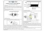
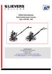
TECHNICAL MANUAL
INSTALLATION, USE AND MAINTENANCE INSTRUCTIONS
GV
GVO
STEAM BOILER
1
Dear Customer,
Thank you for choosing a boiler by IVAR.
In your interest and to maintain the highest level of performance and duration
of your appliance, we recommend that you follow the instructions contained in
this booklet and have regular maintenance performed by qualified personnel.
We would like to remind you that failure to follow the instructions contained in
this booklet may invalidate the guarantee.
2
CONTENTS
page
page
page
page
page
page
page
page
page
page
page
page
page
page
4 – GENERAL WARNINGS
5 – GENERAL SAFETY RULES
6 – “GV” BOILER TECHNICAL SHEET
7 – “GVO” BOILER TECHNICAL SHEET
8 – HANDLING AND POSITIONING
9 – PLANT TYPE
10 – STARTING UP OF THE BOILER
10 – STOP UP OF THE BOILER
10 – ONCE A WEEK
11 – FAULTS AND REMEDIES
12 – BOILER HOUSE
13 – BOILER CONNECTION
15 – ELECTRIC PANEL
16 – RECOMMENDED SPARE PARTS
3
GENERAL WARNINGS
This instruction booklet is an integral and essential part of the product.
Should the appliance be sold or transferred to another owner, or if you move
and leave the appliance behind, always ensure that this booklet accompanies
the appliance so that the new owner and/or installation technician can consult
it.
This appliance must be used for the purpose for which it was specifically
intended.
All contractual or non-contractual responsibility of the manufacturer is
excluded in the event of damages to persons, animals or things caused by
errors in installation, adjustment, maintenance and improper use.
The manufacturer's responsibility is excluded for all damage to persons and/or
things resulting from a clear risk for the user which he could have avoided by
taking suitable safety measures.
After having removed the packaging, check the contents for breakages. If you
are in doubt do not use the appliance, contact your supplier.
Do not leave the packaging materials (wooden cage, nails, staples, plastic
bags, polystyrene foam, etc.) within the reach of children, as they are potential
sources of risk.
The installation must be performed in compliance with the regulations in force,
following the manufacturer's instructions, by professionally qualified personnel.
The term “professionally qualified personnel” means persons with specific
technical skills in the sector of steam systems.
To guarantee the efficiency of the appliance and ensure correct operation, it is
indispensable to have regular maintenance performed by professionally
qualified personnel, following the manufacturer's instructions.
Any repairs to the appliance must be carried out using only original spare
parts.
If you decide not to use the appliance for a long period, ensure you have
professionally qualified personnel to carry out the necessary operations to
preserve the generator.
4
GENERAL SAFETY RULES
The use of any component utilising energy power, fuels and water requires
that certain fundamental rules be respected, such as:
Do not allow children or unskilled people to use the appliance;
If you notice smell of gas, do not turn on electric switches, household
appliances, telephone or any other objects that could cause sparks. If this is
the case:
- open doors and windows immediately to clear the air in the room;
- turn off the fuel taps;
- contact professional qualified personnel.
Do not touch the appliance with wet or damp parts of the body and/or with
bare feet.
Do not perform any maintenance and cleaning operations without having
disconnected the electric power and turned off the fuel supply tap(s).
Do not pull, disconnect, unwind electric cables coming from the boiler, even if
they are disconnected from the mains supply.
Do not block or reduce the ventilation openings in the room to prevent the
formation or toxic and explosive mixtures caused by gas leakage; it is also
uneconomic and polluting because it causes bad combustion.
Do not expose the appliance to atmospheric agents.
The generator has not been designed to work outdoors and is not provided
with automatic anti-freezing systems. Keep the boiler turned on in freezing
conditions.
Other important warnings to be respected:
-
If the power cable of the appliance is damaged, have it replaced by
professionally qualified personnel;
-
do not fix (and do not allow other persons to fix) electric cables on the
system pipes or near sources of heat;
-
ensure that the earthing cables of the appliance are not connected to the
water system;
-
do not touch the hot parts of the system (in particular the door and the
smoke box) as they normally remain hot even for some time after the
appliance has been turned off.
In the event of a water leak, turn off the system and contact exclusively
professionally qualified personnel.
5
GV
STEAM BOILER (12 bar)
type GV
Nominal capacity
Furnace capacity
Kw
Kcal/h
Kw
Kcal/h
125
200
300
400
550
700
87
139
209
278
383
488
75000
120000
180000
240000
330000
420000
98,9
158
237,5
316
435,3
554,6
85230
136400
204600
272750
375000
477300
Furnace pressure
mbar
2
2
3
3
3
3
Steam production
Kg/h
125
200
300
400
550
700
n°
1
1
1
1
1
1
stadi
1
1
2
2
2
2
dm3
38
38
54
54
68
77
A – mm
1250
1250
1350
1350
1350
1350
B – mm
800
800
900
900
900
900
C – mm
1500
1500
1500
1500
1500
1750
32
32
40
40
40
40
Ø - mm
115
115
160
160
160
160
Kg
600
600
800
800
900
960
Electric pump
Water content
Dimensions
Steam oulet connection
Stack connection
Empty weight
DN
I.VAR. INDUSTRY reserves the right to make any modifications considered necessary for improving production
6
GVO
STEAM BOILER (12 bar)
1 – WATER PUMP
2 – ELECTRIC ENGINE
3 – WATER FLOWMETER
4 – PANEL
5 – STEAM REGUL. PRESSURE SWITCH
6 – STEAM MAX PRESSURE SWITCH
7 – STEAM MANOMETER
TYPE
Nominal capacity
8 – STEAM SAFETY THERMOSTAT
9 – STEAM SAFETY PRESSURE SWITCH
10 – BURNER
11 – STEAM DELIVERY
12 – MANOMETER COCK
13 – SAFETY VALVE
14 – WATER PRESSURE SWITCH
15 – WATER MANOMETER
16 – START VALVE DISCHARGE
17 – STEAM TRAP
18 – FLAME SPY
19 – CONDENSATE DISCHARGE VALVE
20 – SMOKE SIDE CLEANING VALVE
21 – COUNTERWASH VALVE
GVO 200
kW
140
kcal/h 120000
450
314
270000
750
523
450000
1000
698
600000
1500
1045
900000
2000 2500 3000*
1395
1745
2093
1200000 1500000 1800000
kcal/h 133350
mbar
2
kg/h
200
n° - nr.
1
stadi - stages
1
dm³
45
A mm 1250
B mm 1000
C mm 1150
F mm
200
DN
32
Ø mm
120
kg
700
300000
3
450
1
2
89
1500
1150
1350
220
40
160
1400
500000
5
750
1
2
118
2000
1150
1350
220
40
200
1700
666700
5
1000
1
2
153
2400
1150
1350
220
50
250
2000
1000000 1333350 1666700 2000000
6
8
8,5
8,5
1500
2000
2500
3000
1
2
2
2
2
2
2
2
201
218
249
299
2650
3000
3300
3800
1350
1350
1350
1350
1600
1600
1650
1650
330
330
400
400
65
80
100
100
350
350
450
450
2500
3000
3200
3600
Furnace capacity
Furnace pressure
Steam production
Electric pump
Water content
Dimensions
Steam oulet connection
Stack connection
Empty weight
* 10 bar
I.VAR. INDUSTRY reserves the right to make any modifications considered necessary for improving production
7
HANDLING AND POSITIONING
For the lifting of the generators GVO, please see the diagram below.
GVO
200
450
750
1000
1500
2000
2500
3000
L min.
900
1100
1400
1700
1900
2200
2300
2750
8
PLANT TYPE
1 – GVO boiler
2 – water pump
3 – electric engine
4 – water pressure switch
5 – water manometer
6 – flame spy
7 – water flowmeter
8 – counterwash valve
9 – regulat.pressure switch
10 – max pressure switch
11 – safety pressure switch
12 – steam thermostat
13 – steam valve
14 – safety valve
15 – start valve discharge
16 – softener
17 – salt tank
18 – dosing pump
19 – water tank
20 – steam collector
21 – stop valves
22 – steam trap
23 – steam output
H – pump water level
25 – water to tank
26 – hard water
27 - filter
9
28 – discharges
29 – safety discharge
30 – condensate return
32 – burner
33 – no return valve
34 – air discharge
35 – tank discharge
36 – smoke side discharge
A) STARTING UP OF THE BOILER
A1)
A2)
A3)
A4)
A5)
Check the hardness of the water : max 0.5 °F.
Open drain valve 15.
Shut off the delivery valve 13.
Switch on the main switch on the electrical panel.
Switch on the pump switch on “MANUALE”.
Wait the water flows by the drain valve.
A6) Switch on the burner switch.
A7) Switch on the pump switch on “AUTOMATICO”.
Wait steam mixed with water flows by the drain valve.
A8) Close slowly the drain valve and contemporary open slowly the delivery
valve.
B) STOP OF THE BOILER
B1)
B2)
B3)
B4)
Switch off the burner switch.
Open the drain valve.
Close the delivery valve.
Switch the pump switch on “MANUALE”.
Wait the water flows by the drain valve.
B5) Switch off the main switch.
In this way the coil is full of water then in the best condition to avoid oxygen
corrosion.
C) ONCE A WEEK
Before of the operation described in B)
C1) Close the delivery valve. The boiler will stop for max steam pressure.
C2) Switch off the burner switch and pump switch.
C3) Open the counterwash valve 8 so that the coil will be cleaned in the
reverse direction.
10
FAULTS AND REMEDIES
FLOW SWITCH BLOCK
The burner goes out. The flow switch block lamp lights up on the control panel.
This means lack of water. Check the water level in the service tank.
STEAM BLOCK
The burner goes out and steam temperature thermometer pointer exceeds
200°C. The steam block lamp lights up on the control panel. This means a
capacity defect in the water pump or excessive fuel capacity in the burner
pump.
a - Water pump defect Check the pump capacity: open valve 13, collect the
outlet water in a bucket for 1 minute, then weigh it and determine the pump
capacity in liters/h. The capacity must coincide with the steam output of the
boiler.
E.G. : a 1.000 Kg/h boiler is equal to 16.7 litres/Minute. If the capacity is
insufficient:
1) remove the water pump bell, check the suction and delivery valves and
relevant seat. Change them if necessary.
2) open lid on the pump head and check the piston gaskets. Change them if
necessary (see water pump instructions).
b - Defect on fuel side Contact the burner service manual.
CHIMNEY BLOCK
The burner goes out. The chimney block lamp up on the control panel. To start
burner again, press the reconnection push-button on the thermostat. The
chimney block indicates that the boiler is dirty. Clean the boiler with a pressure
water jet and drain from plug.
Note The action of the safety equipment: flow switch, steam block, chimney
block, causes stoppage of the burner flame. The limit block lamp lights up on
control panel. To resume the operation, press “limit release’’ push button.
11
BOILER HOUSE
A boiler house is generally made up of the following equipment:
1 - The steam boiler itself, complete with burner.
2 - Water conditioning plant, generally composed of a water softener with
change of bases and possibly a mattering unit for conditioning products.
3 - Purified water and condensate collecting tank, having a capacity at least
one and half times the hourly steam output of the generator.
4 - Steam collector-header and distributor.
5 - Connection pipes between the single parts.
The “ boiler house “ dimension must be such as to guarantee an easy access to
the various part, means that the boiler operation can be checked and kept
under control; a bad access means negligence leading to probable breakdowns
due to carelessness.
The boiler room has to be ventilated and must therefore be provided with
suitable openings to allow proper aeration.
We remind you that the burner combustion air fan is up to 3.000 m3/h of air
for the larger models and for each generator, and this air must be able to enter
the boiler room without any difficulty.
12
BOILER CONNECTION
WATER CONNECTION
The hard water reaches the conditioning plant. This must be surrounded by
dividing wall; the floor should possibly be made in “gres”; independent drain
for backwashing the conditioner. When the softened water leaves the
conditioner it must then be forwarded to the purified water and condensate
collecting tank.
The condensate tank, especially if the water is at high temperature, must have
a minimum head of about 1.50 meters over the generator pump level.
RELATION BETWEEN THE WATER TEMPERATURE AT THE PUMP
AND HEAD, NECESSARY TO AVOID THE CAVITATION.
The connection piping between the tank and boiler must have an adequate
diameter.
Never make a rigid fitting between the boiler piping and pump - Interpose m.
0.30 of high temperature resisting flexible rubber hose.
Do not use elbows but bend pipes to avoid head loss.
A breather pipe should be applied to the condensate collecting tank and let
through to the outside of the room to discharge the fumes.
It is recommendable for the water pipings and tank to be galvanised.
13
FUEL CONNECTION
(see also burner instruction book)
These may be three types:
a - pipings for light oil (gas oil);
b - pipings for heavy oil (fuel oil);
c - pipings for gas.
Gas oil pipings
The pipings conveying oil from the tank to the pump and viceversa, must be
made with welded fittings for iron pipings and biconical fittings for copper
ones.
Fuel oil pipings
In this case it is always recommendable to prepare a plant having the day fuel
tank located in the boiler room and the transfer pump between this and the
storage tank. The day fuel tank must be complete with electric and steam
preheater (where possible and convenient), the piping from the day fuel tank
to the burner pump must be insulated and, in the event of heavy fuel oil,
wound with a heat tape.
Special instructions should be requested case by case.
Gas pipings
Connect the maingas network to the burner. For town gas it is advisable to
provide a pressure stabiliser.
CHIMNEY
The chimney is usually made of a sheet steel piping of suitable diameter which
must be taken from the boiler flange to the outside of the room over the top of
the roof. When its height exceeds 12 meter, a draught equaliser should be
provided at the base.
Should several boilers be connected to one chimney, it is important to make
sure that exhausts do not interfere with each other.
STEAM
The steam pipings must have an appropriate diameter PN 16 valves are always
used. The pipes must be insulated and the header must be provided with a
steam trap.
EXHAUSTS
Connect the exhausts to the traps, taking care to make suitable raisers to
avoid sprays.
ELECTRIC LINES
The electric lines are connected to the RST and N terminals of the boiler panel.
The cable section must be suitable to stand the installed electric power.
Check to ensure that the network voltage coincides with the one on the ratingplate and the wiring diagram.
14
WARNING
It is recommended to purge all the piping which have to be connected to the
boiler to ensure that they do not contain any foreign bodies such as fragments
of gaskets, welding slag or anything else which might damage the generator
equipment before finally connecting it to the boiler!
ELECTRIC PANEL
The control switches with relevant pilot lamps are installed on this panel.
1 - Main switch in position “1” supplies voltage to the panel.
2 - The green pilot lamp signals that the panel is live.
3 - The red lamps signal defects in working of various circuits.
4 - The main switch in position “0” cuts off the current to the panel.
5 - The main switch in position “1” starts up the boiler.
TROUBLES SIGNALLED BY THE PANEL LAMPS AND REMEDIES TO BE
TAKEN
1 - Feed water block lights out
The burner goes out - lights up on the panel - check whether there is water in
the service tank.
Pump defect: check the capacity in liters/minute - if capacity is insufficient
remove the pump bell - check gaskets and change them if necessary.
2 - Steam block lights out
The burner goes out, due to the lack of fuel delivery.
3 - Chimney block lights out
This indicates that the boiler is dirty on the fume side.
15
LIST RECOMMENDED SPARE PARTS
WATER PUMP
SAFETY
DEVICE
BOILER
BURNER
Suction valves
Delivery valves
Valves springs set
Valves seat gaskets set
Piston gaskets
Lid gaskets
Head gaskets
Manometer in glycerine bath
Thermometer with electric contacts
Contacts for thermometer
Steam pressure switch
Water pressure switch
Flow switch
Octal relay
Magnetic starter with over load and under
voltage protection
Type RT 124 thermostat
Pilot lamps set
Stop-running switch
Gaskets for door
Inspection window
Boiler inox diffuser
Electrode set (n.2)
Nozzles set (n.2)
Milled disk
Burner diffuser
Photoresistence
Gas oil pump
Hydraulic jack
Flame relay
16
NOTES
17
I.VAR INDUSTRY S.r.l.
Via S. Pierino, 4 (Z.A.I.) - 37060 Trevenzuolo – VERONA - Italy
Telefono 045/6680082 - Telefax 045/6680051 - P.IVA 02835480233
e-mail: [email protected] – Web site: www.ivarindustry.it
code: ist-GV-GVO-ing rev.00
18