1
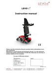
LEVO combi
SERVICE-MANUAL
This manual is for use by LEVO AG agents or their authorised dealers.
Read these instructions before servicing the wheelchair.
This service manual must be read in conjunction with the user manual.
Manufacturer:
LEVO AG
Anglikerstrasse 20
CH-5610 Wohlen
Schweiz / Switzerland
Tel:
Fax:
Internet:
Service and Distribution:
+41 (0)56 618 44 11
+41 (0)56 618 44 10
http://www.levo.ch
-1-
13.12.04
Table of Contents
1.
2.
3.
3.1.
3.2.
3.3.
3.4.
4.
5.
6.
7.
8.
8.1.
8.2.
8.3.
8.4.
8.5.
8.6.
8.7.
8.8.
8.9.
8.10.
8.11.
8.12.
8.13.
8.15.
8.16.
8.17.
8.18.
8.19.
8.20.
9.
10.
11.
11.1.
11.2.
11.3.
11.4.
Introduction ........................................................................................................................................................ 3
Health & safety ................................................................................................................................................... 3
Adjustments ........................................................................................................................................................ 3
Seat depth ............................................................................................................................................................. 3
Low shearing at the back ...................................................................................................................................... 3
Adjustment of the backrest ................................................................................................................................... 3
Electronic control system ..................................................................................................................................... 4
Repairs: general instructions............................................................................................................................. 4
Tools & torque settings ...................................................................................................................................... 4
Important points ................................................................................................................................................. 5
Recommended safety checks.............................................................................................................................. 5
Repairs................................................................................................................................................................. 7
Replacing the drive wheels ................................................................................................................................... 7
Replacing the tire of a drive wheel ....................................................................................................................... 7
Replacing the front wheels ................................................................................................................................... 8
Replacing the back wheel ..................................................................................................................................... 8
Replacing the wheel fork (at front and back)........................................................................................................ 9
Replacing the connector of the back low shearing system ................................................................................... 9
Replacing the motor disengaging cable (free wheel device) .............................................................................. 10
Replacing the driving motor ............................................................................................................................... 11
Replacing the batteries........................................................................................................................................ 11
Replacing the joystick module............................................................................................................................ 12
Replacing the power module .............................................................................................................................. 12
Replacing the ALM (Actuator-Lights-Module).................................................................................................. 13
Replacing the gas spring..................................................................................................................................... 14
Replacing the actuator "lift" ............................................................................................................................... 15
Replacing the actuator "lying" ............................................................................................................................ 15
Replacing the safety cut-out ............................................................................................................................... 16
Replacing bulbs .................................................................................................................................................. 16
Replacing the light (front, white)........................................................................................................................ 18
Replacing the indicator ....................................................................................................................................... 18
Testing the wheelchair...................................................................................................................................... 19
Cleaning............................................................................................................................................................. 19
Technical information ...................................................................................................................................... 20
Measurements (metric) ....................................................................................................................................... 20
Measurements (imperial) .................................................................................................................................... 21
General technical information ............................................................................................................................ 22
Electromagnetic Interference (EMI) ................................................................................................................... 23
-2-
13.12.04
1. Introduction
Apart from regular charging of the batteries and keeping the wheelchair clean the LEVO combi is
maintenance-free and no attention is required by the user.
Because of the complexity of the wheelchair the LEVO agent or authorised dealer should carry out
a safety check at least once per year.
This service manual is to be used by the LEVO agent or authorised dealer. The manual gives
information on how to perform a safety check and carry out repairs to the LEVO combi. This
manual provides a good service to the persons in charge of the maintenance of the LEVO combi.
And of course, the user appreciates the safety and the reliability of a well maintained wheelchair.
This manual must always be read and used with the user manual.
2. Health & safety
Accidents do occur. When working on or testing the wheelchair be aware of the dangers and take
care to ensure your own and other peoples health and safety.
3. Adjustments
The majority of the adjustments can be carried out by the user or his family and are covered in the
instruction manual. However, the LEVO agent should always, on delivery, adjust the wheelchair to
suit the user.
3.1.
Seat depth
The adjustment of the seat depth should only be done by the LEVO agent or authorised dealer. For
information consult the user instruction manual at section 7.1.
3.2.
Low shearing at the back
The adjustment of the low shearing at the back should only be done by the LEVO agent or
authorised dealer. For information consult the user instruction manual at section 7.5.
3.3.
Adjustment of the backrest
The adjustment of the backrest should only be done by the LEVO agent or authorised dealer. For
information consult the user instruction manual at section 7.6. and 7.7.
-3-
13.12.04
3.4.
Electronic control system
The preset settings are chosen to ensure safe operation. The settings are in compliance with all
relevant legal requirements regarding the entire operating range of the joystick and the speed
control. In case the preset settings don’t meet the needs of the user, the control system can be
programmed individually; the maximum speed might be decreased for example.
Warning: Programming should only be conducted by healthcare professionals with in-depth
knowledge of Penny&Giles electronic control systems. Incorrect programming could result in
an unsafe set-up of a wheelchair for the user. LEVO AG accepts no liability for losses of any
kind if the drive or stability characteristics of the wheelchair are altered without prior
notification and discussion with LEVO AG.
It is in the responsibility of the person programming the control system to make sure that the
stopping distance requirement specified for the country in which the wheelchair will be used is
satisfied. If the braking rate is low, the forward and reverse maximum speed settings may need to be
re-programmed. It is in the responsibility of the person programming the control system to make
sure that the settings are safe and to note any programming changes made.
4. Repairs: general instructions
Only a LEVO agent or their authorized dealers should carry out servicing and repairs to the LEVO
combi.
•
•
•
Repairs: For advice in all repairs in Switzerland contact LEVO AG, Switzerland. For all other
countries contact your local LEVO agent. Addresses are given at the front of this service
manual.
Major repairs: For all major repairs, e.g. bent or damaged frame, always replace complete
components. Never try to repair damaged steel work or components.
Replacement parts: Factory replacement components should be used in all repairs, these are
available from LEVO AG. To order parts see the parts list drawings and the correlative list,
both available at LEVO AG.
5. Tools & torque settings
The following tools are required to service the wheelchair:
•
•
•
•
•
•
Spanners and sockets: 8 mm through to 24 mm.
Hexagon key: 2 mm through to 8 mm.
Screwdrivers: 1 Nm through to 50 Nm.
Phillips head screwdriver and slotted screwdriver
Soft headed hammer
Snap through tool
-4-
13.12.04
Torque settings:
Bolt size
M4
M5
M6
M8
M10
Torque Nm
3
6
10
25
50
6. Important points
•
•
•
•
•
Do not reuse nuts. Always replace with a new nut.
Always use thread locking compound.
Always use recommended components and parts available from LEVO AG.
Do not modify or repair the frame.
LEVO AG is responsible for any repairs on gas springs, motors and electronic parts.
7. Recommended safety checks
The following safety checks should be carried out at least once per year. This should be done by
a LEVO agent or authorized dealer. If a fault is found do not allow the wheelchair to be used until
it has been corrected.
1.
Make sure that the backrest, options and additional material is fixed safely. Using a V-Trak
backrest system check the lever of the backrest. All levers have to be completely pushed
down. Repair any fault found immediately.
2.
Examine the wheelchair frame for any damage. Replace any damaged or faulty components.
3.
Examine the condition of the seat cushion and the backrest cover (standard version),
respectively the therapod back shell cover (V-Trak backrest system) and replace if necessary.
4.
Examine condition of all harnesses, straps and buckles and replace if necessary.
5.
Examine and operate the footrest mechanism. Replace any damaged or faulty components.
6.
Examine nuts, bolts, pivots and frame plugs for tightness and general condition. Replace any
faulty components.
7.
Examine the rear wheel, the front wheels and their castors for free rotation and security.
Optimize the rotation and repair any fault found.
8.
The tires are maintenance-free besides occasional cleaning. Use a damp cloth for cleaning.
Tires must get replaced when the tire's profile is worn down. (For more information please
consult sector 8.3. to 8.5.).
-5-
13.12.04
9.
Check the free wheel device and the motor disengaging lever for correct operation. Repair
any fault found.
10.
Check the mechanical function of the motor disengaging lever. Pull the motor disengaging
lever out and turn it simultaneously to the OFF position. At this stage it should be possible to
push the wheelchair. Pull the motor disengaging lever out and turn it simultaneously to the
ON position to activate the motor brakes. The power wheel should be blocked now. In case
the power wheels are not completely blocked, it is absolutely necessary to replace the motor.
11.
Check the powered function of the motor disengaging lever. Switch on the joystick module
and start driving forwards. Let of the joystick. As a reaction the wheelchair should stop and
the solenoid brakes of the motor should snap in evidence. Repeat this check driving
backwards and to each side. In case the motor brakes don't function correctly check the
battery indicator on the joystick module for any failure indication. Consult the controller self
help guide (user manual sector 23) for details about failure indications.
12.
Make sure all the connectors are properly inserted, that the brake solenoids are energized and
that the solenoid coil is not open or short-circuited by testing the two bigger pins on the motor
lead plug. If necessary, replace the motor.
13.
Check all electrical cables and wires for chafing and clamp spots. Replace if necessary.
14.
Check all electrical connectors for corrosion and security. Replace if necessary.
15.
Clean the batteries and terminals. Test the battery capacity and advise the customer of their
condition. Charge the batteries before returning the wheelchair to the customer.
16.
Check all MODE functions as standing-up and sitting as well as the optionally added
functions (lift, backrest reclining, seat tilt, lying to standing directly). Repair any fault found.
17.
Check all lights and indications. Replace components with failures.
18.
Use all functions and drive the wheelchair as a final check. In case you notice any kind of
problems arrange the fixing.
-6-
13.12.04
8. Repairs
8.1. Replacing the drive wheels
When removing a wheel, the wheelchair must be unoccupied. The wheelchair must be supported
(B) so that it neither falls over or moves when a wheel is removed.
• Pull off the protective end cap which covers the countersunk
screw.
A
• Remove the countersunk screw (A) using a 5 mm hexagon
key.
• Remove then the black washer (F, picture 2).
• Withdraw the wheel from the wheelchair.
• To mount the new wheel follow the instructions in the
B
1
reverse order.
8.2. Replacing the tire of a drive wheel
When replacing the tire, means removing a wheel, the wheelchair must be unoccupied. The
wheelchair must be supported so that it neither falls over or moves when a wheel is removed.
2
C
B1
A
B2
•
•
•
D
E
F
G
H
•
•
Remove the drive wheel as
described in sector 8.1.
Remove the four black
countersunk screws (G) to
take the flange (C) of the
wheel using a 5 mm hexagon
key.
Remove five screws (H) of
the rim using a 6mm hexagon
key.
Withdraw the rims (B1 and
B2) from the tire (A).
Reassemble in reverse order.
• To fit the rims to the tire use gunk to make it easier.
Important: Take note of the circulation direction indicated on the tire before fixing.
-7-
13.12.04
8.3. Replacing the front wheels
When removing a wheel, the wheelchair must be unoccupied. The wheelchair must be supported so
that it neither falls over or moves when a wheel is removed.
•
•
A
•
•
•
Pull off the protective end cap from the axle.
Loosen the hexagon screw and washer using a 13 mm
hexagon key and remove the screw, the washer and the nut
(A).
Withdraw the wheel from the fork.
Reassemble the new wheel in reverse order.
Make sure all washers are placed correctly!
3
8.4. Replacing the back wheel
When removing the wheel, the wheelchair must be unoccupied. The wheelchair must be supported
so that it neither falls over or moves when the wheel is removed.
•
•
•
•
4
Loosen the screw (A) using a 6 mm hexagon key and
remove the screw, the washer and the nut.
Withdraw the back wheel from the fork.
Reassemble the new wheel in reverse order.
Make sure all washers are placed correctly!
A
-8-
13.12.04
8.5. Replacing the wheel fork (at front and back)
When removing a wheel and/or a wheel fork, the wheelchair must be unoccupied. The wheelchair
must be supported so that it neither falls over or moves when a wheel is removed.
•
A
•
•
•
Loosen the hexagon spike (A) at the wheel fork axle as
much as it needs to withdraw the fork from the mount. (Use
a 24 mm hexagon key.)
Replace the wheel fork.
Reassemble the used wheel in case it is still in a good
condition. Doing so please follow the instruction in sector
8.3. respectively 8.4.
Mount the new wheel fork in the reversed order.
(Picture 3 shows all parts in details.)
5
8.6. Replacing the connector of the back low shearing system
As a standard a connector of medium size is fixed. The shearing range regarding the back
movement is 9 cm / 3,5". The replacement of this connecting piece using a shorter or a longer piece
causes a variation of 8 cm / 3" respectively 10 cm / 4" of the shearing range.
•
•
•
•
•
A
•
6
Raise the seat to its maximum upright standing position.
Switch off the joystick module.
Loosen the fillister head screw at the backrest tube as well as the
double-head screw at the seat plate using a 4 mm hexagon key.
Remove the mentioned screws, the washers and the connector.
First mount the upper end of the new connector at the backrest
tube. Make sure to put the two washers back in place.
After that mount the lower end of the new connector at the seat
plate using the corresponding punched hole (A on picture 6
and 7). Again make sure to put the two washers back in place.
A
7
-9-
13.12.04
8.7. Replacing the motor disengaging cable (free wheel device)
•
•
•
8
A
Raise the seat to its maximum upright standing position.
Switch off the joystick module.
Remove the cover of the motor loosening both screws using a
4 mm hexagon key.
B
Right hand side motor disengaging cable
• Cut the right hand side motor disengaging cable (B) from the
cable clamp (A). (See picture 8).
9
• Withdraw the motor disengaging cable backwards.
• Make sure the motor disengaging lever is at the ON position.
• Lead first the new motor disengaging cable through the
E
adjusting screw (C). The nut (D) should be centred at the
adjusting screw (C).
D
C
• Lead then the cable through the hole of the disengaging motor
and through the other hole in the metal piece (E) on the motor.
• Lead further the cable through the cable jacket and around the disengaging shaft.
• Adduct the cable that a slight tension occurs. The cable should not escapade of the disengaging
shaft spline.
• Tighten the pen headed slotted screw around the cable clamp using a slotted screw driver.
Left hand side motor disengaging cable
• Cut the left hand side motor disengaging cable (B) from the cable clamp (A). (See picture 8)
• Withdraw the motor disengaging cable backwards out.
• Make sure the motor disengaging lever is at the ON position.
• Lead first the new motor disengaging cable through the adjusting screw (C). The nut (D) should
be centred of the adjusting screw (C).
• Lead then the cable through the hole of the disengaging motor and through the other hole in the
metal piece (E) on the motor.
• Lead the cable through the small tubes at both side of the battery box.
• Lead further the cable through the cable jacket and around the disengaging shaft.
• Adduct the cable that a slight tension occurs. This cable should not escapade of the disengaging
shaft spline.
• Tighten the pen headed slotted screw around the cable clamp using a slotted screw driver.
First controlling: turn the motor disengaging lever to the OFF position and check if the motor is
unlocked. In case it is not unlocked turn the nut (D) on the adjusting screw (C) forwards as far as it
needs to unlock the disengaging motor, the lever set on the OFF position.
Second controlling: turn the motor disengaging lever to the ON position and check if the motor is
locked. In case it is still unlocked turn the nut (D) on the adjusting screw (C) backwards as far as it
needs to lock the disengaging motor, the lever set on the ON position.
•
•
Shorten the end of the cable at 15 mm and clamp the cable end-protector piece.
Fix the motor cover in the reverse order.
- 10 -
13.12.04
8.8. Replacing the driving motor
When removing the driving motor, the wheelchair must be unoccupied. The wheelchair must be
supported so that it neither falls over or moves while replacing the driving motor.
•
•
•
•
A
•
•
•
10
•
•
•
•
•
Switch off the safety cut-out.
Open the cover of the battery box and disconnect the
motor plug (A) from the power module.
Remove first the drive wheel as described in sector 8.1.
Remove the motor cover loosening the screws using a
4 mm hexagon key.
Loosen the motor disengaging lever cable.
Now loosen the four cylinder head screws (B) at the motor
using a 6 mm hexagon key.
Mount the new motor with the four cylinder head screws
(B) using the 6 mm hexagon key again.
Fix the disengaging motor cable as described in sector 8.7.
Reassemble the motor cover.
Mount the drive wheel in the reverse order.
Connect the motor plug to the power module.
Switch on the safety cut-out.
B
11
8.9.
Replacing the batteries
Caution: The battery box is heavy, take care when lifting and carrying.
Caution: When working on the batteries take great care not to short out the terminals with
any metal tools etc. Always remove wristwatches or jewelry. When reconnecting make sure all
wires are connected to the correct battery terminals.
Caution: Contact with acids is dangerous. If you come into contact with acids, rinse the
contaminated body parts immediately with water and consult your doctor. Take off
immediately using acid contaminated clothing.
Caution: Always wash your hands after working on the batteries.
- 11 -
13.12.04
• If possible, raise the seat to the fully upright position.
• Switch off the safety cut-out.
• Open the battery cover.
• Loosen the screws at the electrical contact of the
batteries using a 13 mm screw wrench and remove the
small metal terminal piece (A).
• Lift the batteries out of the battery box.
• Put the new batteries in the battery box.
• Reassemble in the reverse order.
A
B
12
The batteries should always be replaced as a complete set.
8.10. Replacing the joystick module
•
•
A
•
13
•
•
Switch off the joystick module.
Unplug the joystick cable at the back of the joystick
module.
Loosen the two hexagon screws (A) at the back of the
joystick module using a 3 mm hexagon key and remove
them.
Lift the joystick module.
Mount the new joystick module in the reverse order.
8.11. Replacing the power module
D
B
C
A
E
14
•
•
Raise the seat to its maximum upright standing position.
Switch off the safety cut-out on the battery box.
- 12 -
13.12.04
• Open the cover of the battery box.
• Unplug the following connections:
- ALM cable (A)
- left motor cable (B)
- battery cable (C), which is either red and black or red and blue
- right motor cable (D)
- joystick cable (E)
(all cables are listed from the left to the right hand side, see picture 14)
Please notice the interlocking of the different plugs:
• ALM and joystick plug: pull back the lock.
• Motor cable plug: press the release catch at both sides of the plug.
• Battery plug: press the release catch at the upper side of the plug.
•
The power module is fixed with a Velcro fastener at the bottom of the battery box.
•
Reverse the above to refit.
8.12. Replacing the ALM (Actuator-Lights-Module)
•
•
•
•
•
•
•
•
•
Raise the seat to its maximum upright standing position.
Switch off the safety cut-out.
Open the cover of the battery box.
Unplug the ALM cable of the power module pulling back the lock. (Consult sector 8.11. for
more information).
The ALM is fixed with a Velcro fastener at the bottom of the battery for keeping it in place
while driving.
Remove the ALM from the battery box.
Disconnect the plugs at the connector.
Connect the plugs of the new ALM along the scheme shown at the inside of the battery cover.
Reassemble the new ALM in the reverse order.
- 13 -
13.12.04
8.13. Replacing the gas spring
The gas spring serves for easy manual raising of the seat in case of any disorder considering of the
batteries or the actuator "standing" and you still need access to the battery box in order of any
repair.
The gas spring raises the seat and supports it in the standing position without the actuator "standing"
in use.
•
•
Raise the seat to the maximum standing position.
Lift the clip (B) on the upper part of joint of the gas spring
using a slotted screwdriver (A) and press the joint part off
the joint pivot (C).
Caution: Do not remove the clip!
Lift the clip on the lower part of the joint of the gas spring
using a slotted screwdriver and press the joint part off the
joint pivot.
Caution: Do not remove the clip!
Remove the gas spring now.
Mount the new gas spring in the reverse order pressing the
ends on the correlative joint pivot.
•
A
C
•
•
B
15
8.14. Replacing the actuator "standing"
17
16
A
•
•
•
•
•
•
•
•
B
A
Raise the seat to the upright standing position.
Switch off the joystick module and the safety cut-out.
Remove the quick-release axle (A, picture 16) from the upper end of the actuator.
Push the seat further to the upright position as high as it needs to remove the actuator off the
recess drilled into the seat support. In case the seat is already at the maximum standing position
the gas spring has to be unfixed at the upper end. (Read the instruction in sector 8.13.)
Remove the clip (A, picture 17) at the inside of the lower end of the actuator.
Press out the spike (B, picture 17), use a hammer and a snap through tool to strike the spike
carefully out of the rod.
Unplug the actuator from the battery box and remove it.
Reassemble the new actuator in the reverse order.
- 14 -
13.12.04
8.15. Replacing the actuator "lift"
•
•
•
•
•
•
If the chair is supplied with the relax/lying function as an option
get the chair in the maximum lying position. It is hard access to
the actuator "lift" if there is no such function added.
• Switch off the joystick module and the safety cut-out.
• Support the lower base of the yoke (A) using a log (B) or
wooden rod that might be a broomstick for example to secure
the lift from falling down. (See picture 18.)
• Unplug the actuator "lift" from the battery box.
18
• Remove the clip (A on picture 17) at the upper end of the
actuator.
Press out the spike (B on picture 17), use a hammer and a snap through tool to strike the spike
carefully out of the rod.
Remove the actuator from the upper end of the halter of the actuator.
Detach the clip (A on picture 17) at the lower part of the actuator and remove the spike as
described before.
Now remove the actuator.
Reassemble the new actuator "lift" in the reverse order.
Take care that the piston rod of the new actuator is retracted (inside). Start work at the lower
part of the actuator and connect the plug of the actuator at the battery box first. Retract the
piston rod until it fits to the halter of the actuator "lift".
A
B
8.16. Replacing the actuator "lying"
•
•
•
19
•
•
•
•
A
•
•
•
Raise the seat to the upright standing position.
Switch off the joystick module and the safety cut-out.
Disconnect the plug of the actuator "lying" from the
battery box.
Loosen the screw (A on picture 19) using a 8 mm flat
wrench.
Remove the back end of the actuator from the
connecting part.
Remove the clip (A on picture 17) at the front end of the
actuator.
Press out the spike (B on picture 17), respectively use a
hammer and a snap through tool to strike the spike
carefully out of the rod.
Press the front end of the actuator down and off the
halter. Pull it then to the front and off the back halter.
Now remove the actuator.
Reassemble the new actuator "lying" in the reverse order.
Take care that the piston rod of the new actuator is retracted (inside). Start work at the front part
of the actuator and connect the plug of the actuator at the battery box first. Retract the piston rod
until it fits to the halter at the back.
- 15 -
13.12.04
8.17. Replacing the safety cut-out
To replace the safety cut-out the seat needs to be in the standing position for access to the safety
cut-out and the battery box. In case the seat is locked in the sitting position or the safety cut-out is
set in the OFF position , then the actuator "standing" has to be detached at the upper end and the
seat has to be raised manually. (Consult sector 8.14 for instructions considering the detachment of
the actuator "lying".)
A
B
C
19
•
•
•
•
20
Remove the nut (A) at the safety cut-out switch using a 14 mm slotted screw driver.
Open the cover of the battery box.
Disconnect both connectors at the safety cut-out (B) loosening two thruss head screws (C) using
a small slotted screw driver.
Replace the safety cut-out in the reverse order.
8.18. Replacing bulbs
Important instructions for replacement of indicators, indicators and bulbs:
Caution: Always switch off the safety cut-out first before any part of the lighting
system will be replaced or fixed.
Caution: Never touch a bulb at the glass casing with bare fingers. This effects the life
time of the bulb most negatively.
The LEVO combi is supplied with the following types of bulbs:
- lights in front, white
12V / 3W, screw thread E10
- indicators in front/back, orange
24V / 10W, bayonet fixing
- lights at the backside, orange
24V / 5W, stick lock
- 16 -
13.12.04
Replacement of the bulb in a light (front, white)
•
21
•
•
B
Loosen the screw (A) using a small Phillips screwdriver
and remove the white cover plate (B).
Turn the bulb counter clock wise off the thread.
Replace the bulb in the reverse order.
A
Replacement of the bulb in a indicator (front/back, orange)
•
•
Loosen the screw using a small Phillips screwdriver and remove the orange cover plate.
Press the bulb smoothly into the thread and turn it simultaneously counter clock wise off the
thread.
Replace the bulb in the reverse order.
Replacement of the bulb in a light (back, red)
•
•
•
•
Open the cover of the battery box.
Turn the bayonet fixing (A) (the bulb is integrated in this part) counter clock wise and take it out
of the casing.
Remove the bulb from the thread.
Replace the bulb in the reverse order.
- 17 -
13.12.04
8.19. Replacing the light (front, white)
A
•
•
•
23
•
•
•
•
Disconnect the light plug (A) from the battery box.
Loosen the screws at the side using a 5 mm hexagon
key for removing the white light (B).
Loosen the Phillips head screw using the correlated
screwdriver and remove the cover plate from the light
(D).
Pull the bulb thread carefully out to unplug the
connectors.
Remove the hexagon screw (C) including the serrated
washer using a 5 mm hexagon key.
Demount the ligth.
Reassemble the new light in the reverse order.
D
C
B
8.20. Replacing the indicator
Blinker at the back
• Open the cover of the battery box.
• Demount the bulb thread of the blinker.
• Unplug all connectors and pull back the cables to the battery box.
• Remove the indicator.
• Reassemble the new indicator in the reverse order.
Blinker at the front
• Loosen the screw at the cover plate of the indicator using a Phillips screwdriver and remove the
cover plate.
• Loosen in the inside of the indicator casing the hexagon screw using the correlative 5 mm key.
• Remove the indicator from the base frame.
• Unplug all connectors.
• Reassemble the new indicator in the reverse order.
- 18 -
13.12.04
9.
Testing the wheelchair
Always perform full functional tests on the wheelchair when repairs have been completed and
before it is returned to the customer. Only return the wheelchair to the client when all faults
have been rectified.
10.
Cleaning
Before returning the wheelchair to the customer ensure the wheelchair is clean and well presented:
•
•
•
If there is any dirt it should be cleaned off using a damp cloth and then dried thoroughly.
For more stubborn stains wipe with a damp cloth using a mild solution of warm water and soap.
Never use furniture polishes or spirit to clean the frame.
- 19 -
13.12.04
11.
Technical information
11.1. Measurements (metric)
Model
S-M
L-XL
Seat width
Seat depth adjustable (incl. leg protector)
38 / 44 / 50 cm
36 - 47 cm
47 - 58 cm
Seat height (from top of cushion)
56 - 71 cm
Armrest height (from top of cushion)
11 - 27 cm
Footrest height (from top of cushion)
37 - 58 cm
Back height (incl. standard back upholstery)
43 cm
Overall width
66 cm
Overall length
110 cm
Smallest turning circle (diameter)
110 cm
Overall height (incl. standard back upholstery)
89 – 104 cm
Smallest turning radius
57,5 cm
Speed
0 – 10 km/h
Range (55 Ah batteries)
35 km
Max. gradient (standing position)
10°
Max. gradient (sitting position)
3°
Kerb climbing ability (standing position)
6 cm
Kerb climbing ability (sitting position)
4 cm
Measurements LxWxH (no back system included)
93 x 66 x 67 cm
Max. weight
170 kg
Max. total load
120 kg
- 20 -
13.12.04
11.2. Measurements (imperial)
Model
S-M
Seat width
Seat depth adjustable (incl. leg protector)
L-XL
15 /17/20"
14 – 18,5"
14,5 – 23 "
Seat height (from top of cushion)
22 – 28"
Armrest height (from top of cushion)
4 – 11"
Footrest height (from top of cushion)
14,5 – 23 "
Back height (incl. standard back upholstery)
17"
Overall width
26"
Overall length
43"
Smallest turning circle
43"
Overall height (incl. standard back upholstery)
35 – 41"
Smallest turning radius
22,6“
Speed
6mph
Range (55 Ah batteries)
22 miles
Max. gradient (standing position)
10°
Max. gradient (sitting position)
3°
Kerb climbing ability (standing position)
2,4“
Kerb climbing ability (sitting position)
1,6“
Measurements LxWxH (no back system included)
36x26x26,5"
Max. weight
375 pounds
Max. total load
265 pounds
- 21 -
13.12.04
11.3. General technical information
Drive wheels
Tires
Diameter 350 mm x 70 mm; 14” x 2¾“
No breakdown risk
Front wheels
Tires
Diameter 200 mm x 50 mm; 8” x 2”
No breakdown risk
Back wheels
Tires
Diameter 140 mm x 40 mm; 5½“ X 1½“
Speed
Drive motor actuator
Batteries 55 Ah
Range
Maximal tolerable gradient
Maximal kerb climbing
ability
Charger
Maximal load including
all objects carried along
Wheelchair category
No breakdown risk
0 - 10 km/h precision controlling
(There exist regulations considering speed limits for wheelchairs
in certain countries. These regulations have to be observed!)
24 V DC, 84 W
Maintenance-free lead accumulator in fleece technology
2 pcs. 12V / 55 Ah type "Sonnenschein" NPC 24-12 in series =
24V/24 Ah
Size: 260x132x240 mm/pc., weight: 18 kg/pc.
Max. discharge power for 6 minutes 72 A
Approximately 35 km / 22 miles
Note: Range is affected by the load carried, hills climbed and
temperature.
10°
6 cm/2,4”
Typ G2-300 24 V DC
The no-load voltage is 27.6 V, measured across pins 1 and 3 on
the charging plug.
120 kg/265 pounds
B
- 22 -
13.12.04
11.4. Electromagnetic Interference (EMI)
We recommend to consult the sector 12 of the user manual for important information about
electromagnetic interference.
Advice
Following the advice listed below should reduce the chance of unintentional brake release or
powered wheelchair movement.
Do not operate hand-held transceivers (transmitters-receivers), such as citizens band (CB) radios.
Do not switch on personal communication devices, such as cellular phones, while the powered
wheelchair is turned ON.
Be aware of any nearby radio or tv station transmitters and try to avoid going close to them.
If unintentional movement or brake release occurs, turn the powered wheelchair OFF as soon as it
is safe to do so. Report all incidents of unintentional movement or brake release to the
manufacturer, and note whether there was a radio wave source nearby.
Finally, be aware that adding accessories or components, or modifying the powered wheelchair,
may make it more susceptible to EMI. LEVO AG cannot take any responsibility for the effects of
EMI if your wheelchair has been altered in any way.
- 23 -
13.12.04