1
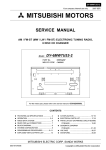
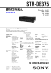
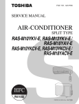
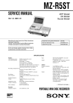
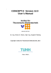
Service Manual
Model
DE-1
20-bit Dual Multi Effect Processors
CAUTION:
CAUTION
TO PREVENT ELECTRIC SHOCK, MATCH
RISK OF ELECTRIC SHOCK
DO NOT OPEN
WIDE BLADE OF PLUG TO WIDE SLOT,
FULLY INSERT.
ATTENTION:
CAUTION: TO REDUCE THE RISK OF ELECTRIC SHOCK,
POUR ÉVITER LES CHOCS ÉLECTRIQUES,
DO NOT REMOVE COVER (OR BACK).
INTRODUIRE LA LAME LA PLUS LARGE DE
NO USER-SERVICEABLE PARTS INSIDE.
LA FICHE DANS LA BORNE CORRESPONDANTE DE LA PRISE ET POUSSER
REFER SERVICING TO QUALIFIED SERVICE PERSONNEL.
JUSQU' AU FOND.
The lightening flash with arrowhead symbol,
within an equilateral triangle, is intended to
alert the user to the presence of uninsulated
“dangerous voltage” within the product's enclosure that may be of sufficient magnitude to
constitute a risk of electric shock to persons.
The exclamation point within an equilateral
triangle is intended to alert the user to the
presence of important operating and maintenance (servicing) instructions in the literature
accompanying the appliance.
“WARNING”
“TO REDUCE THE RISK OF FIRE OR ELECTRIC SHOCK,
DO NOT EXPOSE THIS APPLIANCE TO RAIN OR MOISTURE.”
SAFETY INSTRUCTIONS
1.
2.
3.
4.
5.
6.
Read instructions - All the safety and operating instructions should be read before the appliance is operated.
Retain instructions - The safety and operating instructions
should be retained for future reference.
Heed warnings - All warnings on the appliance and in the
operating instructions should be adhered to.
Follow instructions - All operating and use instructions
should be followed.
Water and Moisture - The appliance should not be used
near water - for example, near a bathtub, washbowl,
kitchen sink, laundry tub, in a wet basement, or near a
swimming pool, and the like.
Carts and Stands - The appliance should be used only
with a cart or stand that is recommended by the manufacturer.
9.
10.
11.
12.
13.
14.
15.
7.
8.
An appliance and cart combination should be moved with
care. Quick stops, excessive force, and uneven surfaces
may cause the appliance and cart combination to overturn.
Wall or Ceiling Mounting - The appliance should be
mounted to a wall or ceiling only as recommended by the
manufacturer.
Ventilation - The appliance should be situated so that its
location or position does not interfere with its proper ventilation. For example, the appliance should not be situated on a bed, sofa, rug, or similar surface that may block
the ventilation openings; or, placed in a built-in installation, such as a bookcase or cabinet that may impede the
flow of air through the ventilation openings.
16.
17.
Heat - The appliance should be situated away from heat
sources such as radiators, heat registers, stoves, or other
appliances (including amplifiers) that produce heat.
Power Sources - The appliance should be connected to a
power supply only of the type described in the operating
instructions or as marked on the appliance.
Grounding or Polarization - The precautions that should
be taken so that the grounding or polarization means of
an appliance is not defeated.
Power Cord Protection - Power supply cords should be
routed so that they are not likely to be walked on or
pinched by items placed upon or against them, paying
particular attention to cords at plugs, convenience receptacles, and the point where they exit from the appliance.
Cleaning - The appliance should be cleaned only as recommended by the manufacturer.
Nonuse Periods - The power cord of the appliance should
be unplugged from the outlet when left unused for a long
period of time.
Object and Liquid Entry - Care should be taken so that
objects do not fall and liquids are not spilled into the enclosure through openings.
Damage requiring Service - The appliance should be serviced by qualified service personnel when:
A. The power supply cord or the plug has been damaged;
or
B. Objects have fallen, or liquid has been spilled into the
appliance; or
C. The appliance has been exposed to rain; or
D. The appliance does not appear to operate normally or
exhibits a marked changed in performance; or
E. The appliance has been dropped, or the enclosure
damaged.
Servicing - The user should not attempt to service the appliance beyond that described in the operating instructions. All other servicing should be referred to qualified
service personnel.
DE-1
TABLE OF CONTENTS
1. SPECIFICATIONS . . . . . . . . . . . . . . . . . . . . . . . . . . . . . . . . . . . . . . . 4
2. CONTROLS, INDICATORS AND CONNECTORS . . . . . . . . . . . . 5
3. EXPLODED VIEW, PCB ASSEMBLY AND PARTS LIST . . . . . . 6
4. CIRCUIT & BLOCK DIAGRAMS . . . . . . . . . . . . . . . . . . . . . . . . 14
NOTES
* Parts List and circuit diagrams are given in this manual to assist the service technician in maintaining the Model DE-1.
* The following accessories are supplied with DE-1 as the standard accessories.
Owner's manual
: 8288441100 (for domestic & export model)
Foot assy, S
: 8260561000
* Following is the packing material for the Model DE-1.
Packing, L, DE-1
: 8228454000
Packing, R, DE-1
: 8228455000
Carton, inner, DE-1
: 8228729000
CAUTION
Parts marked with this sign are safety critical components. They must always be replaced with identical components.
Refer to the Fostex Parts List and ensure exact replacement.
3
DE-1
1. SPECIFICATIONS
INPUT & OUTPUT
INPUT (x 2)
Connector
Input level
Impedance
STEREO OUTPUT (L & R)
Connector
Output level
Impedance
FOOT SWITCH (x 1)
∅ 6 mm phone jack / unbalanced
-10 dBV
20 kΩ or more
∅ 6 mm phone jack / unbalanced
-10 dBV
10 kΩ or more
∅ 6 mm phone jack (Optional Model 8051)
OTHERS
Frequency Response
Dynamic Range
AD / DA Converter
Total Harmonic Distortion
Crosstalk
Sampling Frequency
+ 1, -2 dB at 20 Hz ~ 14.5 kHz
86 dB (IHF A)
20-bit
0.1 % at 100 Hz ~ 10 kHz (w / LPF)
60 dB at 1 kHz
32 kHz
GENERAL
Dimensions
Weight
Power Requirement
JPN
USA / CND
UK / EUR
Power supply
AC Adaptor
220 (W) × 187 (D) × 43 (H) mm
1.0 kg (excluding AC adaptor)
100 V AC
120 V AC
230 V AC
DC 9 V (center: positive), 600 mA
AD-9B
STANDARD ENVIRONMENT
Standard Temperature
Standard Humidity
20 ± 2 ºC
65 ± 5 %
ENVIRONMENT CONDITION
Characteristics Guaranteed
Temperature
Humidity
AC voltage deviation
Operation Guaranteed
Temperature
Humidity
AC voltage deviation
+ 5 ºC ~ + 40 ºC
30 ~ 70 %
± 5 % or less
+- 5 ºC ~ + 45 ºC
85 % or less
± 10 % or less
* Specifications and appearance are subject to change without notice for product improvement.
4
DE-1
2. CONTROLS, INDICATORS & CONNECTORS
< Front Panel >
EFFECT 1
TYPE
VARIATION
DLY+REV
VOCAL
PLATE
ADJUST
PARAM.1
MIX
DRY+EFF
6
DELAY
MISC
5
4
ROOM
CHO
3
9
S.HALL
L.HALL
PITCH 2
FLANGE 1
10
11
DLY+REV
MODE
SINGLE
DUAL
DRY
EFF
DRY+EFF
6
DELAY
MISC
5
4
ROOM
CHO
3
9
S.HALL
L.HALL
PITCH 2
FLANGE 1
10
11
VOCAL
PLATE
7
8
7
8
2
DRY
_
EFF
+
PEAK
PEAK
1
EFFECT 2
MIX
PARAM.3
ADJUST
PARAM.2
VARIATION
TYPE
3
4 5 6
7
8
POWER
9
10
11
12
< DUAL MODE >
1.
2.
3.
4.
5.
6.
EFFECT 1 TYPE SW
EFFECT 1 VARIATION SW
PEAK LED
EFFECT 1 ADJUST knob
EFFECT 1 MIX knob
MODE SW
7.
8.
9.
10.
11.
12.
EFFECT 2 TYPE SW
EFFECT 2 VARIATION SW
PEAK LED
EFFECT 2 ADJUST knob
EFFECT 2 MIX knob
POWER LED
7.
8.
9.
10.
11.
12.
Not functioning
Not functioning
PEAK LED (R channel)
PARAM. (PARAMETER) 2 knob
PARAM. (PARAMETER) 3 knob
POWER LED
< SINGLE MODE >
1.
2.
3.
4.
5.
6.
TYPE SW
VARIATION SW
PEAK LED (L channel)
PARAM. (PARAMETER) 1 knob
MIX knob
MODE SW
< Rear Panel >
EFF MUTE
R
L (MONO)
R
2
L (MONO)
DUAL MODE
SINGLE MODE
R
9V
1 (1&2)
L (MONO)
AD-9B
ONLY
MIN
DC IN
13
FOOT SW
14
OUTPUT 2
OUTPUT 1
15
16
MAX
MIN
MAX
INPUT
17
18
19
< DUAL MODE >
13.
14.
15.
16.
DC INLET socket
Foot SW socket
OUTPUT 2 jack sockets
OUTPUT 1 jack sockets
17. INPUT 2 jack socket
18. INPUT 1 (1 & 2) jack socket
19. INPUT LEVEL knobs
< SINGLE MODE >
13.
14.
15.
16.
DC INLET socket
Foot SW socket
Not functioning
Not functioning
17. INPUT L (MONO) jack socket
18. INPUT R jack socket
19. INPUT LEVEL knobs
5
DE-1
3. EXPLODED VIEW, PCB ASSEMBLY AND PARTS LIST
DE-1 OVERALL EXPLODED VIEW & PARTS LIST
Ref. No.
Part No.
Description
1
2
8221287000 Panel, front, DE-1
8221288000 Panel, top, DE-1
3
4
8221289000 Chassis, VC-8/DE-1
8274207000 PCB assy, Main, DE-1
5
6
8274208000 PCB assy, DSP, DE-1
8221292000 Bracket, volume, DE-1
7
8
8216700100 Shield, EMI, DE-1
8216702000 Sheet, screw, DE-1
9
10
8226189001 Knob, volume, grey, N
8226190001 Knob, volume, green, N
11
12
8226191001 Knob, volume, blue, N
8270818003 AC adaptor, AD-9B, USA/CSA
8270818006 AC adaptor, AD-9B, EUR
8270818007 AC adaptor, AD-9B, UK
13
6
8270818010 AC adaptor, AD-9B, JPN
8216636101 Cushion, button, FD-4/DE-1
DE-1
DE-1 OVERALL EXPLODED VIEW
BBT 3 x 6 BZn
BBT 3 x 6 BZn
BBT 3 x 6 BZn
12
2
BBT 3 x 6 BZn
BBT 3 x 6 BZn
7
4
6
6
5
10
13
11
9
13
8
3
BBT 3 x 6 BZn
8
1
BBT 3 x 8 BZn
7
C108
D102
R112
R111
C109
R113
R213
C6
BR54
C19
R211
D202
C14
R202
C20
C18
R212
C208
R210
C107
R22
R210
BC35
C105
R105
R106
R48
R204
R206
C102
C103
R47
BC34
BR55
C23
C106
D101
C207
R205
C203
C205
R103
R108
C204
C202
C2
BR52
R40
BC33
BR53
C24
BC32
R116
C112
C110
C22
R217
C114
R117
R118
1
30
C210
C1
R41
R13
R14
R15
R12
S
C214
R218
U203
3
PCB, MAIN, DE-1
8251526100
R115
C104
C111
R102
C113
C115
R114
R203
C206
R209
C213
U103
3
S1
C212
1
R216
D
BC31
R215
C201
BR50
C101
C21
C410
1
J5
1
R415
16
R416
R417
C414
R418
U403
3
J6
15
R45
1
D. S. P. BOARD
30
R318
C313
R317
C314
C310
R316
C312
U303
3
R315
J4
C211
BC30
R104
R107
D2
C311
BR51
J3
R314
J8
C412
C414
R201
D20
R44
R3
J7
R414
C15
R26
A1
C10
L9
R24
R42
C17
J2
3
R20
R101
C8
R2
R23
D4
• Parts side of
MAIN PCB
X1
R109
C7
R4
R18
C315
R16
R17
R208
R5
C314
C415
R11
R9
R207
R6
D1
R1
R10
C215
R114
W4
W3
W2
W1
C13
R8
R7
R21
U7
C16
1
R19
8
R25
DE-1 PCB PATTERN DRAWING
R43
1
3
C4
U2
L10
C12
L4
C5
C11 L11
C9
C3
J1
D3
DE-1
D3
L11
U2
C12
C5
C11
L1
R25
1
U7
C16
U19
R43
C9
3
1
R20
U3
3
U4
R23
R42
1
1
R3
D201
C10
R24
L9
C15
R26
C17
D4
C412
R416
C411
R415
1
16
R2
R418
R44
3
C413
1
U403
C21
A1
1
1
U303
R417
U202
C414
3
R45
R317 R316
R318
L5
R314
L6
C410
C312
15
30
R315
L2
C314
C310
C3
R216
1
U203
3
S1
C22
R217
U102
1
1
U103
3
R117
R118
L3
R12
R13
R14
R15
R41
C212
C1
PCB, MAIN, DE-1
single mode
dual mode
L4
R218
C214
L10
BR50
J3
C113
J4
R116
C111
J5
C311
BR51
J8
C24
R40
C2
BR52
BC33
BR53
BC32
L8
C203
C202
J6
BC30
C204
R202
C201
R201
R204
J1
D101
U1
R203
1
C414
C13
RC
R7
R8
R10
C213
C210
C212
C211
R215
BC51
U6
C6
U5
1
1
C1
C208
R210
C19
D202
R211
R46
C23
R212
BR54
C18
C20
L7
C104
J7
R103
R22
R213
R113
R111
R112
R47
C108
D102
C109
BC35
BC34
BR55
R110
1
R102
C101
R101
C203
U101
R108
J1
R214
C214
C102
2 3
C415
R9
R11
C313
C315
R17
R16
C114
R114
R205
C205
R208
R5
R206
R207
C207
R6
C206
R209
D1
R115
C115
W1
W2
W3
W4
C8
X1
R18
R106
R107
C107
D2
C106
R109
C7
R4
R104
R105
C105
• Foil side of MAIN PCB
DE-1
9
R21
DE-1
• Parts sides of DSP PCB
D. S. P.
module
PCB, DSP, DE-1
8251983001
C1
17
U2
60
R1
70
R2
C20
1
50
30
C18
20
C9
C21
100
1
J1
40
U1
90
C19
C22 C23
J2
80
X1
C17
1
1
C4
C3
C2
10
DE-1
• Foil sides of DSP PCB
30
(15)
C1
15
PCB, DSP, DE-1
8251983001
C5
C24
C6
C8
C13
C14
C15
C12
C11
C10
C7
C4
16
(1)
C3
C2
1
1
C16
11
DE-1
DE-1 Parts List
• MAIN PCB assy
Ref. No.
B101
Part No.
8274 2070 00
Description
PCB assy, Main, DE-1
8251 5261 00
Plain PCB, Main, DE-1
ICs
Ref. No.
Part No.
Description
U001
U002
8236 0852 00
8236 0320 01
QFP, DG, CPU, TMP87PM40AF
220, AN, regulator, NJM78M05FA
U003
U004
8236 5025 00
8236 5413 00
ST, AN, reset, NJM2103M
ST, AN, DC-DC, NJM2360M
U005, 006 8236 5050 11
U007
8236 0782 01
ST, AN, op amp, NJM2115M
PT, DG, driver, DTA114ES
U101
8236 5412 00
U102, 202 8236 5050 11
ST, AN, op amp, NJM4565M
ST, AN, op amp, NJM2115M
U103~403 8236 5043 00
PT, DG, driver, DTA314STP
DIODEs
Ref. No.
Part No.
Description
D001, 002 8234 5007 00
D003
8234 1046 02
HT, 1SS136
Opt., VT, LED, GRN, SR-332MC-TE7
D004
8234 0196 02
D101, 201 8234 1046 01
HT, DSK10C-BT
Opt., VT, LED, RED, SR-332MC-TE7
D102, 202 8234 5007 00
HT, 1SS136
RESISTORs
Ref. No.
12
Part No.
Description
R001~003 8230 1381 02
R004
8230 1381 03
HT, carbon, 1/4W, 1kΩ, 5%
HT, carbon, 1/4W, 10kΩ, 5%
R005, 006 8230 1381 01
R007~016 8230 1381 03
HT, carbon, 1/4W, 100Ω, 5%
HT, carbon, 1/4W, 10kΩ, 5%
R017
R018
8230 1383 31
8230 1381 03
HT, carbon, 1/4W, 330Ω, 5%
HT, carbon, 1/4W, 10kΩ, 5%
R019
R020
8230 1381 09
8230 1381 02
HT, carbon, 1/4W, 1Ω, 5%
HT, carbon, 1/4W, 1kΩ, 5%
R021
R022
8230 1388 22
8230 1383 01
HT, carbon, 1/4W, 8.2kΩ, 5%
HT, carbon, 1/4W, 300Ω, 5%
R023
R024
8230 1381 04
8230 1381 03
HT, carbon, 1/4W, 100kΩ, 5%
HT, carbon, 1/4W, 10kΩ, 5%
R025
R026
8230 1384 73
8230 1383 30
HT, carbon, 1/4W, 47kΩ, 5%
HT, carbon, 1/4W, 33Ω, 5%
R040~043 8240 2870 06
R044~047 8240 2920 01
Pot., PL, RT09, 10kΩB, XV092, 20
Pot., PL, RK16311, 10kΩB, ROT
R101, 201 8240 2870 07
R102, 202 8230 1382 03
Pot., PL, RT09, 50kΩA, XV092, 20
HT, carbon, 1/4W, 20kΩ, 5%
R103, 203 8230 1382 03
R104, 204 8230 1382 03
HT, carbon, 1/4W, 20kΩ, 5%
HT, carbon, 1/4W, 10kΩ, 5%
R105, 205 8230 1388 23
R106, 206 8230 1382 03
HT, carbon, 1/4W, 82kΩ, 5%
HT, carbon, 1/4W, 10kΩ, 5%
R107, 207 8230 1382 03
R108, 208 8230 1383 31
HT, carbon, 1/4W, 10kΩ, 5%
HT, carbon, 1/4W, 330Ω, 5%
R109, 209 8230 1383 31
HT, carbon, 1/4W, 330Ω, 5%
Ref. No.
Part No.
Description
R110, 210 8230 1381 53
R111, 211 8230 1381 82
HT, carbon, 1/4W, 15kΩ, 5%
HT, carbon, 1/4W, 1.8kΩ, 5%
R112, 212 8230 1385 63
R113, 213 8230 1383 01
HT, carbon, 1/4W, 56kΩ, 5%
HT, carbon, 1/4W, 300Ω, 5%
R114~414 8230 1381 04
R115~415 8230 1382 73
HT, carbon, 1/4W, 100kΩ, 5%
HT, carbon, 1/4W, 27kΩ, 5%
R116~416 8230 1381 04
R117~417 8230 1382 02
HT, carbon, 1/4W, 100kΩ, 5%
HT, carbon, 1/4W, 2kΩ, 5%
R118~418 8230 1381 04
HT, carbon, 1/4W, 100kΩ, 5%
CAPACITORs
ALU = Electrolytic type
CER = Ceramic type
PES = Mylar type
Ref. No.
Part No.
C001, 002 8232 8181 04
Description
VT, CER, 25V, 0.1µF, +80-20%, YF
C003
8232 1434 77
C004~006 8232 1421 07
VT, ALU, 16V, 470µF, 20%, SME-VB
VT, ALU, 10V, 100µF, 20%, SME-VB
C007, 008 8232 8013 30
C009
8232 8031 03
VT, CER, 50V, 33pF, 5%, SL
VT, CER, 50V, 0.01µF, +80-20%, YF
C010
8232 1461 05
C011~013 8232 8031 03
VT, ALU, 50V, 1µF, 20%, SME-VB
VT, CER, 50V, 0.01µF, +80-20%, YF
C014
C015
8232 8014 71
8232 8011 22
VT, CER, 50V, 470pF, 5%, SL
VT, CER, 50V, 0.0012µF
C016
C017
8232 1421 07
8232 1431 07
VT, ALU, 10V, 100µF, 20%, SME-VB
VT, ALU, 16V, 100µF, 20%, SME-VB
C018~022 8232 8031 03
C023, 024
VT, CER, 50V, 0.01µF, +80-20%, YF
N/A
C101, 201 8232 1431 06
C102, 202 8232 8011 00
VT, ALU, 16V, 10µF, 20%, SME-VB
VT, CER, 50V, 10pF ± 0.5pF, SL
C103, 203 8232 1421 07
C104, 204
VT, ALU, 10V, 100µF, 20%, SME-VB
N/A
C105, 205 8232 8011 00
C106, 206
VT, CER, 50V, 10pF ± 0.5pF, SL
N/A
C107, 207 8232 1431 06
C108, 208 8232 8181 04
VT, ALU, 16V, 10µF, 20%, SME-VB
VT, CER, 25V, 0.1µF, +80-20%, YF
C109
232 8031 03
C110~410 8232 1431 06
VT, CER, 50V, 0.01µF, +80-20%, YF
VT, ALU, 16V, 10µF, 20%, SME-VB
C111~411 8232 8011 00
C112~412 8232 1421 07
VT, CER, 50V, 10pF ± 0.5pF, SL
VT, ALU, 10V, 100µF, 20%, SME-VB
C113~413
C114~414 8232 1431 06
N/A
VT, ALU, 16V, 10µF, 20%, SME-VB
C115~415
N/A
Ref. No.
MISCELLANEOUS
Part No.
Description
E001
E002
J001
Jumper, F5
Jumper, F10
8245 5440 00
Connector, PL, jack, DC-Inlet,
YKB31-0014
DE-1
Ref. No.
J002~008
Part No.
8245 3390 04
Description
Connector, PL, jack, phone,
L001
8242 1962 23
YKB21-5074
Coil, pvt, 22µH, 5%, LF-5.0S
L002
8242 5011 21
Filter, ST, EMI, 120, 25%,
MMZ2012S
L003~006 8230 5000 00
L007, 008 8242 5011 21
Resistor, ST, carbon, 1/10W, 0Ω, 5%
Filter, ST, EMI, 120, 25%,
L009
8242 1976 83
MMZ2012S
Coil, pvt, 68µH, 5%, LF7.5
L010
L011
8242 1976 83
Jumper, F15
Coil, pvt, 68µH, 5%, LF7.5
S001
8253 6550 17
SW, PL, slider, 1-2, non-shortening,
SSSF1, cover
W001~004
X001
8256 1790 02
N/A
Resonator, PV, CER, 8MHz, EFOEN
Y801
Nut, phone jack
8245 3400 00
• DSP PCB assy
Ref. No.
B101
Part No.
Description
8274 2080 00
8251 9830 01
PCB assy, Main, DE-1
Plain PCB, DSP, DE-1
ICs
Ref. No.
U001
Part No.
8236 0849 00
Description
QFP, DG, DSP, AK7712AVT
U002
8236 0846 00
TSOP, DG, SRAM,
TC551001CFT-70L
RESISTORs
Ref. No.
R001
Part No.
8230 5001 01
Description
ST, carbon, 1/10W, 100Ω, 5%
R002
8230 5001 00
ST, carbon, 1/10W, 10Ω, 5%
CAPACITORs
ALU = Electrolytic type
CER = Ceramic type
PES = Mylar type
Ref. No.
Part No.
C001~004 8232 2181 06
Description
VT, ALU, 16V, 10µF, 20%, SRE
C005~015 8233 5041 03
C016
8233 5041 04
ST, CER, 25V, 0.01µF, 10%, CC20R
ST, CER, 25V, 0.1µF, 10%, CC20R
C017, 018 8233 5002 20
C019~021 8233 5041 04
ST, CER, 50V, 22pF, 5%, CC20SL
ST, CER, 25V, 0.1µF, 10%, CC20R
C022, 023 8233 5001 52
C024
8233 5041 03
ST, CER, 50V, 0.0015µF, 5%, CC20R
ST, CER, 25V, 0.01µF, 10%, CC20R
MISCELLANEOUS
Ref. No.
X001
J001, 002
Part No.
8256 1830 01
Description
Resonator, ST, CER, 16.384MHz,
8245 3260 15
EFOD
Connector, plug, 15P,
Abbreviation
QFP:
Quad Flat Package
220:
AN:
TO-220 type
Analog
DG:
ST:
Digital
Surface mounting Taping device
HT:
V:
Horizontal mount taping device
Vertical mount
VT:
PI:
Vertical mount Taping device
Penetrate mount I form (straight)
PL:
PT:
Penetrate mount L form (right angle)
Penetrate mount Taping device
PIT: Penetrate mount I form Taping device
TSOP: Thin Small Outline Package
IMSA-1068Z006
13
9V DC IN
2
3
1
/MUTE
AOUTL2
AOUTR2
AOUTL1
AOUTR1
AIN2+
AIN2-
AIN1+
AIN1-
R9
10K
/MUTE
6
7
V+
SI
C3
470/16
AGND
C16
100/10
AGND3
R11
10K
mode0
1
C9
0.01
3
3
GND CT
4
R14
10K
U2
78M05
GND
2
5
2
L9
68uH
C15
0.0012uF
INV
ES
SO
R16
10K
16
17
18
19
20
21
22
23
24
25
26
27
28
29
30
/PD_DSP
C4
100/10
A+5
R21
8.2K
R20
1K
D4
DSK10C
D-12
-12V
C11
0.01
L1
22uH
C12
0.01
ADGND
2
4
3
1
1
R25
47K
C10
1/50
6
5
D+9
D+5
D1
1SS136
AGND3
2
R46
8
R18
10K
AGND3
3
TYPE_B2
TYPE_B1
TYPE_A2
TYPE_A1
AD+5B
< <
AGND3 C8
33P
C7 33P
AGND3
P76
P77
P00
P01
P02
P03
P04
P05
P06
P07
P10//INT0
P11/INT1
P12/INT2/TC1
P13//DVO
P14//PPG
P15/TC2
P16
P17
P20//INT5//STOP
10KB
C14
470P
mode2 1
mode3 2
/PD_DSP<> 3
/PD_ADDA<> 4
/CS_DSP<> 5
/RST_DSP<> 6
/WRQ_DSP<> 7
8
/MUTE 9
10
WRDY_DSP >11
DRDY_DSP >12
13
14
15
16
17
18
19
2
R47
TYPE1
mode0
mode1
1
HI: MUTE OFF
LO: MUTE ON
10KB
3
/RST_CPU
JUMPER
JUMPER
JUMPER
JUMPER
1
D+5
D2
1SS136
RESET
Vsa Vsb V+
7
AGND3
R4
10K
S1
W4
W3
W2
W1
10KB
3
VARIATION1
Ct VSC OUTc GND
1
4
2
3
U3
NJM2103
R3
1K
AGND3
2
R45
TYPE2
AGND3
non
non
non
non
SLIDE SW
BEAD
L2
AD+5B
R26
33
D+9
/MUTE
C5
100/10
AD+5A
YKB21-5074
J2
10KB
3
MODE SW
2
R44
LO: single mode
Hi: dual mode
SCK
SO
WRDY_DSP
DRDY_DSP
SI
/CS_DSP
/WRQ_DSP
1
VARIATION2
ADGND
/PD_ADDA
/PD_DSP
/RST_DSP
D+5
AGND1
FOOT SW
1
2
3
4
5
6
7
8
9
10
11
12
13
14
15
To DSP
R10
10K
AGND1 AGND2 AGND3
1
A1
R8
10K
/RST_DSP
DSP MODULE
AGND3
R17
330
D+5 L11
68uH
Vout
AGND2
U4
NJM2360
Vin
R15
10K
A+5
AOUTL1
AOUTR1
AOUTL2
AOUTR2
CD CS
8
R12
10K
mode1
AIN1+
AIN1AIN2+
AIN2-
R13
10K
mode2
D+9
/WRQ_DSP
R19
1
AOUTL2
AOUTR2
AOUTL1
AOUTR1
/CS_DSP
D+9
ANALOG OUT
ANA_OUT.SCH
AIN2+
AIN2-
AIN1+
AIN1-
YKB31-0014
J1
/PD_ADDA
ANALOG IN
ANA_IN.SCH
R7
10K
mode3
D+5
SCK
CPU, MAIN, DE-1
P73
P72
P71
P70
< < < < < <
64
63
62
61
60
59
58
57
56
55
54
53
52
U1
TMP87CM40AF
AGND
BR51
non
BR50
non
A+5
AGND3
X1
8MHZ
< <
BC30
non
R22
300
<
D+5
C1
0.1
BC31
non
VBIAS4
51
50
49
48
47
46
45
44
43
42
41
40
39
38
37
36
35
34
33
> SO
<
> SCK
>
<
AGND
R2
1K
R1
1K
A+5
C13
0.01
100
VBIAS1
C6
100/10
D+5
R6
ADGND
BR53
non
BR52
non
A+5
R5
100
AGND
C2
0.1
AD+5A
< MIX1
< PARAM1
MIX2
PARAM2
ADGND
D3
POWER LED
P61/AIN1
P60/AIN0
VAREF
VASS
P54
P53
P52//PWM//PDO
P51/INT4/TC4
P50/INT3/TC3
P47/SO2
P46/SI2
P45//SCK2
P44/SO1
P43/SI1
P42//SCK1
P41
P40
P37
P36
P75
P74
P73
P72
P71
P70
VDD
P67/AIN7
P66/AIN6
P65/AIN5
P64/AIN4
P63/AIN3
P62/AIN2
TEST
P21/XTIN
P22/XTOUT
/RESET
XIN
XOUT
VSS
P30
P31
P32
P33
P34
P35
14
20
21
22
23
24
25
26
27
28
29
30
31
32
4. CIRCUIT & BLOCK DIAGRAMS
BC32
non
1
3
1
3
1
3
1
3
BC33
non
SO
SI
SCK
10KB
2
10KB
2
10KB
2
10KB
2
AGND
VBIAS2
BC35
non
VBIAS3
ADJUST1
MIX1
AD+5B
ADJUST2
MIX2
BR54
non
BC34
non
BR55
non
A+5
ADGND
R40
R41
R42
R43
AD+5A
DE-1
INPUT2
I
INPUT1
YKB21-5074
J7
YKB21-5074
J8
AGND
2
4
3
1
AGND
2
4
3
1
ANALOG IN, MAIN, DE-1
BEAD
L8
BEAD
L7
2
R201
50KA
AGND
1
3
50KA
2
R101
AGND
1
3
non
C24
non
C201
10u/16
AGND
AGND
C23
C101
10u/16
VBIAS1
R203
20K
R103
20K
VBIAS1
R202
20K
R102
20K
6
5
10p
U5B
NJM2115M
7
R204
10K
C202
C203
100/10
AGND
R205
82K
C204
NON
AGND
1
U5A
4 NJM2115M
8
AGND
C103
100/10
2
3
AGND
R105
82K
C104
NON
C18
A+5 0.01
R104
10K
C102
10P
5
1
AGND
R211
1.8K
2
3
6
5
1
0.01
C19
U101B
NJM4565
7
AGND
AGND
R209
330
AIN2+
PEAK
AIN1+
AIN2-
R208
330
LED
D201
R213
300
DIODE
D202
LED
PEAK
R113
300
DIODE
D102
AGND
AGND
0.1
AIN1-
C208
R108
330
D-12 0.01
4
8
0.1
C109
C108
A+5
R109
330
U101A
NJM4565
U6B
NJM2115M
7
R207 10K
10p
A+5
U6A
NJM2115M
R210
15K
4
8
A+5 C20
0.01
C205
6
R212
56K
10p
R111
1.8K
R107 10K
C105
AGND
3
2
R112
56K
C207
10/16
C206
NON
R206
10K
C106
NON
R106
10K
C107
10/16
R110
15K
A+5
DE-1
15
16
MUTE
DGND
R39
10K
2
3
U10
DTA114EK
1
D+5
D-12
R38
100K
ANALOG OUT, MAIN, DE-1
AOUTR1
AOUTL1
AOUTR2
AOUTL2
C210
10u/16
C110
10u/16
C410
10u/16
C310
10u/16
VBIAS1
R214
100K
VBIAS1
R114
100K
C112
100/10
C212
100/10
R216
100K
6
5
VBIAS1
R414
100K
VBIAS1
R314
100K
C312
100/10
C412
100/10
R416
100K
6
5
AGND
C413
NON
AGND
1
U202B
NJM2115M
7
R415
27K
C411
10P
C214
10u/16
C114
10u/16
4 U202A
NJM2115M
8
R316
100K AGND
2
3
10P
27K
C23
A+5 0.01
R315
C311
U102B
NJM2115M
7
R215
27K
C211
10P
AGND
C313
NON
AGND
C213
NON
AGND
1
U102A
4 NJM2115M
8
R116
100K AGND
2
3
AGND
C13
NON
27K
10P
C22
A+5 0.01
R115
C111
R217
1K
C414
10u/16
C314
10u/16
R117
1K
R417
1K
R317
1K
3
3
3
3
AGND
1
2
U403
DTC314TK
AGND
1
2
U303
DTC314TK
AGND
1
2
U203
DTC314TK
AGND
1
2
U103
DTC314TK
AGND
R218
100K
AGND
R118
100K
R318
100K
AGND
R418
100K
AGND
L4
0
0
L3
0
0
L6
0
L5
0
AGND
2
4
3
1
AGND
2
4
3
1
OUTPUT1L
(-10dBV)
OUTPUT2R
(-10dBV)
YKB21-5074
J6
(-10dBV)
OUTPUT2L
YKB21-5074
J4
OUTPUT1R
(-10dBV)
YKB21-5074
J3
YKB21-5074
J5
AGND
2
4
3
1
AGND
2
4
3
1
DE-1
1
2
3
4
5
6
7
8
9
10
11
12
13
14
15
HEDDER1-15
J1
AGND1
R1
100
D+5
SCK
SI
WRDY_DSP
DRDY_DSP
SO
/CS_DSP
/WRQ_DSP
/PD_ADDA
/PD_DSP
/RST_DSP
/PD_ADDA
/PD_DSP
/RST_DSP
C24
0.01
AGND2
C16
0.01
R2
C20
0.1
AGND1
C2
10u/16
D+5
C9
0.01
C8
0.01
C7
0.01
1
2
3
4
5
6
7
8
9
10
11
12
13
14
15
16
17
18
19
20
21
22
23
24
25
C4
10u/16
TSTI1
OPCL
/PDAD
/PDDA
/PD
/RST
TSTIO1
TSTIO2
TSTIO3
DVB
DVB
SDIN2
SDAD
SDOUT2
SDDA
SDDA2
SDOUT3
SDOUT1
SDIN1
SMODE
BCLK
LRCK
CLKO
DVDD
DVSS
C18
22P
AGND1 AGND1
C17
22P
X1
16.9344MHz
C6
0.01
C3
C15 C14 C13 C12 C11 C10
10u/16 0.01 0.01 0.01 0.01 0.01 0.01 AGND2
C21
0.1
C19
0.1
/CS_DSP
/WRQ_DSP
10
AD/DA
U1
AK7712A
SCK
SI
WRDY_DSP
DRDY_DSP
SO
A+5
C23
1500P
C22
1500P
100
99
98
97
96
95
94
93
92
91
90
89
88
87
86
85
84
83
82
81
80
79
78
77
76
DVB
DVB
DVDD
DVSS
DZFSET
DVDD
DVSS
IO7
IO6
IO5
IO4
IO3
IO2
IO1
IO0
/OE
A0
A1
A2
A3
A4
A5
A6
A7
A8
NC
AVB
VRADH
AVDD
AVSS
VRADL
VCOM
AINL+
AINLAINR+
AINRNC
VRDAH
AVDD
AVSS
VRDAL
AOUTL1
AOUTR1
NC
AOUTL2
AOUTR2
AVB
NC
DZF1
DZF2
XTI
XTO
TSTI2
/CS
/WRQ
DVSS
DVDD
SCLK
SI
WRDY
DRDY
SO
/CASRF
/RASCE
/WE
A16
A15
A14
A13
A12
A11
A10
A9
DVSS
DVDD
26
27
28
29
30
31
32
33
34
35
36
37
38
39
40
41
42
43
44
45
46
47
48
49
50
/WE
A16
A15
A14
A13
A12
A11
A10
A9
DSP, DE-1
75
74
73
72
71
70
69
68
67
66
65
64
63
62
61
60
59
58
57
56
55
54
53
52
51
AIN2-
AIN2+
AIN1-
AIN1+
C1
10u/16
AGND1
D+5
A0
A1
A2
A3
A4
A5
A6
A7
A8
D7
D6
D5
D4
D3
D2
D1
D0
8
20
19
18
17
16
15
14
13
3
2
31
1
12
4
11
7
10
C5
0.01 24
A0
A1
A2
A3
A4
A5
A6
A7
A8
A9
A10
A11
A12
A13
A14
A15
A16
CE2
/CE1
/OE
/WE
I/O0
I/O1
I/O2
I/O3
I/O4
I/O5
I/O6
I/O7
AGND2
1
2
3
4
5
6
7
8
9
10
11
12
13
14
15
TC551001CFT-70L
VSS
VCC
A0
A1
A2
A3
A4
A5
A6
A7
A8
A9
A10
A11
A12
A13
A14
A15
A16
U2
AOUTL1
AOUTR1
AOUTL2
AOUTR2
A+5
6
30
32
5
21
22
23
25
26
27
28
29
AGND1
D+5
D0
D1
D2
D3
D4
D5
D6
D7
HEDDER1-15
J2
DE-1
17
INPUT 2
INPUT 1 (1&2)
• DUAL MODE
INPUT
INPUT
A/D
A/D
VARIATION
VARIATION
ADJUST
EFFECT
PROCESSOR
TYPE
ADJUST
EFFECT
PROCESSOR
TYPE
DRY
EFF
EFF
DRY
DRY
EFF
EFF
DRY
18
MIX
MIX
BLOCK DIAGRAM
D/A
L (MONO)
D/A
R
OUTPUT 2
R
OUTPUT 1
L (MONO)
D/A
D/A
DE-1
INPUT R
INPUT L (MONO)
INPUT
INPUT
A/D
A/D
VARIATION
ADJUST ADJUST ADJUST
PARAM.1 PARAM.2 PARAM.3
EFFECT
PROCESSOR
TYPE
DRY
EFF
EFF
MUTE DATA
MUTE DATA
DRY
• SINGLE MODE
D/A
D/A
D/A
D/A
R
OUTPUT 2
L (MONO)
R
OUTPUT 1
L (MONO)
DE-1
19
MIX
FOSTEX CORPORATION 3-2-35 Musashino, Akishima, Tokyo, Japan 196-0021
FOSTEX CORPORATION OF AMERICA 15431 Blackburn Ave., Norwalk, CA 90650, U.S.A.
© PRINTED IN JAPAN MAR. 1999 8288780000