1
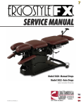
SERVICE MANUAL Domestic: Models 9510 and 9530 International: Models 9520 and 9540 Applies to Serial numbers 1000 and above ISO 13485 Certified TABLE OF CONTENTS FOREWORD . .. .. .. .. .. .. .. .. .. .. .. .. .. .. .. .. .. .. .. .. .. .. .. 1 1 SAFETY PRECAUTIONS .. .. .. .. .. .. .. .. .. .. .. .. .. .. .. 2 1.1 PRECAUTIONARY INSTRUCTIONS .. .. .. .. .. .. 2 2 NOMENCLATURE . .. .. .. .. .. .. .. .. .. .. .. .. .. .. .. .. .. .. 5 2.1 ERGOSTYLE HYLO TABLE EXTERNAL COMPONENTS.. .. .. .. .. .. .. .. .. .. .. 5 3 SPECIFICATIONS .. .. .. .. .. .. .. .. .. .. .. .. .. .. .. .. .. .. .. 6 3.1 PHYSICAL SPECIFICATIONS.. .. .. .. .. .. .. .. .. .. 6 4- TROUBLESHOOTING .. .. .. .. .. .. .. .. .. .. .. .. .. .. .. .. .. 7 4.1 ERGOSTYLE HYLO TABLE TROUBLESHOOTING .. .. .. .. .. .. .. .. .. .. .. .. .. .. 7 4.2 VISUAL INSPECTION .. .. .. .. .. .. .. .. .. .. .. .. .. .. 8 4.3 GROUND RESISTANCE TEST . .. .. .. .. .. .. .. .. .. 8 4.4 LEAKAGE TESTS .. .. .. .. .. .. .. .. .. .. .. .. .. .. .. .. .. 8 4.5 POWER ON/OFF TEST . .. .. .. .. .. .. .. .. .. .. .. .. .. 9 4.6 AUTO DROP TEST OPTIONAL .. .. .. .. .. .. .. .. 9 4.7 POWER SUPPLY TEST .. .. .. .. .. .. .. .. .. .. .. .. .. .. 9 4.8 STARTER RELAY TESTMODELS 9510 & 9530.. .. .. .. .. .. .. .. .. .. .. .. .. 10 5 REMOVAL & REPLACEMENT .. .. .. .. .. .. .. .. .. .. .. 12 5.1 POWER SUPPLY REMOVAL AND REPLACEMENT . .. .. .. .. .. .. 12 5.2 STARTER RELAY MODELS 9510 & 9530 REMOVAL AND REPLACEMENT . .. .. .. .. .. .. 14 5.3 STARTER CAPACITOR REMOVAL AND REPLACEMENT . .. .. .. .. .. .. 15 5.4 CONTROL BOARD REMOVAL AND REPLACEMENT . .. .. .. .. .. .. 16 5.5 HYDRAULIC ASSEMBLY REMOVAL AND REPLACEMENT . .. .. .. .. .. .. 17 5.6 HYDRAULIC SYSTEM .. .. .. .. .. .. .. .. .. .. .. .. .. 19 5.7 PELVIC MOTOR REMOVAL AND REPLACEMENT . .. .. .. .. .. .. 21 5.8 DROP ASSEMBLY REMOVAL AND REPLACEMENT . .. .. .. .. .. .. 22 6 MAINTENANCE.. .. .. .. .. .. .. .. .. .. .. .. .. .. .. .. .. .. .. 23 6.1 LUBRICATION POINTS .. .. .. .. .. .. .. .. .. .. .. .. 23 7 PARTS . .. .. .. .. .. .. .. .. .. .. .. .. .. .. .. .. .. .. .. .. .. .. .. .. 24 ErgoStyle™ HYLO Table 7.1 ELECTRICAL ENCLOSURE ASSEMBLY 115V . .. .. .. .. .. .. .. .. .. .. .. .. .. .. .. 24 7.2 ELECTRICAL ENCLOSURE ASSEMBLY 230V . .. .. .. .. .. .. .. .. .. .. .. .. .. .. .. 26 7.3 HYDRAULIC MOUNTING PLATE ASSEMBLY .. .. .. .. .. .. .. .. .. .. .. .. .. .. .. 28 7.4 FINAL ASSEMBLY .. .. .. .. .. .. .. .. .. .. .. .. .. .. .. 30 8 SCHEMATICS .. .. .. .. .. .. .. .. .. .. .. .. .. .. .. .. .. .. .. .. 38 9 WARRANTY .. .. .. .. .. .. .. .. .. .. .. .. .. .. .. .. .. .. .. .. .. 44 FOREWORD ErgoStyle™ HYLO Table Read, understand and follow all safety precautions and information contained in the manual. This information is intended to be used by trained and certified Chattanooga Group technicians. The specifications put forth in this manual were in effect at the time of the publication. However, owing to Chattanooga Group’s policy of continuous improvement, changes to these specifications may be made at any time without obligation on the part of Chattanooga Group. Chattanooga Group requires that all Field Technicians stay informed and trained on all changes pertaining to the ErgoStyle HYLO Table. As significant changes occur to the table, service bulletins will be made available on our website (chattgroup.com) in lieu of reprinted manuals. Technicians repairing the ErgoStyle HYLO Table agree to assume all risk and liability associated with this process. This table is to be used only under the prescription and supervision of a licensed practitioner. ©2006 Encore Medical Corporation or its affiliates, Austin, Texas, USA. Any use of editorial, pictorial, or layout composition of this publication without express written consent from the Chattanooga Group of Encore Medical, L.P. is strictly prohibited. This publication was written, illustrated, and prepared for print by the Chattanooga Group of Encore Medical, L.P. 1 1 SAFETY PRECAUTIONS ErgoStyle™ HYLO Table 1.1 PRECAUTIONARY INSTRUCTIONS The precautionary instructions found in this section and throughout this manual are indicated by specific symbols. Understand these symbols and their definitions before operating this equipment. The definition of these symbols are as follows: • Read, understand and practice the precautionary and operating instructions found in this manual. Know the limitations and hazards associated with your new treatment table. Observe any and all precautionary and operational decals placed on the table. • Do not operate this table in an environment where other devices are being used that intentionally radiate electromagnetic energy in an unshielded manner. Portable and mobile RF communications equipment can affect Medical Electrical Equipment. • This table generates, uses, and can radiate radio frequency energy and, if not installed and used in accordance with the instructions, may cause harmful interference to other devices in the vicinity. However, there is no guarantee that interference will not occur in a particular installation. Harmful interference to other devices can be determined by turning this table on and off. Try to correct the interference using one or more of the following: reorient or relocate the receiving device, increase the separation between the equipment, connect the table to an outlet on a different circuit from that which the other device(s) are connected and consult the Chattanooga Group Service Department for help. • Keep table out of high moisture environments. • This table should be operated, transported and stored in temperatures between 40° F (4.4° C) and 100° F (37.8° C), with relative humidity ranging from 30% - 80%. • Do not exceed table weight capacity of 400 lbs (182 kg). • Support the table section(s) with both hands when making any adjustments. • Inspect cables and connectors before each use. • Table should never be operated in an “out of level” position to the horizontal/ground plane greater than 5°. • Transport of this table should always be done with the “bed” section in the horizontal position and side axis tilt no greater than 10°. The table should be left in the horizontal position (down) when not in use. • The solid hydraulic tank plug should always be in place during table transport. Shipping the table with the breather plug may cause fluid leakage. • Use only Four Season Mineral Based AW 46 Hydraulic Oil. CAUTION – Text with a “CAUTION” indicator will explain possible safety infractions that could have the potential to cause minor to moderate injury or damage to equipment. WARNING – Text with a “WARNING” indicator will explain possible safety infractions that will potentially cause serious injury and equipment damage. DANGER – Text with a “DANGER” indicator will explain possible safety infractions that are imminently hazardous situations that would result in death or serious injury. DANGEROUS VOLTAGE – Text with a “Dangerous Voltage” indicator serves to inform the technician of possible hazards resulting in the electrical charge disbursement from certain components if handled or serviced improperly. NOTE – Throughout this manual, “NOTE” may be found. These Notes are helpful information to aid in the particular area or function being described. 2 1 SAFETY PRECAUTIONS ErgoStyle™ HYLO Table 1.2 PRECAUTIONARY INSTRUCTIONS (CONTINUED) • Do not use a damaged Mains Power Cord. Using a damaged Mains Power Cord may cause table damage, malfunction, electrical shock, fire, or personal injury. If the Mains Power Cord becomes damaged, discontinue use immediately and contact the dealer for replacement of the Mains Power Cord. • Disconnect the table from the power source before attempting any maintenance, installation, removal, or replacement procedures to prevent electrical shock and possible damage to the table. • This device should be kept out of the reach of children. • Do not allow any unsupervised patient access to the treatment table. • Do not sit or allow patients to sit on the Head Section, folding foot plate, or arm rests of the table. These sections were not designed to support sitting. • Do not lift table by Head Section, Arm Rest, or Foot Plate. • Do not smoke on or around table. • Unit contains hydraulic fluid, which may present hazardous conditions if leakage occurs. • In the event of visible hydraulic fluid leakage, do not attempt to use ascend or descend function of the table. • Use only accessories that are specially designed for the ErgoStyle HYLO treatment table. Do not use accessories manufactured by other companies on the ErgoStyle HYLO. Chattanooga Group is not responsible for any consequence resulting from using products manufactured by other companies. The use of other accessories or cables may result in increased emissions or decreased immunity of the ErgoStyle HYLO. • The ErgoStyle HYLO is not suitable for use in the presence of flammable anesthetics. • This table should only be operated under the prescription and supervision of a licensed medical practitioner that is familiar with the precautionary measures and operational functions associated with the table being used. • Do not remove the covers. This may cause table damage, malfunction, electrical shock, fire or personal injury. There are no user-serviceable parts inside the table. If a malfunction occurs, discontinue use immediately, disconnect the Mains Power Cord from the outlet and consult the dealer for repair service. • Do not use the table near devices such as Xray units or diathermy units. These units may emit high frequency noise that may affect the operation of the table. • Do not permit any foreign materials or liquids to enter the table. Take care to prevent any foreign materials including, but not limited to, inflammables, water, and metallic objects from entering the table. These may cause table damage, malfunction, electrical shock, fire, or personal injury. • The tool, lubrication and locking compound requirements listed are critical to maintenance and repair of the table. • Failure to use and maintain the table and its accessories in accordance with the instructions outlined in this manual will render the warranty void. • This device should only be used under the continued supervision of a licensed practitioner. • Make certain that the unit is electrically grounded by connecting only to a grounded electrical service receptacle conforming to the applicable national and local electrical codes. • Care must be taken when operating this equipment adjacent to or stacked with other equipment. Potential electromagnetic or other interference could occur to this or other equipment. Try to minimize this interference by not using other equipment in conjunction with it. • Never place your hands or feet near the working mechanism of the table when making any and all adjustments to height or table sections. • The table sections should be locked before the loading or unloading of a patient. Do not reposition or allow the patient to get on or off the table while the table is ascending or descending. • Do not leave the table unlocked and unattended at any time. 3 1 SAFETY PRECAUTIONS ErgoStyle™ HYLO Table 1.2 PRECAUTIONARY INSTRUCTIONS (CONTINUED) • Do not connect the table to an electrical supply without first verifying that the power supply is grounded and of the correct voltage. Use of an electrical supply that is not grounded and/or of the incorrect voltage may cause table damage, malfunction, electrical shock, fire, or personal injury. Your table was constructed to operate only on the electrical voltage specified on the Voltage Rating and Serial Number Plate. Contact the Chattanooga Group dealer if the table is not properly rated. • Do not allow anything to be under the table while the table is in operation. • Do not move or elevate any cushion section while the patient’s weight is on that section. • Do not reposition or allow the patient to get on or off table while any of the drops are in the cocked or engaged positions. • Do not allow anything to be under the table while the table is descending. • Do not reposition or allow the patient to get on or off the table while the table is ascending or descending. • This table should only be operated by trained personnel familiar with the precautionary measures and operational functions associated with the table being used. 4 2 NOMENCLATURE ErgoStyle™ HYLO Table 2.1 ERGOSTYLE HYLO TABLE EXTERNAL COMPONENTS The nomenclature graphics below, Figure 2.1, indicate Know the components and their functions before the general locations of the major components of the performing any operation of or service to the ErgoStyle HYLO Table. ErgoStyle HYLO Table. 2 1 19 18 3 17 16 15 14 4 13 12 10 11 5 9 6 8 7 FIGURE 2.1 1. 2. 3. 4. 5. 6. 7. 8. 9. 10. Head Cushion Adjustment Head Piece Cushions Thoracic/Lumbar Cushion Pelvic Cushion Adjustable Ankle Rest Cushion Foot Plate Adjustable Glide Leveler Table Tilt Foot Control Power Supply/Control Board Housing Hydraulic Subassembly 11. 12. 13. 14. 15. 16. 17. 18. 19. 5 Pelvic Elevation Release Lever Pelvic Drop Cocking Lever (Optional) Pelvic Drop Tension Control (Optional) Pelvic Section Gap Adjustment Breakaway/Elevating Chest Release Lever (Optional) Combined Section Adjustment for Patient Height Forward/Toggle Drop Tension Control Tilt Release Button Arm Rest Cushion 3 SPECIFICATIONS ErgoStyle™ HYLO Table 3.1 PHYSICAL SPECIFICATIONS CL 59 in (150 cm) 26 in (66 cm) 23.50 in (60 cm) 74 in (188 cm) CL FIGURE 3.1 Voltage Models 9510 and 9540. . . . . . . . . . . . . . . . . . . . . . . . . . . . . . . . . . . . . . . . . . . . . . . . . . . . . . . . . . . . . . . . . . . . . . . . . . . . . . . . . . 115 VAC Models 9520 and 9530. . . . . . . . . . . . . . . . . . . . . . . . . . . . . . . . . . . . . . . . . . . . . . . . . . . . . . . . . . . . . . . . . . . . . . . . . . . . . . . . . . 230 VAC Motor (all Models) . . . . . . . . . . . . . . . . . . . . . . . . . . . . . . . . . . . . . . . . . . . . . . . . . . . . . . . . . . . . . . . . . . . . . . . . . . . . . . . . . . . . . . . . 1/3 HP AC Frequency . . . . . . . . . . . . . . . . . . . . . . . . . . . . . . . . . . . . . . . . . . . . . . . . . . . . . . . . . . . . . . . . . . . . . . . . . . . . . . . . . . . . . . . . . . . . . . . . . . 50/60 Hz Current Models 9510 and 9540. . . . . . . . . . . . . . . . . . . . . . . . . . . . . . . . . . . . . . . . . . . . . . . . . . . . . . . . . . . . . . . . . . . . . . . . . . . . . . 5.8 A / 4.8 A Models 9520 and 9530. . . . . . . . . . . . . . . . . . . . . . . . . . . . . . . . . . . . . . . . . . . . . . . . . . . . . . . . . . . . . . . . . . . . . . . . . . . . . . 2.4 A / 1.9 A Fuses Models 9510 and 9540. . . . . . . . . . . . . . . . . . . . . . . . . . . . . . . . . . . . . . . . . . . . . . . . . . . . . . . . . . . . . . . . . . . . . . . . . . . . . . . . T10 L250V Models 9520 and 9530. . . . . . . . . . . . . . . . . . . . . . . . . . . . . . . . . . . . . . . . . . . . . . . . . . . . . . . . . . . . . . . . . . . . . . . . . . . . . . . . . . . . 3.15 A Lifting Capacity . . . . . . . . . . . . . . . . . . . . . . . . . . . . . . . . . . . . . . . . . . . . . . . . . . . . . . . . . . . . . . . . . . . . . . . . . . 400 lbs (182 kg) Maximum Electrical Classification . . . . . . . . . . . . . . . . . . . . . . . . . . . . . . . . . . . . . . . . . . . . . . . . . . . . . . . . . . . . . . . . . . . . . . . . . . . . . . . . . . . . . . . Class I Electrical Type. . . . . . . . . . . . . . . . . . . . . . . . . . . . . . . . . . . . . . . . . . . . . . . . . . . . . . . . . . . . . . . . . . . . . . . . . . . . . . . . . . . . . . . . . . . . . . . . .Type B Duty Cycle . . . . . . . . . . . . . . . . . . . . . . . . . . . . . . . . . . . . . . . . . . . . . . . . . . . . . . . Intermittent- Maximum 1 minute On, 9 Minutes Off Weight of Table* . . . . . . . . . . . . . . . . . . . . . . . . . . . . . . . . . . . . . . . . . . . . . . . . . . . . . . . . . . . . . . . . . . . . . . . . . . . . . . . . . . . . 405 lbs (184 kg) Meets Directives: 93 /42 /EEC IEC/UL/EN: 60601-1 EN 60601-1-2 * Basic Table (Without any Drops) 0413 6 4 TROUBLESHOOTING ErgoStyle™ HYLO Table 4.1 ERGOSTYLE HYLO TABLE TROUBLESHOOTING A. General- Electronic 1. Information within this section in respect to electronic components is intended to aid in troubleshooting the Printed Circuit Board (PCB)'s of the ErgoStyle HYLO Table to “Board Level” only. These tests are the standard testing procedures and methods used at the factory before shipment of the unit. 2. Chattanooga Group provides techniques to determine whether or not a PCB is bad. PCB are not designed for field repair and are replaced. Attempting to repair a PCB or using parts other then Chattanooga Group will void the warranty. 3. Once a particular PCB has been determined as bad, replace the PCB. Use only Chattanooga Group replacement parts and hardware. B. General- Replacement Components Critical component replacement parts for the table are available as subassemblies only. Individual components of these subassemblies will not be made available by Chattanooga Group. C. General- Tests and Repair Procedures 1. Certain tests and repair procedures may require the use of special tools and/or fixtures. These will be listed at the particular test where they are required. Testing with any other special tool or fixture other than those stated could give erroneous readings or test results. Always perform the tests exactly as stated to ensure accurate results. 2. Test equipment settings will be listed for each test performed prior to the respective test to ensure the test is performed to Chattanooga Group standards and ensure proper readings. D. Tools, Fixtures, and Equipment Required 1. Dielectric Withstand (Hi-Pot) and ground resistance tester. NOTE: Adjust Dielectric Withstand tester to indicate fault with 120 kOhm load across the output when at specified test voltage. 2. Required Hand Tool • #2 Phillips Screwdriver • Flat Blade Screwdriver • Allen Wrenches • SAE- Allen Wrenches- 3/32 in through 5/16 in • Metric- Allen Wrenches- 2.5 mm through 6 mm • SAE- End Wrenches- 3/8 in through 3/4 in 7 3. 4. 5. 6. 7. • SAE- Sockets- 5/16 in through 3/4 in • Ratchet to accommodate sockets • Insulated Needle Nose Pliers • Torque Wrench with a minimum capacity of 100 ft lbs (150 N-m) • Measuring Rod approximately 8 in (203 mm) long and marked at 2-5/8 in (66.675 mm) from one end Overhead Lifting Device with lifting strap Digital Multimeter Grounding Strap Mobile Four Seasons AW46 Hydraulic Oil (ISO VG 46) Air compressor with adjustable regulator • This hydraulic system was designed specifically for use with Mobile Four Seasons AW46 Hydraulic Oil (ISO VG 46) only. Use of any other oil may cause erratic operation of the table and will render the warranty void. • Maintain proper Hydraulic Oil level. Do not overfill the reservoir. Overfilling could cause oil to spill during operation of the table. • The tool, lubrication, and locking compound requirements listed are critical to component removal and replacement of the unit. • The hardware, bolts, nuts, and screws used to assemble the ErgoStyle HYLO are SAE and metric. Therefore, it will be necessary to obtain SAE and metric tools for removal and replacement of components. • The lubricant and locking compound listed are crucial in the assembly of certain components to ensure patient safety and efficient operation of the unit. 4 TROUBLESHOOTING ErgoStyle™ HYLO Table 4.2 VISUAL INSPECTION A. General Visually inspect the table. 4.3 GROUND RESISTANCE TEST A. Voltage Specifications Models 9510 and 9530 . . . . . . . . . . . . . Input: 115 VAC 50/60 Hz, 5.8 A / 4.8A Models 9520 and 9540 . . . . . . . . . . . Input: 230 VAC 50/60 Hz, 2.4 A / 1.9A B. Specification Maximum Acceptable Resistance: 100 milliohms C. Equipment Required Milliohm Meter D. Test Place the table on a level work surface. Place one meter probe on the ground prong of the Mains Power Cord and the other to any exposed metal or screw on the unit. See Figure 4.1. NOTE: U.S.A. power cord is illustrated in Figure 4.1. FIGURE 4.2 4.4 LEAKAGE TESTS • A table that is failing the dielectric withstand and/ or leakage tests could indicate serious internal system problems. Do not place the table back into service. Send the table to the factory for repair. Do not attempt to repair the table in the field. EXPOSED METAL GROUND PRONG Test Voltage Spec . . . . . . . . . . . . . . . . . . . . . . . . . . . . . .1500 V Conduct all necessary leakage tests as required per “Chapter 8 Electrical Equipment” of the 2005, or later, edition of the NFPA (National Fire Protection Association) “Health Care Facilities” standards. See Figure 4.3. FIGURE 4.1 The head extension frame is to be assembled with a detent screw (P/N 95725) and a nut (P/N 21024) that would allow constant contact with the grounded base of the table. See Figure 4.2. Check to verify that the parts are installed properly. If not, install the screw and nut on the head extension frame or tighten the screw and nut to seat. 8 4 TROUBLESHOOTING ErgoStyle™ HYLO Table FIGURE 4.4 D. Test Results 1. If the drops work, the table has passed the test. 2. If the drops don't work, the table has failed the test. Contact Chattanooga Group to obtain Factory Service. FIGURE 4.3 NOTE: The NFPA "Health Care Facilities" standards are specific to the U.S.A. All other technicians should verify their country's requirements for these tests. 4.7 POWER SUPPLY TEST A. Output . . . . . . . . . . . . . . . . . . . . . . . . . . 24 VDC ± 1.5V B. Equipment Required • Digital Multimeter • Flat Blade Screwdriver • Overhead Lifting Device with Lifting Harness C. Power Supply Tests NOTE: If the Tilting Function does not work, use the Overhead Lifting Device and Lifting Harness. 4.5 POWER ON/OFF TEST A. Specification Table turns On and Off B. Equipment Required None C. On/Off Test Procedure 1. Connect the Mains Power Cord into grounded power source with appropriate voltage. See Specifications Section. Table should come on. 2. Turn table Off by disconnecting Mains Power Cord from the grounded power source. D. Test Results 1. If table turns On and Off, table passed test. 2. If table does not turn On and Off, table failed test. Contact Chattanooga Group to obtain Factory Service. 4.6 AUTO DROP TEST OPTIONAL A. Output........................................... 80 to 100 psi B. Equipment Required • Air compressor with an adjustable regulator C. Test Procedure 1. Test the air pressure that is going to the table. Use the air compressor to ensure that the output of air pressure is in the range of 80 to 100 psi. 2. Check the air drops by positioning the toggle switch to the On position and depress the Autococking Control Pedal. See Figure 4.4. NOTE: You can test all three air drops at once. 9 4 TROUBLESHOOTING ErgoStyle™ HYLO Table 4.7 POWER SUPPLY TEST CONTINUED) • To prevent injury to service personnel, use an overhead lifting device when performing any service on the table that requires the table to be in the upright position. 1. Position the Lifting Harness around the upper frame of the HYLO Table and connect to the Overhead Lifting Device. Lift the table until the Electrical Panel can be accessed. See Figure 4.5. 2. Remove the Electrical Panel Cover Retaining Screws and lay the covers aside. See Figure 4.6. 3. Connect Power Cord to a grounded outlet with the proper voltage. See Specifications Section. 4. View the Green LED on the Control Board. If it is illuminated, the Power Supply is working properly. See Figure 4.7. 5. If LED is not illuminated, remove the Power Supply Harness from the Control Board. Set Digital Multimeter to VDC and connect the Multimeter Leads to the Power Supply Harness as shown in Figure 4.8. Reading should be 24 VDC ± 1.5V. D. Test Results 1. If reading is 24 VDC ± 1.5V, the Power Supply is good. Replace Control Board. Refer to 5.4 Control Board Removal and Replacement. 2. If reading is not 24 VDC ± 1.5V, replace the Power Supply. Refer to 5.1 Power Supply Removal and Replacement. LIFTING HARNESS FIGURE 4.5 ELECTRICAL PANEL SCREWS ELECTRICAL PANEL SCREWS FIGURE 4.6 4.8 STARTER RELAY TEST MODELS 9510 & 9530 NOTE: Two people are required to perform this test. A. Output Voltage Approximately 50% of Grounded Power Supply Voltage while table is travelling to the up position. B. Equipment Required • Digital Multimeter • Flat Blade Screwdriver • Overhead Lifting Device with Lifting Harness GREEN LED LIGHT FIGURE 4.7 10 4 TROUBLESHOOTING ErgoStyle™ HYLO Table 4.8 STARTER RELAY TEST MODELS 9510 & 9530 CONTINUED) C. Starter Relay Test (Models 9510 & 9530) NOTE: For this test, it is assumed the tilt function will raise and lower the table. 1. Connect the Power Cord to a grounded outlet with the proper voltage. See the Specifications Section. 2. Remove the Electrical Panel Cover Retaining Screws and lay the covers aside. Refer to Figure 4.6. 3. Set Digital Multimeter to VAC. 4. Connect the Red Lead of the Digital Multimeter to the Blue wire on the input side of the Terminal Block. See Figure 4.9. 5. Connect the Black Lead of the Digital Multimeter to the Orange Wire of the Starter Relay. See Figure 4.10. 6. Have the other person press the foot pedal to start the Table moving to the Up position. Watch the Digital Multimeter and record the reading. D. Test Results 1. While the table is travelling, if the multimeter reading is approximately 50% of the grounded power source output the relay is good. 2. If the reading is the same as the output of the grounded power source, replace the Large Capacitor. 3. If the reading is less than 50% of the grounded power source output, replace the relay. POWER SUPPLY HARNESS FIGURE 4.8 BLUE WIRE TERMINAL FIGURE 4.9 ORANGE WIRE FIGURE 4.10 11 5 REMOVAL & REPLACEMENT ErgoStyle™ HYLO Table 5.1 POWER SUPPLY REMOVAL AND REPLACEMENT ELECTRICAL PANEL SCREWS • Unplug the unit from the power source before attempting removal or replacement procedures to prevent electrical shock. • To prevent injury to service personnel, use an overhead lifting device when performing any service on the table that requires the table to be in the upright position. ELECTRICAL PANEL SCREWS FIGURE 5.1 • Power Supplies retain High Voltage. A. Part Numbers Power Supply . . . . . . . . . . . . . . . . . . . . . . . . . . .27048 B. Equipment Required • Overhead Lifting Device with a Lifting Sling • #2 Phillips Screwdriver • 5/16 in Socket and Ratchet • Flat Blade Screwdriver C. Power Supply Removal 1. Position the Lifting Harness around the upper frame of the HYLO Table and connect to the Overhead Lifting Device. Lift the table until the Electrical Panel can be accessed. Refer to Figure 4.5. 2. Remove the Electrical Panel Cover Retaining Screws and lay the covers aside. See Figure 5.1. 3. Disconnect the Power Supply Harness from the Control Board. See Figure 5.2. 4. Disconnect the Power Supply Ground Harness from the frame. See Figure 5.3. POWER SUPPLY HARNESS FIGURE 5.2 POWER SUPPLY GROUND HARNESS FIGURE 5.3 12 5 REMOVAL & REPLACEMENT ErgoStyle™ HYLO Table 5.1 POWER SUPPLY REMOVAL AND REPLACEMENT CONTINUED) • Unplug the unit from the power source before attempting removal or replacement procedures to prevent electrical shock. • To prevent injury to service personnel, use an overhead lifting device when performing any service on the table that requires the table to be in the upright position. DISCHARGE C4 CAPACITOR • Power Supplies retain High Voltage. FIGURE 5.4 5. Set the Digital Multimeter to Ohms and discharge the capacitor at C4 of the Power Supply. See Figure 5.4. 6. Remove the two Power Supply Mounting Screws and lift Power Supply from the Electrical Panel. See Figure 5.5. MOUNTING SCREWS D. Replacing Power Supply Replace in reverse order of removal. FIGURE 5.5 13 5 REMOVAL & REPLACEMENT ErgoStyle™ HYLO Table 5.2 STARTER RELAY MODELS 9510 & 9530 REMOVAL AND REPLACEMENT REMOVE HARNESSES • Unplug the unit from the power source before attempting removal or replacement procedures to prevent electrical shock. • To prevent injury to service personnel, use an overhead lifting device when performing any service on the table that requires the table to be in the upright position. A. Part Numbers Starter Relay . . . . . . . . . . . . . . . . . . . . . . . . . . . .95764 B. Equipment Required • Overhead Lifting Device with a Lifting Sling • Flat Blade Screwdriver • 5/16 in Socket and Ratchet C. Starter Relay Removal 1. Position the Lifting Harness around the upper frame of the HYLO Table and connect to the Overhead Lifting Device. Lift the table until the Electrical Panel can be accessed. Refer to Figure 4.5. 2. Remove the Electrical Panel Cover Retaining Screws and lay the covers aside. Refer to Figure 5.1. 3. Remove the harnesses from the Starter Relay. See Figure 5.6. 4. With the 5/16 in Socket and Ratchet remove the two Starter Relay Mounting Nuts and remove the Starter Relay from the Electrical Panel. See Figure 5.7. FIGURE 5.6 MOUNTING NUTS FIGURE 5.7 D. Replacing Starter Relay Replace Starter Relay in reverse order of removal. 14 5 REMOVAL & REPLACEMENT ErgoStyle™ HYLO Table 5.3 STARTER CAPACITOR REMOVAL AND REPLACEMENT MOUNTING NUTS • Unplug the unit from the power source before attempting removal or replacement procedures to prevent electrical shock. • To prevent injury to service personnel, use an overhead lifting device when performing any service on the table that requires the table to be in the upright position. HARNESSES FIGURE 5.8 • Capacitors retain High Voltage. A. Part Numbers Starter Capacitor . . . . . . . . . . . . . . . . . . . . . .95763 B. Equipment Required • Overhead Lifting Device with a Lifting Sling • Flat Blade Screwdriver • 5/16 in Socket and Ratchet • Digital Multimeter • Insulated Needle Nose Pliers C. Starter Capacitor Removal 1. Position the Lifting Harness around the upper frame of the HYLO Table and connect to the Overhead Lifting Device. Lift the table until the Electrical Panel can be accessed. Refer to Figure 4.5. 2. Remove the Electrical Panel Cover Retaining Screws and lay the covers aside. Refer to Figure 5.1. 3. Using the Insulated Needle Nose Pliers, carefully remove the harnesses from the Starter Capacitor. See Figure 5.8. 4. Set the Digital Multimeter to Ohms and discharge the Starter Capacitor across the opposing poles. 5. Using the 5/16 in Socket and Ratchet, remove the two Starter Capacitor Mounting Nuts and remove the Starter Capacitor from the Electrical Panel. See Figure 5.8. D. Starter Capacitor Replacement Discharge the new Starter Capacitor before installing to prevent serious injury, then replace the Starter Capacitor in reverse order of removal. 15 5 REMOVAL & REPLACEMENT ErgoStyle™ HYLO Table 5.4 CONTROL BOARD REMOVAL AND REPLACEMENT • Unplug the unit from the power source before attempting removal or replacement procedures to prevent electrical shock. • To prevent injury to service personnel, use an overhead lifting device when performing any service on the table that requires the table to be in the upright position. CONNECTORS A. Part Numbers Control Board . . . . . . . . . . . . . . . . . . . . . . . . . .95646 B. Equipment Required • Overhead Lifting Device with a Lifting Sling • Flat Blade Screwdriver • #2 Phillips Screwdriver • Grounding Strap C. Control Board Assembly Removal 1. Position the Lifting Harness around the upper frame of the HYLO Table and connect to the Overhead Lifting Device. Lift the table until the Electrical Panel can be accessed. Refer to Figure 4.5. 2. Remove the Electrical Panel Cover Retaining Screws and lay the covers aside. Refer to Figure 5.1. 3. While wearing the Grounding Strap, remove all external connectors from the Control Board. See Figure 5.9. 4. While wearing the Grounding Strap, remove all harnesses from the Control Board. See Figure 5.10. 5. Remove the four Control Board Mounting Screws and lift the Control Board out of the Electrical Panel. See Figure 5.11. D. Control Board Assembly Replacement While wearing the Grounding Strap, replace Control Board in reverse order of removal. NOTE: For Harness and Cable Connections, refer to 8- SCHEMATICS for Block Diagram. FIGURE 5.9 REMOVE ALL HARNESS FIGURE 5.10 MOUNTING SCREWS FIGURE 5.11 16 5 REMOVAL & REPLACEMENT ErgoStyle™ HYLO Table 5.5 HYDRAULIC ASSEMBLY REMOVAL AND REPLACEMENT • Unplug the unit from the power source before attempting removal or replacement procedures to prevent electrical shock. COVER MOUNTING SCREW • To prevent injury to service personnel, use an overhead lifting device when performing any service on the table that requires the table to be in the upright position. A. Part Numbers Hydraulic Assembly . . . . . . . . . . . . . . . . . . .95722 B. Equipment Required • Overhead Lifting Device with a Lifting Sling • Flat Blade Screwdriver • 3/4 in Socket and Ratchet • 3/4 in End Wrench • 3/8 in Open End Wrench • 9/16 in Open End Wrench • 4 mm Allen Wrench C. Hydraulic Assembly Removal NOTE: Two persons are required to perform this removal and replacement procedure. 1. Position the Lifting Harness around the upper frame of the HYLO Table and connect to the Overhead Lifting Device. Lift the table until the Electrical Panel can be accessed. Refer to Figure 4.5. 2. Remove the Electrical Panel Cover Retaining Screws and lay the covers aside. Refer to Figure 5.1. 3. Remove the Hydraulic Assembly Cover with the 4 mm Allen Wrench. See Figure 5.12. Set the cover aside. 4. Remove the Hydraulic Reservoir Vent Plug and install the Red Shipping Plug removed during the initial set up of the table. See Figure 5.13. 5. Remove the Bolt and Nut securing the Hydraulic Cylinder to the Table Assembly. See Figure 5.14. FIGURE 5.12 VENT PLUG FIGURE 5.13 CYLINDER BOLT AND NUT FIGURE 5.14 17 5 REMOVAL & REPLACEMENT ErgoStyle™ HYLO Table 5.5 HYDRAULIC ASSEMBLY REMOVAL AND REPLACEMENT (CONTINUED) MOUNTING BOLTS AND NUTS • Unplug the unit from the power source before attempting removal or replacement procedures to prevent electrical shock. • To prevent injury to service personnel, use an overhead lifting device when performing any service on the table that requires the table to be in the upright position. 6. Remove the four Hydraulic Assembly Mounting Bolts and Nuts. Remove assembly from table frame. See Figure 5.15. MOUNTING BOLTS AND NUTS FIGURE 5.15 D. Hydraulic Assembly Replacement 1. Replace in reverse order of removal. 2. Torque the Assembly Mounting Nuts and Bolts, removed in step 6 above, to 75 ft lbs (102 N-m). 3. Install the Hydraulic Reservoir Vent Plug into the new assembly. Refer to Figure 5.13. 4. Refer to 5.6 HYDRAULIC SYSTEM for installation of the Vent Plug, Maintaining Proper Oil Level and Bleeding the Hydraulic System . 18 5 REMOVAL & REPLACEMENT ErgoStyle™ HYLO Table 5.6 HYDRAULIC SYSTEM VENT PLUG ACCESS CAP • This hydraulic system was designed specifically for use with Mobile Four Seasons AW46 Hydraulic Oil (ISO VG 46) only. Use of any other oil may cause erratic operation of the table and will render the warranty void. • Maintain proper Hydraulic Oil level. Do not overfill the reservoir. Overfilling could cause oil to spill during operation of the table. A. Equipment Required • 3/8 in Open End Wrench • 9/16 in Open End Wrench • Mobile Four Seasons AW46 Hydraulic Oil (ISO VG 46) • A measuring rod marked at 2- 5/8 in (66.675 mm) to measure oil level in reservoir. B. Vent Plug Installation 1. With table in the Up position remove the Vent Plug Access Cap from the Hydraulic System Cover. See Figure 5.16. 2. Using the 3/8 in Open End Wrench, remove the Red Shipping Plug from the Hydraulic Oil Reservoir. See Figure 5.17. NOTE: Retain the Red Shipping Plug for future use if moving the table to prevent oil leakage. 3. Check hydraulic oil level. Refer to step C. Hydraulic Oil Level. 4. Install the Vent Plug using the 9/16 in Open End Wrench. Do not overtighten the Brass Vent Plug. Install Vent Plug Access Cap onto cover. See Figure 5.17. 5. Bleed all air from the Hydraulic System. Refer to step D. Bleeding Hydraulic System. C. Hydraulic Oil Level 1. With the Access Cap and Vent Plug removed, insert the marked Measuring Rod into the reservoir until it touches the bottom. Remove the Measuring Rod and check oil level. Proper level is 2-5/8 in (66.675 mm) from the bottom of the reservoir. See Figure 5.18. 2. If necessary, fill reservoir to proper level with Mobile Four Seasons AW46 Hydraulic Oil (ISO VG 46) only. 3. Replace the Vent Plug and Vent Plug Access Cap. 4. Bleed all air from the Hydraulic System. Refer to step D. Bleeding Hydraulic System. FIGURE 5.16 HYDRAULIC SYSTEM COVER REMOVED FOR CLARITY SHIPPING PLUG VENT PLUG FIGURE 5.17 25/8 in (66.675 mm) MEASURING ROD HYDRAULIC SYSTEM COVER REMOVED FOR CLARITY FIGURE 5.18 19 5 REMOVAL & REPLACEMENT ErgoStyle™ HYLO Table 5.6 HYDRAULIC SYSTEM CONTINUED) BLEED VALVE ACCESS CAP • This hydraulic system was designed specifically for use with Mobile Four Seasons AW46 Hydraulic Oil (ISO VG 46) only. Use of any other oil may cause erratic operation of the table and will render the warranty void. • Maintain proper Hydraulic Oil level. Do not overfill the reservoir. Overfilling could cause oil to spill during operation of the table. D. Bleeding Hydraulic System 1. Check Hydraulic Oil Level and fill to proper level if necessary. Refer to step C. Hydraulic Oil Level. 1. With table in the Up position remove the Bleed Valve Access Cap from the Hydraulic System Cover. See Figure 5.19. 2. Push Red Bleed Valve down and rotate 1/2 revolution counterclockwise. the Red Valve Stem will rise up to the open position. See Figure 5.20. 3. Lower the table. After table is in the fully horizontal position, push the Red Bleed Valve down and rotate 1/2 revolution clockwise. The Red Valve Stem will lock in the closed position. See Figure 5.20. 4. Repeat steps 1 through 3 until the up and down movement of the table is smooth with no hesitations or jerking motion. 5. Install Bleed Valve Access Cap removed in step 1 onto cover. FIGURE 5.19 HYDRAULIC SYSTEM COVER REMOVED FOR CLARITY BLEED VALVE UP OPEN BLEED VALVE DOWN CLOSED FIGURE 5.20 20 5 REMOVAL & REPLACEMENT ErgoStyle™ HYLO Table 5.7 PELVIC MOTOR REMOVAL AND REPLACEMENT MOUNTING BOLTS AND NUTS • Unplug the unit from the power source before attempting removal or replacement procedures to prevent electrical shock. • To prevent injury to service personnel, use an overhead lifting device when performing any service on the table that requires the table to be in the upright position. A. Part Numbers Pelvic Motor . . . . . . . . . . . . . . . . . . 95563 & 95564 B. Equipment Required • Overhead Lifting Device with a Lifting Sling • 1/2 in End Wrench • 3/16 in Allen Wrench • 4 mm Allen Wrench C. Pelvic Motor Removal NOTE: Two persons are required to perform this removal and replacement procedure. 1. Position the Lifting Harness around the upper frame of the HYLO Table and connect to the Overhead Lifting Device. Lift the table until the Electrical Panel can be accessed. Refer to Figure 4.5. 2. Remove the Electrical Panel Cover Retaining Screws and lay the covers aside. Refer to Figure 5.1. 3. Remove the Hydraulic Assembly Cover with the 4 mm Allen Wrench. Refer to Figure 5.12. Set the cover aside. NOTE: Make certain the Pelvic Section of the Table is completely down (toward footplate). 4. Remove the two Mounting Bolts and Nuts from the Rod End of the Pelvic Motor. See Figure 5.21. 5. Remove the Bolt and Nut securing the bottom of the Pelvic Motor to the Table Assembly. See Figure 5.22. 6. Disconnect Pelvic Motor Power Cable from the Electrical Panel. D. Pelvic Motor Replacement 1. Replace in reverse order of removal. 2. Secure the Pelvic Motor Power Cable so that it does not get damaged through use of the table. FIGURE 5.21 MOUNTING BOLT AND NUT FIGURE 5.22 21 5 REMOVAL & REPLACEMENT ErgoStyle™ HYLO Table 5.8 DROP ASSEMBLY REMOVAL AND REPLACEMENT • Unplug the unit from the power source before attempting removal or replacement procedures to prevent electrical shock. • To prevent injury to service personnel, use an overhead lifting device when performing any service on the table that requires the table to be in the upright position. A. Part Numbers Appropriate Drop . . . . . . . . Refer to Page 33 B. Equipment Required • #2 Phillips Screwdriver • 3/16 in Allen Wrench • 1/2 in End Wrench C. Drop Assembly Removal 1. Remove appropriate cushion for the drop that is to be replaced. See Figure 5.23. NOTE: If replacing a Drop on an Auto Drop Table, perform step 2 first. If replacing a Drop on a Manual Drop Table go to step 3. 2. Remove the Pneumatic Cylinder from the Drop Assembly. See Figure 5.24. 3. Remove the hardware securing the Drop Assembly to the frame. See Figure 5.25. D. Drop Assembly Replacement Replace Drop Assembly in reverse order of removal. FIGURE 5.23 MOUNTING BOLTS FIGURE 5.24 MOUNTING BOLTS FIGURE 5.25 22 6 MAINTENANCE ErgoStyle™ HYLO Table 6.1 LUBRICATION POINTS At least once a month, the table should be thoroughly inspected by a person qualified to recognize any signs of wear and tear, and looseness of bolts or parts. Replace any worn parts immediately. Check periodically for leaks. Contact the Chattanooga Group Service Department should any leakage occur. To lubricate, put a drop of oil on the following points of the ErgoStyle HYLO Table as needed: NOTE: To lubricate the table, use a type of grease (ex: lithium grease) or a 3-in-1 oil. Do not use WD-40 or a similiar type of lubricant. 1. Slide Bar- front to back on both sides of table 2. Slide Rod- front to back on both sides of table 3. Chest Hinge Point- both sides of table 4. Threaded Tension Fitting on Pelvic Drop Control (Chrome Plated) 5. Pelvic Hinge Point- both sides of table 6. Footplate Pivot Arm Hinge- both sides of table 7. Footplate Pivot Joints- both sides of table 3 4 5 6 1&2 7 Do not lubricate the main pivots on both sides of the table, the Mechlok® Head and Chest Support Mechanisms, or anything with a yellow plastic bushing on the ErgoStyle HYLO. Mechlok® is a registered trademark of P.L. Porter in Woodland Hills, California. 23 7 PARTS ErgoStyle™ HYLO Table 7.1 ELECTRICAL ENCLOSURE ASSEMBLY 115V ITEM PART NO. DESCRIPTION QTY 1 27048 100W Power Supply 1 2 79581 Pan Head Screw 4-40 x 1/4" 4 3 95872 Stand Off Aluminum 1/4" x 3/8" Long x 4-40 2 4 95873 Pan Head Screw Phillips Zinc Plated 8-32 x 5/16" Large 10 5 95871 Stand Off Aluminum 1/4" x 5/8" Long x 8-32 5 6 71318 Screw 6-32 x 3/4 Pan Head Phillips 4 7 60756 Nut 6-32 Kep. Plated 14 8 80118 Screw 6-32 x 5/16 Pan Head Phillips Plated 10 9 95764 Klixon Motor Start Relay 4CR-1-715 19B4R 1 10 95647 Electrical Enclosure Weldment 1 11 95763 110-125 Volt Capacitor - 4CU 38 161-193MFD 50-60Hz 1 12 95792 Strap for 110 Volt Start Capacitor 1 13 95646 PCB Assembly 1 14 95789 Enclosure Finger Guard Painted 1 15 95793 Rubber Grommet for Electrical Enclosure 1 16 60072 Strain Relief Heyco 6N3-4 1 17 89760 Conn AC Input Qual 723A 15/6 1 18 14255 Fuse 10A 5 x 20 mm 220Volt 2 24 7 PARTS ErgoStyle™ HYLO Table 7.1 ELECTRICAL ENCLOSURE ASSEMBLY 115V CONTINUED ALL DOUBLE WIRE ASSEMBLIES INSERTED INTO TERMINAL BLOCK MUST BE SIDE BY SIDE AND ORIENTED HORIZONTALLY. 2.00 1.00 BROWN GREEN/YELLOW SEE DETAIL BLUE 95858 BLUE BROWN BROWN CAPACITOR 1.00 1.00 95859 1/2” FROM TERMINAL BLOCK BROWN BLUE BLUE 95876 BROWN ORANGE 95879 (BROWN) ORANGE 95874 (BROWN) TO HYDRAULIC MOTOR 1.00 3 4 2 PCB RELAY G5LE-1 1” FROM RELAY 3 4 1 2 1 SOLID STATE RELAY G3NE YELLOW 60075 (18) 95880 BLACK 1.00 2.00 95878 (BROWN) 1.00 NOTE: (1) ALL CRITICAL DIMENSIONS ARE TO BE +1/8” (2) ALL TYWRAPS ARE TO BE EVENLY SPACED, UNLESS OTHERWISE SPECIFIED. POWER SUPPLY GREEN/YELLOW ITEM PART NO. DESCRIPTION 1 60060 Nut 6-32 Hex Plated 1 2 64189 Bracket Terminal Mounting 1 1/2" 1 3 70777 Screw 6-32 x 1/4" RD Head Phillips Plated 1 4 64185 Term Entrelec. 11040622 Cente. 2 5 64187 Term Entrelec. 11477126 Endse. 1 6 64186 Term Entrelec. 16471621 Endst. 2 7 95858 Power In Wire Harness 1 8 95876 Hydraulic Motor Wire Harness 115V and 220V 1 9 60075 Tyrap Small Dennison #08432 18 10 95878 Relay Wire Relay to Relay Wire Assembly- Brown 1 11 95874 Relay Wire Power to Relay Wire Assembly- Brown 1 12 95879 Relay Wire Relay to Cap Wire Assembly- Brown 1 13 95859 24 Volt Harness 1 14 60013 Screw #8 x 3/8" Hex with HD S/M Plated 8 15 95624 Electrical Enclosure Cover Right, Painted 1 16 95626 Electrical Enclosure Cover Left, Pained 1 25 QTY 7 PARTS ErgoStyle™ HYLO Table 7.2 ELECTRICAL ENCLOSURE ASSEMBLY 230V ITEM PART NO. DESCRIPTION QTY 1 27048 100W Power Supply 1 2 79581 Pan Head Screw 4-40 x 1/4" 4 3 95872 Stand Off Aluminum 1/4" x 3/8" Long x 4-40 2 4 95873 Pan Head Screw Phillips Zinc Plated 8-32 x 5/16" Large 10 5 95871 Stand Off Aluminum 1/4" x 5/8" Long x 8-32 5 6 71318 Screw 6-32 x 3/4 Pan Head Phillips 2 7 60756 Nut 6-32 Kep. Plated 12 8 80118 Screw 6-32 x 5/16 Pan Head Phillips Plated 10 9 95647 Electrical Enclosure Weldment 1 10 95856 Main Pivot Axle 1 11 95765 220 Volt 50/60Hz Capacitor Motor Run 25 MF 1 12 95646 PCB Assembly 1 13 95789 Enclosure Finger Guard Painted 1 14 95793 Rubber Grommet for Electrical Enclosure 1 15 60072 Strain Relief Heyco 6N3-4 1 16 89760 Conn AC Input Qual 723A 15/6 1 17 95758 Fuse 3.15 Amp 250 Volts 1 18 95739 Capacitor Mount Strap 220V 1 26 7 PARTS ErgoStyle™ HYLO Table 7.2 ELECTRICAL ENCLOSURE ASSEMBLY 230V CONTINUED ALL DOUBLE WIRE ASSEMBLIES INSERTED INTO TERMINAL BLOCK MUST BE SIDE BY SIDE AND ORIENTED HORIZONTALLY. 2.00 1.00 BROWN 64187 64189 64185 BLUE GREEN/YEL LOW 89760 95858 BLUE BLUE BROWN 1.00 1.00 CAPACITOR BROWN 1/2” FROM TERMINAL BLOCK BLUE 95876 ORANGE BROWN TO HYDRAULIC MOTOR 1.00 95859 PCB RELAY G5LE-1 95879 (BROWN) BROWN BLUE 4 2 95874 (BROWN) 1.00 3 1 SOLID STATE RELAY G3NE YELLOW 60075 (18) 95880 BLACK 1.00 1.00 POWER SUPPLY GREEN/YELLOW NOTE: (1) ALL CRITICAL DIMENSIONS ARE TO BE +1/8” (2) ALL TYWRAPS ARE TO BE EVENLY SPACED, UNLESS OTHERWISE SPECIFIED. ITEM PART NO. DESCRIPTION QTY 1 60060 Nut 6-32 Hex Plated 1 2 64189 Bracket Term. Mounting 1 1/2" 1 3 70777 Screw 6-32 x 1/4" RD Head Phillips Plated 1 4 64185 Terminal Entrelec. 11040622 Center 2 5 64187 Terminal Entrelec. 11477126 Endsection 1 6 64186 Terminal Entrelec. 16471621 Endst. 2 7 95858 Power In Wire Harness 1 8 95876 Hydraulic Motor Wire Harness 115V and 220V 1 9 60075 Tyrap Small Dennison #08432 18 10 95874 Relay Wire Power to Relay Wire Assembly- Brown 1 11 95879 Relay Wire Relay to Cap Wire Assembly- Brown 1 12 95859 24 Volt Harness 1 13 89760 Conn AC Input Qual 723A 15/6 1 14 95880 Board to Relay Wire Harness 1 15 60013 Screw #8 x 3/8" Hex with HD S/M Plated 8 16 95624 Electrical Enclosure Cover Right, Painted 1 17 95626 Electrical Enclosure Cover Left, Pained 1 27 7 PARTS ErgoStyle™ HYLO Table 7.3 HYDRAULIC MOUNTING PLATE ASSEMBLY 95780 (2) INSTALLED AT ANOTHER STEP DO NOT LOCTITE 68878 INSTALLED AT ANOTHER STEP 95700 71543 (2) DO NOT LOCTITE 95567 21828 (2) SEE DETAIL A 21388 (2) 95790 95782 (4) 70208 70628 (2) SEE SHEET 3 95701 COMES WITH CYL 95650 (4) 14219 95756 APPLY LOCTITE THREADLOCKER RED 95690 95755 (4) 95781 51314 (2) APPLY LOCTITE THREADLOCKER BLUE (4) PLCS APPLY LOCTITE THREADLOCKER BLUE (2) PLCS 95781 APPLY LOCTITE THREADLOCKER ITEM PART NO. DESCRIPTION QTY 1 95780 2" Cap for Hydraulic Cover 2 2 68878 Screw 1/4-20 x 3/4 BUT SOC HD BK 1 3 95794 Enclosure Washer 1 4 95700 Hydraulic Cover 1 5 71543 Screw 4-40 x 1/2 Pan Head Phillips 2 6 21828 Screw 1/4-20 x 3/8 Pan Head Phillips 2 7 95790 Enclosure Post 1 8 21388 Washer 1/4 Lock Plated Split 2 9 95782 Tilt Limit Switch Bracket 1 10 70208 Nut 1/4-20 ESNA 4 11 70628 Nut 4-40 ESNA 2 12 95701 Clevis Bushing Igus LSI-0810-12 1 13 95650 Hydraulic Mount Weldment 1 14 14219 Mount Sandwich 1/4-20 x 5/8 HT 4 15 95756 Parker Hydraulic Cylinder 1 16 95755 Hydraulic Manifold and Valve Assembly 1 17 95690 Ball Joint Rod Ends 1 18 95781 1/4-20 x 1/2" Lg Counter Sink Screw 5 19 51314 Screw 1/4-20 x 1 Flat EHad Hex Plated 2 20 95567 Harness Tilt Limit Switch to Control 1 28 7 PARTS ErgoStyle™ HYLO Table 7.3 HYDRAULIC MOUNTING PLATE ASSEMBLY CONTINUED ITEM PART NO. DESCRIPTION QTY 1 95779 Hydraulic Fitting #4 JIC Female to #6 JIC Male Straight 2 2 95774 Hydraulic Fitting #4 JIC Male to #6 Oring Boss 90° 2 3 95776 Hydraulic Fitting #6 JIC Male to #6 Oring Boss 90° 2 4 95773 #6 JIC Hose Lg 18.5 Pump to Manifold 3 5 95777 Hydraulic Fitting #6 JIC Male to #4 Oring Boss Straight 3 6 95778 Hydraulic Fitting #6 JIC Male to #6 JIC Female 90° 1 7 95711 Test Plug for Hydraulic Manifold 1 8 95772 #6 JIC Hose Lg 9.0 Manifold to Cap End of Cylinder 1 9 95775 Hydraulic Fitting #6 JIC Male to #4 Oring Boss 90° 1 10 95761 Hydraulic Power Unit 115 Volt 1 11 95887 Conn 4Pin MLX 03-09-1042 1 12 95888 Pin MLX 02-09-1104 14-20GA 3 29 7 PARTS ErgoStyle™ HYLO Table 7.4 FINAL ASSEMBLY ITEM PART NO. 1 95722 2 DESCRIPTION QTY ITEM PART NO. Hydraulic System Final Assembly 1 13 N/A 95726 1/2-13 x 1 Lg Black Zinc Plated Button Head 8 14 3 95727 3/8-16 x 1/2 Lg Black Zinc Plated Button Head 4 4 95675 Foot Cam Roller Weldment 2 5 95854 Igus Bearing LFI-0809-12 6 54758 7 95676 8 95853 9 DESCRIPTION QTY – – 73200 Screw 1/2-13 x 1 Hex Cap Plated 4 15 70208 Nut 1/4-20 ESNA 2 16 95620 Front Cover Painted 1 2 17 69065 Bumper Rubber 9540K28 (25/pack) 2 Ring #98410A122 Retainer 2 18 21830 Screw 1/4-20 x 1 RD Head Phillips Plated 2 Tilt Pin Weldment 2 19 45115 Spacer 1-1/2 ODX1/8 x 5/16 Nylon 2 Painted Cam Roller 2 20 95791 Drip Pan Welded and Painted 1 89742 Nut 1/2-13 ESNA Thin Pattern 8 21 65303 Plug 1-15/160D Unplated 9563K92 4 10 64129 Nut 1/2-13 Hex Thin Pattern 4 22 80362 Screw 10-32 x 1/2 Hex Head Zinc Plated 4 11 67962 Glide Leveler 1/2-13 x 2 4 23 70225 Nut 10-32 ESNA 4 12 95648 Base Final Weldment 1 30 7 PARTS ErgoStyle™ HYLO Table 7.4 FINAL ASSEMBLY CONTINUED ITEM PART NO. 1 14238 2 DESCRIPTION QTY ITEM PART NO. DESCRIPTION QTY Spacer Nylon 1/2ODX 1/4IDX 5/8C 2 17 95726 1/2-13 x 1 Lg Black Zinc Plated Button Head 2 70208 Nut 1/4-20 ESNA 2 18 95183 Bushing Bronze SF1218-8 4 3 70628 Nut 4-40 ESNA 2 19 95591 Foot Plate Cam Weldment Left 1 4 60440 Screw 1/4-20 x 1/2 Hex Cap Plated 2 20 95697 Screw 7/16-14 x 3-1/4 Grade #8 1 5 95654 Harness PCB to Ankle/Pelvic Limit Switch 1 21 95698 Nut Lock 7/16-14 Zinc 1 6 71543 Screw 4-40 x 1/2 Pan Head Phillips 2 22 95767 Tilt Pin Support Painted 1 7 95677 Switch Bar 1 23 95898 Shim Washer 2 95770 Bushing for Upper Retaining Arm Joint 2 8 95702 Main Pivot Bushing Igus LFI-1618-16 2 24 9 95666 Tilt Frame Weldment 1 25 66227 Nut 3/8 Diameter PAL 4 10 95590 Foot Plate Cam Weldment Right 1 26 87638 Screw 3/8-16 x 3/4 Hex Head Grade 5 8 11 95799 Tread Foot Plate 1 27 95644 Rod Plate Weldment 2 12 95592 Folding Foot Plate Weldment 1 28 70222 Nut 3/8-16 ESNA 21NTE066 8 13 69065 Bumper Rubber 9540K28 (25/pack) 2 29 88994 Bearing Thrust Oilite TT1001 2 14 95769 Nut ESNA 1/4-20 Zinc 2 30 95766 Cam PullArm Bushing 2 15 62951 Screw 1/4-20 x 3/4 BUTT SOCK SST 2 31 54758 Ring #98410A122 Retainer 4 16 95597 Foot Rest Arm Painted 2 32 95674 Foot Plate Spacer Washer 2 31 7 PARTS ErgoStyle™ HYLO Table 7.4 FINAL ASSEMBLY CONTINUED ITEM PART NO. DESCRIPTION QTY 1 95715 Screw 8-32 x 1/4 Hex Head 2 2 95693 Slide Bushing Igus JSI-1620-16 2 3 95685 0.165 - 0.260 Rivet Nut 3 4 95696 1/4-20 x 1/2" Flat Point Set Screw + Lock Patch 3 5 95706 Friction Pad Rev Nut Side 1 6 95707 Friction Pad Top Side 1 7 95694 #10 Spring Lock Washer 2 8 20190 Screw 10-24 x 3/8 BUT HEAD SOC S 2 9 95870 End Caps for Arm Tubes 2 10 95580 Head Extension Frame Weldment 1 11 95725 Spring Plunger 8-32 x 1/2" Lg 1 12 21024 Nut 8-32 Hex SS 1 32 7 PARTS ErgoStyle™ HYLO Table 7.4 FINAL ASSEMBLY CONTINUED MANUAL DROP AUTOCOCKING DROP ITEM PART NO. DESCRIPTION 1 95733 Thoracic Manual Drop 1 2 95734 Lumbar Manual Drop 1 3 95735 Pelvic Manual Drop 1 4 95746 Thoracic Auto Drop 1 5 95747 Lumbar Auto Drop 1 6 95748 Pelvic Auto Drop 1 33 QTY 7 PARTS ErgoStyle™ HYLO Table 7.4 FINAL ASSEMBLY CONTINUED NOTE: 1. PRIOR TO INSERTING SLIDER ROD, REMOVE SPRING PLUNGER. THEN INSERT ROD AND ASSEMBLY TO TILT FRAME. TIGHTEN PLUNGER AGAINST ROD, THEN BACK OUT ONE HALF TURN. USE LOCTITE ON BOTH PLUNGER AND NUT. TIGHTEN NUT AGAINST TUBE WHILE HOLDING PLUNGER POSITION. ITEM PART NO. DESCRIPTION QTY 1 95659 Slide Shaft 2 95726 1/2-13 x 1 Lg Black Zinc Plated Button Head 2 3 87561 Nut 5/16-18 ESNA 4 4 95564 Linak Actuator 316200-023680 1 5 95563 Linak Actuator 316100-113680 1 6 64201 Shoulder Bolt 3/8 x 1 Plated 4 7 95683 Washer Nylon NAT 0.390 x 0.750 x 0.05 4 8 95719 Pelvic Side Frame Subassembly 1 2 34 7 PARTS ErgoStyle™ HYLO Table 7.4 FINAL ASSEMBLY CONTINUED 1 NOTE: If ordering with cushions, specify color. Cushions must be replaced in pairs. ITEM PART NO. DESCRIPTION 1 95000 Head Piece- Tilt, ±20°, Fixed Cushions (Standard) - 95001 Head Piece- Tilt, ±20°, Adjustable Cushions 1 - 95002 Head Piece- Tilt, ±20°, Forward Drop, Adjustable Cushions 1 - 95786 Head Piece- Tilt, ±20°, 9" (23cm) Elevation, Adjustable Cushions 1 - 95787 Head Piece- Tilt, ±20°, 9" (23cm) Elevation, Forward and Toggle Drop, Adjustable Cushions 1 35 QTY 1 7 PARTS ErgoStyle™ HYLO Table 7.4 FINAL ASSEMBLY CONTINUED ITEM PART NO. 1 95705 2 3 DESCRIPTION QTY Ankle Cushion Assembly 1 95704 Pelvic Cushion Assembly 1 95703 Thoracic Cushion Assembly 1 4 60330 Bracket Board Pivot Plated ADTX 2 5 60419 Washer 1/4 Lock Star Plated INT 15 6 60416 Screw 1/4-20 x 1 Hex Cap Plated Grade 5 11 7 95179 Guide Rod Subassembly 2 8 95180 Spring C0720-072-1500 2 9 87648 Pin Cotter 1/8 x 1-1/4 2 10 87561 Nut 5/16-18 ESNA 4 11 60038 Pivot Pin SS 3/8 x 2 1/4 2 12 65454 Board TRE-CH3 Arm 2 13 55195 Screw 5/16-18 x 1 Hex Head Plated M/S 4 14 60822 Screw 1/4-20 x 1-3/4 H Head Cap Plated 4 15 95784 Pelvic Section Retainer 1 36 7 PARTS ErgoStyle™ HYLO Table 7.4 FINAL ASSEMBLY CONTINUED TILT/HI-LO SWITCH OPTIONS TILT SWITCH DOWN ARROW DECAL PLACED ON DOWN SIDE OF SWITCH AUTOCOCKING SWITCH OPTIONS POWER CORD OPTIONS ITEM PART NO. DESCRIPTION QTY 1 95569 Harness Tilt Release Switch to Control 2 2 95754 End Cap with Switch Hole 2 3 95873 Pan Head Screw Phillips Zinc Plated 8-32 x 5/16" Lg 4 4 95562 Desk Panel Switch Linak #PD10-00000 2 5 60075 Tyrap Small Dennison #08432 4 6 52258 Cable Ty 1" Mount 23TA00400 4 7 95654 Harness PCB to Ankle/Pelvic Limit Switch 1 8 95567 Harness Tilt Limit Switch to Control 1 9 95881 Tilt Down Solenoid Plug Bosch #1 834 484 057 1 10 95652 Harness PCB to Tilt Down Solenoid Valve 1 11 95890 Tilt Down Decal for Foot Pedal 1 12 95710 Ground Wire Base to Tilt Frame 1 37 8 SCHEMATICS ErgoStyle™ HYLO Table Block Diagram 1 of 1 38 8 SCHEMATICS ErgoStyle™ HYLO Table Pneumatic 1 of 1 39 8 SCHEMATICS ErgoStyle™ HYLO Table Control Board1 of 3 40 8 SCHEMATICS ErgoStyle™ HYLO Table Control Board 2 of 3 41 8 SCHEMATICS ErgoStyle™ HYLO Table Control Board 3 of 3 42 8 SCHEMATICS ErgoStyle™ HYLO Table Hydraulics 1 of 1 43 9 WARRANTY ErgoStyle™ HYLO Table United States of America Chattanooga Group (“Company”) warrants that the ErgoStyle HYLO Table (“Product”) is free of defects in material and workmanship. This warranty shall remain in effect for one year (12 months) from the date of original consumer purchase. If this Product fails to function during the one year warranty period due to a defect in material or workmanship, Company or the selling dealer will repair or replace this Product without charge within a period of thirty days from the date on which the Product is returned to the Company or the dealer. All repairs to the Product must be performed by a service center authorized by the Company. Any modifications or repairs performed by unauthorized centers or groups will void this warranty. This Warranty Does Not Cover: • Replacement parts or labor furnished by anyone other than the Company, the selling dealer, or a service technician certified by the Company. • Defects or damage caused by labor furnished by someone other than Company, the selling dealer, or a certified Company service technician. • Any malfunction or failure in the Product caused by product misuse, including, but not limited to, the failure to provide reasonable and required maintenance or any use that is inconsistent with the Product User’s Manual. COMPANY SHALL NOT BE LIABLE IN ANY EVENT FOR INCIDENTAL OR CONSEQUENTIAL DAMAGES. Some locations do not allow the exclusion or limitation of incidental or consequential damages, so the above limitation or exclusion may not apply to you. To obtain service from Company or the selling dealer under this warranty: 1. A written claim must be made within the warranty period to the Company or the selling dealer. Written claims made to the Company should be sent to: Chattanooga Group 4717 Adams Road Hixson, TN 37343 USA Phone: (423) 870-2281 Service Phone: +1-800-494-3395 FAX: (423) 875-5497 and 2. The Product must be returned to the Company or the selling dealer by the owner. This warranty gives you specific, legal rights and you may also have other rights which vary from location to location. The Company does not authorize any person or representative to create for it any other obligation or liability in connection with the sale of the Product. Any representation or agreement not contained in the warranty shall be void and of no effect. THE FOREGOING WARRANTY IS IN LIEU OF ALL OTHER WARRANTIES, EXPRESSED OR IMPLIED, INCLUDING ANY WARRANTY OR MERCHANTABILITY OR FITNESS FOR A PARTICULAR PURPOSE. 44 9 WARRANTY ErgoStyle™ HYLO Table International Chattanooga Group (“Company”) warrants that the ErgoStyle HYLO Table (“Product”) is free of defects in material and workmanship. This warranty shall remain in effect for two years (24 months) from the date of original consumer purchase. If this Product fails to function during the two year warranty period due to a defect in material or workmanship, Company or the selling dealer will repair or replace this Product without charge within a period of thirty days from the date on which the Product is returned to the Company or the dealer. All repairs to the Product must be performed by a service center authorized by the Company. Any modifications or repairs performed by unauthorized centers or groups will void this warranty. This Warranty Does Not Cover: • Replacement parts or labor furnished by anyone other than the Company, the selling dealer, or a service technician certified by the Company. • Defects or damage caused by labor furnished by someone other than Company, the selling dealer, or a certified Company service technician. • Any malfunction or failure in the Product caused by product misuse, including, but not limited to, the failure to provide reasonable and required maintenance or any use that is inconsistent with the Product User’s Manual. COMPANY SHALL NOT BE LIABLE IN ANY EVENT FOR INCIDENTAL OR CONSEQUENTIAL DAMAGES. Some locations do not allow the exclusion or limitation of incidental or consequential damages, so the above limitation or exclusion may not apply to you. To obtain service from Company or the selling dealer under this warranty: 1. A written claim must be made within the warranty period to the Company or the selling dealer. Written claims made to the Company should be sent to: Chattanooga Group 4717 Adams Road Hixson, TN 37343 USA Phone: +1-423-870-7200 Service Phone: +1-800-494-3395 FAX: +1-423-870-2046 and 2. The Product must be returned to the Company or the selling dealer by the owner. This warranty gives you specific, legal rights and you may also have other rights which vary from location to location. The Company does not authorize any person or representative to create for it any other obligation or liability in connection with the sale of the Product. Any representation or agreement not contained in the warranty shall be void and of no effect. THE FOREGOING WARRANTY IS IN LIEU OF ALL OTHER WARRANTIES, EXPRESSED OR IMPLIED, INCLUDING ANY WARRANTY OR MERCHANTABILITY OR FITNESS FOR A PARTICULAR PURPOSE. 45 ISO 13485 Certified 4717 Adams Road P.O. Box 489 Hixson, TN 37343 U.S.A. 1-423-870-2281 1-800-592-7329 U.S.A. 1-800-361-6661 CANADA +1-423-870-7200 OUTSIDE U.S.A +1 423-870-2046 OUTSIDE U.S.A. FAX chattgroup.com Medical Device Safety Service (MDSS) Burckhardtstr. 1 D-30163 Hannover Germany Telephone: +49-5103-939430 © 2006 Encore Medical, L.P. 58563A 0413