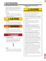
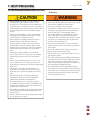
1
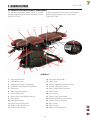
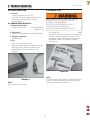
SERVICE MANUAL Model 5820- Manual Drops Model 5822- Auto Drops Applies to Serial numbers 1000 and above © 2006 Encore Medical, L.P. ISO 13485 Certified TABLE OF CONTENTS FOREWORD . .. .. .. .. .. .. .. .. .. .. .. .. .. .. .. .. .. .. .. .. .. .. .. 1 1 SAFETY PRECAUTIONS .. .. .. .. .. .. .. .. .. .. .. .. .. .. .. 2 1.1 PRECAUTIONARY DEFINITIONS .. .. .. .. .. .. .. ..2 1.2 PRECAUTIONARY INSTRUCTIONS . .. .. .. .. .. ..2 2 NOMENCLATURE . .. .. .. .. .. .. .. .. .. .. .. .. .. .. .. .. .. .. 5 2.1 ERGOSTYLE FX TABLE EXTERNAL COMPONENTS . .. .. .. .. .. .. .. .. .. .. ..5 3 SPECIFICATIONS .. .. .. .. .. .. .. .. .. .. .. .. .. .. .. .. .. .. .. 6 3.1 SPECIFICATIONS . .. .. .. .. .. .. .. .. .. .. .. .. .. .. .. .. ..6 4 TROUBLESHOOTING . .. .. .. .. .. .. .. .. .. .. .. .. .. .. .. ..7 4.1 ERGOSTYLE FX TABLE TROUBLESHOOTING .. .. .. .. .. .. .. .. .. .. .. .. .. .. ..7 4.2 VISUAL INSPECTION .. .. .. .. .. .. .. .. .. .. .. .. .. .. ..8 4.3 GROUND RESISTANCE TEST . .. .. .. .. .. .. .. .. .. ..8 4.4 LEAKAGE TESTS .. .. .. .. .. .. .. .. .. .. .. .. .. .. .. .. .. ..8 4.5 POWER ON/OFF TEST . .. .. .. .. .. .. .. .. .. .. .. .. .. ..9 4.6 PATIENT INTERRUPT SWITCH TEST .. .. .. .. .. ..9 4.7 AUTO FLEXION AND AUTO DROP TESTS . .. .. . 9 5 REMOVAL AND REPLACEMENT.. .. .. .. .. .. .. .. .. 10 5.1 POWER SUPPLY REMOVAL AND REPLACEMENT .. .. .. .. .. .. .. 10 5.2 DAUGHTER BOARD REMOVAL AND REPLACEMENT MANUAL TABLE ONLY .. 12 5.3 DRIVER BOARD REMOVAL AND REPLACEMENT .. .. .. .. .. .. .. 13 5.4 CONTROL BOARD ASSEMBLY REMOVAL AND REPLACEMENT AUTO FLEXION ONLY . .. .. .. .. .. .. .. .. .. .. .. .. 14 5.5 MOTOR REMOVAL AND REPLACEMENT.. .. 15 5.6 DROP ASSEMBLY REMOVAL AND REPLACEMENT .. .. .. .. .. .. .. 17 6- CALIBRATION .. .. .. .. .. .. .. .. .. .. .. .. .. .. .. .. .. .. .. .. ..18 6.1 FLEXION CALIBRATION AUTO TABLES ONLY.. .. .. .. .. .. .. .. .. .. .. .. .. .. 18 7 PARTS . .. .. .. .. .. .. .. .. .. .. .. .. .. .. .. .. .. .. .. .. .. .. .. .. 19 7.1 CONTROL BOARD ASSEMBLY. .. .. .. .. .. .. .. .. 19 7.2 DROPS .. .. .. .. .. .. .. .. .. .. .. .. .. .. .. .. .. .. .. .. .. .. .. 20 7.3 HEAD PIECE ASSEMBLY .. .. .. .. .. .. .. .. .. .. .. .. 21 8- SCHEMATICS . .. .. .. .. .. .. .. .. .. .. .. .. .. .. .. .. .. .. .. .. ..22 9 WARRANTY .. .. .. .. .. .. .. .. .. .. .. .. .. .. .. .. .. .. .. .. .. 27 Ergostyle ™ FX Tables FOREWORD Ergostyle ™ FX Tables Read, understand, and follow the Safety Precautions and all other information contained in this manual. This manual contains the necessary safety and field service information for those field service technicians, certified by Chattanooga Group, to perform field service on the Ergostyle FX Tables. At the time of publication, the information contained herein was current and up-to-date. However, due to continual technological improvements and increased clinical knowledge in the field of traction therapy, as well as Chattanooga Group’s policy of continual improvement, Chattanooga Group reserves the right to make periodic changes and improvements to their equipment and documentation without any obligation on the part of Chattanooga Group. It is the sole responsibility for certified field technicians to stay informed and trained in the latest technology utilized in the Ergostyle FX Tables by Chattanooga Group. From time to time, as significant improvements are incorporated, service bulletins will be produced and made available on our web site (chattgroup.com) in lieu of reprinting a complete manual prematurely. These service bulletins will provide updated service information and technological improvements to the Ergostyle FX Tables for use by certified service technicians. Due to the complex nature of the technology utilized by Chattanooga Group, the recommended troubleshooting techniques are to determine “Bad Board” and board replacement only. No board component level troubleshooting is recommended, nor will information or parts be supplied by Chattanooga Group. Any board component level troubleshooting performed will be at the sole risk and liability of the certified field service technician performing such troubleshooting techniques. Performance of such techniques may render the warranty null and void. Ergostyle FX Tables are prescription devices to be used only under the supervision of and by the order of a physician or other licensed health care provider. ©2006 Encore Medical Corporation or its affiliates, Austin, Texas, USA. Any use of editorial, pictorial, or layout composition of this publication without express written consent from the Chattanooga Group of Encore Medical, L.P. is strictly prohibited. This publication was written, illustrated, and prepared for print by the Chattanooga Group of Encore Medical, L.P. 1 1 SAFETY PRECAUTIONS Ergostyle ™ FX Tables 1.1 PRECAUTIONARY DEFINITIONS The precautionary instructions found in this section and throughout this manual are indicated by specific symbols. Understand these symbols and their definitions before operating this equipment. The definition of these symbols are as follows: 1.2 PRECAUTIONARY INSTRUCTIONS A. Cautions • Read, understand, and practice all precautionary instructions found in this manual. Know the limitations and hazards associated with use of these tables. Observe the precautionary and operational decals placed on the unit. • Do not use accessories other than those supplied with the unit or recommended by Chattanooga Group. The safety of other products has not been established, and their use could result in injury to the patient. • This unit should be transported and stored in temperatures between 0°F and 140°F (-18°C and 60°C) to prevent damage to the unit or its components. • DO NOT operate this unit in an environment where other devices are being used that intentionally radiate electromagnetic energy in an unshielded manner. Portable and mobile RF communications equipment can affect Medical Electrical Equipment. • This unit generates, uses, and can radiate radio frequency energy and, if not installed and used in accordance with the instructions, may cause harmful interference to other devices in the vicinity. However, there is no guarantee that interference will not occur in a particular installation. Harmful interference to other devices can be determined by turning this (table, unit, device, etc.) on and off. Try to correct the interference using one or more of the following: reorient or relocate the receiving device, increase the separation between the equipment, connect the equipment to an outlet on a different circuit from that which the other device(s) are connected and consult the Chattanooga Group Service Department for help. • The unit should be routinely checked before each use to determine all controls function normally. • Handle the unit with care. Inappropriate handling of the unit may adversely affect its characteristics. • Before each use, inspect the table cables and hoses for wear. Prolonged wear on these components may cause them to break, which may cause sudden release of pneumatic pressure. • Test the Patient Switch before each use for power operation. A. Caution Text with a “CAUTION” indicator will explain possible safety infractions that could have the potential to cause minor to moderate injury or damage to equipment. B. Warning Text with a “WARNING” indicator will explain possible safety infractions that will potentially cause serious injury and equipment damage. C. Danger Text with a “DANGER” indicator will explain possible safety infractions that are imminently hazardous situations that would result in death or serious injury. D. Dangerous Voltage Text with a “DANGEROUS VOLTAGE” indicator serves to inform the technician of possible hazards resulting in the electrical charge disbursement from certain components if handled or serviced improperly. E. NOTE Throughout this manual, “NOTE” may be found. These Notes are helpful information to aid in the particular area or function being described. 2 1 SAFETY PRECAUTIONS Ergostyle ™ FX Tables 1.2 PRECAUTIONARY INSTRUCTIONS (continued) B. Warnings • Never place your hands or feet near the working mechanism of the table when making any and all adjustments to height or table sections. • Use only accessories that are specially designed for the ErgoStyle FX table. Do not use accessories manufactured by other companies on the ErgoStyle FX. Chattanooga Group is not responsible for any consequence resulting from using products manufactured by other companies. The use of other accessories or cables may result in increased emissions or decreased immunity of the ErgoStyle FX. • Do not sit or allow patients to sit on the Head Section, Flexion Section, or Extending Ankle Rest of the table. • Do not lift table by Head Section or Arm Rest. • Do not smoke on or around table. • Do not allow any unsupervised patient access to the treatment table. • The table should be locked before the loading or unloading of a patient. Do not reposition or allow the patient to get on or off the table while the table is ascending/descending or if the drops are in the cocked or engaged positions. • This table should only be operated under the prescription and supervision of a licensed medical practitioner that is familiar with the precautionary measures and operational functions associated with the table being used. • Do not remove the covers. This may cause unit damage, malfunction, electrical shock, fire, or personal injury. There are no user-serviceable parts inside the unit. If a malfunction occurs, discontinue use immediately, disconnect the Mains Power Cord from the outlet, and consult the dealer for repair service. • Do not use sharp objects such as a pencil point or ballpoint pen to operate the buttons on the Control Panel as damage may result. • Do not permit any foreign materials or liquids to enter the unit. Take care to prevent any foreign materials including, but not limited to, inflammables, water, and metallic objects from entering the unit. These may cause unit damage, malfunction, electrical shock, fire, or personal injury. • Do not disassemble, modify, or remodel the unit or accessories. This may cause unit damage, malfunction, electrical shock, fire, or personal injury. • Do not use the table near devices such as X-ray units or diathermy units. These units may emit high frequency noise that may affect the operation of the unit. • Failure to use and maintain the table and its accessories in accordance with the instructions outlined in this manual will render the warranty void. • The tool, lubrication, and locking compound requirements listed are critical to component maintenance, removal and replacement. • The hardware, bolts, nuts, and screws used to assemble the Ergostyle FX are SAE. Therefore, it will be necessary to obtain SAE tools for removal and replacement of components. • The table base should never be operated in an “out of level” position to the horizontal/ground plane greater than 5°. • Always use both hands when changing the angle of any section, up or down. 3 1 SAFETY PRECAUTIONS Ergostyle ™ FX Tables 1.2 PRECAUTIONARY INSTRUCTIONS (continued) C. Dangers • DO NOT connect the unit to an electrical supply without first verifying that the power supply is the correct voltage. Incorrect voltage may cause unit damage, malfunction, electrical shock, fire, or personal injury. Your unit was constructed to operate only on the electrical voltage specified on the Voltage Rating and Serial Number Plate. Contact the Chattanooga Group dealer if the unit is not properly rated. • Power Supplies retain High Voltage! • The Ergostyle FX is a prescription device to be used only under the supervision of and by the order of a physician or other licensed health care provider. • Do not allow anything to be under the table while the table is in operation. 4 2 NOMENCLATURE Ergostyle ™ FX Tables 2.1 ERGOSTYLE FX TABLE EXTERNAL COMPONENTS The nomenclature graphics below, Figure 2.1, indicate Know the components and their functions before the general locations of the major components of the performing any operation of or service to the Ergostyle FX Table. Ergostyle FX Table. 25 24 23 22 1 21 20 19 2 3 4 18 5 6 7 8 17 16 9 11 10 12 15 13 14 26 1. 2. 3. 4. 5. 6. 7. 8. 9. 10. 11. 12. 13. FIGURE 2.1 Adjustable Ankle Rest Ankle Release Lever Autococking Controls (if applicable) Autoflexion User Interface (if applicable) Flexion Lock Pelvic Drop Cocking Lever Lateral Flexion Lever Power Supply/Control Board Housing Foot Control Fixed Glide Levelers Lumbar Drop Cocking Lever Thoracic Drop Cocking Lever Lower Frame Assembly 14. 15. 16. 17. 18. 19. 20. 21. 22. 23. 24. 25. 26. 5 Adjustable Glide Leveler Safety Covers Forward/Toggle Drop Tension Control Forward Drop Cocking Lever Head Cushion Width Adjustment Head Cushion Chest Section Thoracic Drop Tension Knob Breakaway/Elevating Chest Release Lumbar Drop Tension Knob Pelvic Section T-Bar Assembly Patient Switch Receptacle 3 SPECIFICATIONS Ergostyle ™ FX Tables 3.1 SPECIFICATIONS LENGTH HEIGHT WIDTH FIGURE 3.1 Elevation/ Tension/ Flexion Motor:. .. .. .. .. .. .. .. .. .. .. .. .. .. .. .. .. .. .. .. .. .. .. .. .. .. .. .. .. .. .. .. .. .. .. .. .. .. .. .. .. .. .. .. .. .. .. .. .. .. .. 24V DC Voltage:.. .. .. .. .. .. .. .. .. .. .. .. .. .. .. .. .. .. .. .. .. .. .. .. .. .. .. .. .. .. .. .. .. .. .. .. .. .. .. .. .. .. .. .. .. .. .. .. .. .. .. .. .. .. .. .. .. .. .. .. .. .. .. .. .. .. .. 100V-240V Tension Motor Power Supply:.. .. .. .. .. .. .. .. .. .. .. .. .. .. .. .. .. .. .. .. .. .. .. .. .. .. .. .. .. .. .. .. .. .. .. .. .. .. .. .. .. .. .Switching Power Supply Rated Frequency: .. .. .. .. .. .. .. .. .. .. .. .. .. .. .. .. .. .. .. .. .. .. .. .. .. .. .. .. .. .. .. .. .. .. .. .. .. .. .. .. .. .. .. .. .. .. .. .. .. .. .. .. .. .. .. .. .. .. .. .. .. 50/60 Hz Current:.. .. .. .. .. .. .. .. .. .. .. .. .. .. .. .. .. .. .. .. .. .. .. .. .. .. .. .. .. .. .. .. .. .. .. .. .. .. .. .. .. .. .. .. .. .. .. .. .. .. .. .. .. .. .. .. .. .. .. .. .. .. .. .. .. .. .. .. .. .. .. .. . 2A Fuses: .. .. .. .. .. .. .. .. .. .. .. .. .. .. .. .. .. .. .. .. .. .. .. .. .. .. .. .. .. .. .. .. .. .. .. .. .. .. .. .. .. .. .. .. .. .. .. .. .. .. .. .. .. .. .. .. .. .. ..T 6.3 AL 220V 5 x 20MM Lifting Capacity: .. .. .. .. .. .. .. .. .. .. .. .. .. .. .. .. .. .. .. .. .. .. .. .. .. .. .. .. .. .. .. .. .. .. .. .. .. .. .. .. .. .. .. .. .. .. .. .. .. .. .. .. .. .. .. .. .. 400 lbs. (182 kg) Shipping Weight*: . .. .. .. .. .. .. .. .. .. .. .. .. .. .. .. .. .. .. .. .. .. .. .. .. .. .. .. .. .. .. .. .. .. .. .. .. .. .. .. .. .. .. .. .. .. .. .. .. .. .. .. .. .. .. .. 440 lbs. (145 kg) Elevation/Tension Duty Cycle: . .. .. .. .. .. .. .. .. .. .. .. .. .. .. .. .. .. Intermittent-Max. 1 minute on, 9 minutes off (both motors) Flexion Motor Duty Cycle: .. .. .. .. .. .. .. .. .. .. .. .. .. .. .. .. .. .. .. .. .. .. .. .. .. .. .. .. .. .. .. .. .. .. .. .. .. .. .. .. .. .. .. .. .. .. .. .. .. .. Continuous Use Maximum Flexion Angle (Manual): .. .. .. .. .. .. .. .. .. .. .. .. .. .. .. .. .. .. .. .. .. .. .. .. .. .. .. .. .. .. .. .. .. .. .. .. .. .. .. .. .. .. .. .. .. .. .. .. .. .. .. .. .. 17° Maximum Extension Angle (Manual): . .. .. .. .. .. .. .. .. .. .. .. .. .. .. .. .. .. .. .. .. .. .. .. .. .. .. .. .. .. .. .. .. .. .. .. .. .. .. .. .. .. .. .. .. .. .. .. .. .. .. .. 14° Maximum Flexion Angle (AutoFlexion): .. .. .. .. .. .. .. .. .. .. .. .. .. .. .. .. .. .. .. .. .. .. .. .. .. .. .. .. .. .. .. .. .. .. .. .. .. .. .. .. .. .. .. .. .. .. .. .. .. .. 15° Maximum Extension Angle (AutoFlexion): .. .. .. .. .. .. .. .. .. .. .. .. .. .. .. .. .. .. .. .. .. .. .. .. .. .. .. .. .. .. .. .. .. .. .. .. .. .. .. .. .. .. .. .. .. .. .. .. 12° Side Bending:.. .. .. .. .. .. .. .. .. .. .. .. .. .. .. .. .. .. .. .. .. .. .. .. .. .. .. .. .. .. .. .. .. .. .. .. .. .. .. .. .. .. .. .. .. .. .. .. .. .. .. .. .. .. .. .. .. .. .. .. .. .. .. .. .. .. .. .. 40° AutoFlexion Speed:.. .. .. .. .. .. .. .. .. .. .. .. .. .. .. .. .. .. .. .. .. .. .. .. .. .. .. .. .. .. .. .. .. .. .. .. .. .. .. .. .. .. .. .. .. .. .. . 0.5°/second to 6.5°/second Length (Head to Toe): .. .. .. .. .. .. .. .. .. .. .. .. .. .. .. .. .. .. .. .. .. .. .. .. .. .. .. .. .. .. .. .. .. .. .. .. .. .. .. .. .. .. .. .. 69.5" - 76" (177 cm - 193 cm) Height . .. .. .. .. .. .. .. .. .. .. .. .. .. .. .. .. .. .. .. .. .. .. .. .. .. .. .. .. .. .. .. .. .. .. .. .. .. .. .. .. .. .. .. .. .. .. .. .. .. .. .. .. .. .. .. .. .. .. .. .. .19 - 32" (48 - 81 cm) Width .. .. .. .. .. .. .. .. .. .. .. .. .. .. .. .. .. .. .. .. .. .. .. .. .. .. .. .. .. .. .. .. .. .. .. .. .. .. .. .. .. .. .. .. .. .. .. .. .. .. .. .. .. .. .. .. .. .. .. .. .. .. .. .. .. .. .28.5" (72 cm) Air Compressor** (Not Provided) . .. .. .. .. .. .. .. .. .. .. .. .. .. .. .. .. .. .. .. .. .. .. .. .. .. .. .. .. .. .. 100 psi Minimum Operating Capacity Meets Directives: 93 /42 /EEC IEC/UL/EN: 60601-1 EN 60601-1-2 * Basic Table (Without Auto Flexion or Any Drops) ** Not available through Chattanooga Group. 0413 6 4 TROUBLESHOOTING Ergostyle ™ FX Tables 4.1 ERGOSTYLE FX TABLE TROUBLESHOOTING A. General- Electronic 1. Information within this section in respect to electronic components is intended to aid in troubleshooting the PCB's of the Ergostyle FX Table to “Board Level” only. These tests are the standard testing procedures and methods used at the factory before shipment of the unit. 2. Due to the complex nature of the technology utilized by Chattanooga Group, the recommended PCB troubleshooting techniques are to determine “Bad Board” and board replacement only. No PCB component level troubleshooting is recommended nor will information or parts be supplied by Chattanooga Group. Any PC board component level troubleshooting performed will be at the sole risk and liability of the Service Technician performing such troubleshooting techniques. 3. Once a particular PCB has been determined as bad, replace the PCB. Use only Chattanooga Group replacement parts and hardware. B. General- Replacement Components Critical component replacement parts for the table are available as subassemblies only. This is due to the accuracy required and the critical nature of the subassembly within the unit for power function and operation. Individual components of these subassemblies will not be made available by Chattanooga Group. C. General- Tests and Repair Procedures 1. Certain tests and repair procedures may require the use of special tools and/or fixtures. These will be listed at the particular test where they are required. Testing with any other special tool or fixture other than those stated could give erroneous readings or test results. Always perform the tests exactly as stated to ensure accurate results. 2. Test equipment settings will be listed for each test performed prior to the respective test to ensure the test is performed to Chattanooga Group standards and ensure proper readings. 3. The troubleshooting and repair of the units are to be performed only by authorized technicians trained and certified by Chattanooga Group. D. Tools, Fixtures, and Equipment Required 1. Dielectric Withstand (Hi-Pot) and ground resistance tester. NOTE: Adjust Dielectric Withstand tester to indicate fault with 120 kOhm load across the output when at specified test voltage. 2. Required Hand Tools • #2 Phillips Screwdriver • Flat Blade Screwdriver • Allen Wrenches • SAE- Allen Wrenches- 3/32" through 5/16" • End Wrenches • SAE- End Wrenches- 5/32" through 9/16" • Ground Strap for use in removal and replacement of PC Boards. • Digital Inclinometer • The hardware, bolts, nuts, and screws used to assemble the Ergostyle FX are SAE. Therefore, it will be necessary to obtain SAE tools for removal and replacement of components. • The lubricant and locking compound listed are crucial in the assembly of certain components to ensure patient safety and efficient operation of the unit. 7 4 TROUBLESHOOTING Ergostyle ™ FX Tables 4.2 VISUAL INSPECTION A. General Visually inspect the unit. A visual inspection can, to an experienced Technician, indicate possible abuse of the unit and internal problems. 4.3 GROUND RESISTANCE TEST A. Voltage Specifications Models 5820 and 5822 . . . . . . . . . Input: 100-240 VAC 50/60 Hz, 2AA B. Specification Maximum Acceptable Resistance: 100 milliohms C. Equipment Required Milliohm Meter D. Test Place unit on level work surface. Place one meter probe on the ground prong of the Mains Power Cord and the other to any exposed metal or screw on the unit. See Figure 4.1. 4.4 LEAKAGE TESTS UNIT FAILING DIELECTRIC WITHSTAND AND/OR LEAKAGE TESTS COULD INDICATE SERIOUS INTERNAL SYSTEM PROBLEMS. DO NOT PLACE UNIT BACK INTO SERVICE! CONTACT FACTORY FOR SERVICE! DO NOT ATTEMPT TO REPAIR IN THE FIELD! Test Voltage Spec . . . . . . . . . . . . . . . . . . . . . . . . . . . . . .1500 V Conduct all necessary leakage tests as required per “Chapter 7 Electrical Equipment” of the 1999, or later, edition of the NFPA (National Fire Protection Association) “Health Care Facilities” standards. See Figure 4.2. FIGURE 4.2 EXPOSED METAL GROUND PRONG NOTE: The NFPA "Health Care Facilities" standards are specific to the U.S.A. All other technicians should verify their country's requirements for these tests. FIGURE 4.1 NOTE: U.S.A. Power Cord Illustrated. 8 4 TROUBLESHOOTING Ergostyle ™ FX Tables 4.7 AUTO FLEXION AND AUTO DROP TESTS If the table is equipped with either or both of these options, verify that both features are operational by following the instructions below. A. Auto Flexion Adjust angles and speed settings on Auto Flexion to assure the Range of Motion and speeds vary accordingly. B. Auto Cocking Verify that Auto Cocking funtions. If not, check to ensure that the hoses are not pinched or kinked. 4.5 POWER ON/OFF TEST A. Specification Unit turns Off and On B. Equipment Required None C. On/Off Switch Test Procedure 1. Connect the Mains Power Cord into grounded power source with appropriate voltage. See Specifications Section. Unit should come on. 2. Turn unit Off by disconnecting Mains Power Cord from the grounded power source. D. Test Result 1. If unit turns Off and On, unit passed test. 2. If unit does not turn Off and On, unit failed test. Contact Chattanooga Group to obtain Factory Service. 4.6 PATIENT INTERRUPT SWITCH TEST A. Specification Table stops when Patient Interrupt Switch is depressed. B. Equipment Required None C. Patient Interrupt Switch Test Procedure 1. Connect Mains Power Cord into grounded power source with appropriate voltage. 2. Connect Patient Interrupt Switch to unit making certain it is completely seated in the Patient Interrupt Switch receptacle. See Figure 2.1, item 26. 3. Set up a treatment, refer to User Manual, and press the START/STOP button. 4. Press the Patient Interrupt Switch to stop the treatment. D. Test Result 1. If table stops when the Patient Interrupt Switch is depressed, unit passed test. 2. If unit does not stop, repeat test with a known good Patient Interrupt Switch. 3. If known good Patient Interrupt Switch resolves the problem, replace existing Patient Interrupt Switch with new part. 4. If the known good Patient Interrupt Switch does not remedy the problem, contact Chattanooga Group to obtain Factory Service. 9 5 REMOVAL & REPLACEMENT Ergostyle ™ FX Tables 5.1 POWER SUPPLY REMOVAL AND REPLACEMENT Unplug the unit from the power source before attempting removal or replacement procedures to prevent electrical shock. • Power Supplies retain High Voltage! POWER SUPPLY COVER A. Part Numbers Power Supply . . . . . . . . . . . . . . . . . . . . . . . . . .58516 B. Equipment Required • #2 Phillips Screwdriver C. Power Supply Removal 1. Remove the four Power Supply Cover Mounting Screws with the #2 Phillips Screwdriver. See Figure 5.1. 2. Remove the wires from the output side of the Power Supply. See Figure 5.2. 3. Remove the wires from the input side of the Power Supply. See Figure 5.3. NOTE: Make note of the wire color and locations for installation to new Power Supply. FIGURE 5.1 RED WIRE BLACK WIRE FIGURE 5.2 BROWN WIRE BLUE WIRE GREEN WITH YELLOW STRIPE WIRE FIGURE 5.3 10 5 REMOVAL & REPLACEMENT Ergostyle ™ FX Tables 5.1 POWER SUPPLY REMOVAL AND REPLACEMENT continued) Unplug the unit from the power source before attempting removal or replacement procedures to prevent electrical shock. • Power Supplies retain High Voltage! 3. Tilt the table so that access to the Power Supply Mounting Screws can be obtained. Remove the four Power Supply Mounting Screws using the #2 Phillips Screwdriver. See Figure 5.4. D. Replacing Power Supply Replace in reverse order of removal. Refer to Figures 5.2 and 5.3 for wire installation. POWER SUPPLY MOUNTING SCREWS FIGURE 5.4 11 5 REMOVAL & REPLACEMENT Ergostyle ™ FX Tables 5.2 DAUGHTER BOARD REMOVAL AND REPLACEMENT MANUAL TABLE ONLY Unplug the unit from the power source before attempting removal or replacement procedures to prevent electrical shock. A. Part Numbers Daughter Board . . . . . . . . . . . . . . . . . . . . . . .58543 B. Equipment Required • #2 Phillips Screwdriver • Ground Strap C. Daughter Board Removal 1. Put Ground Strap on to prevent damage to the Daughter Board through static. 2. Remove the four Power Supply Cover Mounting Screws with the #2 Phillips Screwdriver. See Figure 5.5. 3. Remove connector and two mounting screws from Daughter Board. See Figure 5.6. 4. Carefully lift the Daughter Board from the Driver Board. See Figure 5.7. D. Replacing Daughter Board Replace Daughter Board in reverse order of removal. POWER SUPPLY COVER FIGURE 5.5 MOUNTING SCREWS CONNECTOR FIGURE 5.6 FIGURE 5.7 12 5 REMOVAL & REPLACEMENT Ergostyle ™ FX Tables 5.3 DRIVER BOARD REMOVAL AND REPLACEMENT Unplug the unit from the power source before attempting removal or replacement procedures to prevent electrical shock. A. Part Numbers Driver Board . . . . . . . . . . . . . . . . . . . . . . . . . . .58432 B. Equipment Required • #2 Phillips Screwdriver • 1/4" End Wrench • Ground Strap C. Driver Board Removal NOTE: It will be necessary to remove the Daughter Board before removal of the Driver Board on Manual Tables. Refer to 5.2 Daughter Board Removal and Replacement. POWER SUPPLY COVER FIGURE 5.8 1. Put Ground Strap on to prevent damage to the Driver Board through static. 2. Remove the four Power Supply Cover Mounting Screws with the #2 Phillips Screwdriver. See Figure 5.8. 3. Remove all harnesses and connectors from the Driver Board. See Figure 5.9. 4. Remove the three standoffs and one screw retaining the Driver Board. D. Driver Board Replacement Replace Driver Board in reverse order of removal. FIGURE 5.9 13 5 REMOVAL & REPLACEMENT Ergostyle ™ FX Tables 5.4 CONTROL BOARD ASSEMBLY REMOVAL AND REPLACEMENT AUTO FLEXION ONLY Unplug the unit from the power source before attempting removal or replacement procedures to prevent electrical shock. A. Part Numbers Control Board Assembly . . . . . . . . . . . . . .58554 B. Equipment Required • #2 Phillips Screwdriver • 3/8" and 7/16" End Wrenches • Ground Strap C. Control Board Assembly Removal 1. Put Ground Strap on to prevent damage to the Control Board through static. 2. Remove the Front Panel of the Control Housing. See Figure 5.10. 3. Remove the four Control Board Mounting Screws securing the Control Board to the housing. 4. Remove all harnesses and connectors from the Control Board. D. Control Board Assembly Replacement Replace Control Board in reverse order of removal. FRONT PANEL MOUNTING SCREWS FIGURE 5.10 14 5 REMOVAL & REPLACEMENT Ergostyle ™ FX Tables 5.5 MOTOR REMOVAL AND REPLACEMENT Unplug the unit from the power source before attempting removal or replacement procedures to prevent electrical shock. A. Part Numbers Motor . . . . . . . . . . . . . . . . . . . . . . . . . . . . . . . . . .58366 B. Equipment Required • #2 Phillips Screwdriver • 3/16" Allen Wrench • 1/2" End Wrench C. Motor Removal 1. Position the Flexion end of the table in the Up position as shown in Figure 5.11 to remove all possible tension from the spring mechanism. 2. Raise or remove the cushion to allow access to the motor mounting hardware. 3. Remove the four Power Supply Cover Mounting Screws with the #2 Phillips Screwdriver. See Figure 5.12. 4. Disconnect the Motor Connector from the Driver Board Tension Connector. See Figure 5.13. 5. Remove Motor Cable from the Power Supply Cover. Keep grommet for re-installation. RAISE UP AND LOCK INTO POSITION FIGURE 5.11 POWER SUPPLY COVER FIGURE 5.12 TENSION CONNECTOR FIGURE 5.13 15 5 REMOVAL & REPLACEMENT Ergostyle ™ FX Tables 5.5 MOTOR REMOVAL AND REPLACEMENT continued) 6. Remove the Motor Mounting Hardware from the Motor Base and Rod. See Figure 5.14. MOTOR MOUNTING HARDWARE D. Motor Replacement Replace Motor in reverse order of removal. FIGURE 5.14 16 5 REMOVAL & REPLACEMENT Ergostyle ™ FX Tables 5.6 DROP ASSEMBLY REMOVAL AND REPLACEMENT REMOVE APPROPRIATE CUSHION Unplug the unit from the power source before attempting removal or replacement procedures to prevent electrical shock. A. Part Numbers Appropriate Drop . . .Refer to Section 7- Parts B. Equipment Required • #2 Phillips Screwdriver • 3/16" Allen Wrench • 1/2" End Wrench C. Drop Assembly Removal 1. Remove appropriate cushion for the drop that is to be replaced. See Figure 5.15. NOTE: If replacing a Drop on an Auto Drop Table, perform step 2 first. If replacing a Drop on a Manual Drop Table go to step 3. 2. Remove the four screws from top of the Pneumatic Cylinder. See Figure 5.16. 3. Remove the hardware securing the Drop Assembly to the frame. See Figure 5.17. D. Drop Assembly Replacement Replace Drop Assembly" reverse order of removal. FIGURE 5.15 PNEUMATIC CYLINDER HARDWARE FIGURE 5.16 DROP HARDWARE FIGURE 5.17 17 6 CALIBRATION Ergostyle ™ FX Tables 6.1 FLEXION CALIBRATION AUTO FLEXION TABLES ONLY A. Specification Inclinometer dependent B. Equipment Required Calibrated Digital Inclinometer with an accuracy of ±0.50°. C. Calibration Procedure NOTE: Two people are required to perform this procedure. 1. Make certain the FX Table Base Frame is level. 2. Depress and hold the Up and Down Arrow buttons while connecting AC power to the table. See Figure 6.1. 3. Release Up and Down Arrow buttons. Unit will start in Calibration Mode. Display will read; "Move table to -13 degrees then press start". 4. Zero the Digital Inclinometer on the lower frame of the table. 5. Raise the hinged Pelvic Cushion and place the Digital Inclinometer on the Pelvic Section Frame. 6. Release the Flexion Lock and manually adjust the Flexion Angle up until the Digital Inclinometer reads 13 degrees. If 13 degrees cannot be obtained, raise the Pelvic Section to the mechanical limit. Manually hold the Pelvic Section in position. 7. Press the START/STOP button. 8. When the display reads "Move Table to +16 then press start", manually adjust the Flexion Angle down until the Digital Inclinometer reads -16.0 degrees. If -16 degrees cannot be obtianed, lower the Pelvic Section to the mechanical limit. Manually hold the Pelvic Section in position. 9. Press the START/STOP button. The table is now calibrated and the display will change to the normal operation mode. 10. Disconnect unit from AC power source. 11. Reconnect unit to AC power source and visually verify the the Control Panel is displaying the normal operating mode menu. 12. Press the START/STOP button to begin a treatment. Compare the angle readings from the display with the Digital Inclinometer. The readings on the Digital Inclinometer should be the same as the display ±2°. FIGURE 6.1 18 7 PARTS Ergostyle ™ FX Tables 7.1 CONTROL BOARD ASSEMBLY 1 ITEM PART NO. 1 58554 DESCRIPTION Control Board Assembly QTY 1 19 7 PARTS Ergostyle ™ FX Tables 7.2 DROPS 1 2 ITEM PART NO. DESCRIPTION 1 95544 Lumbar and Pelvic Drop Assembly 1 2 95524 Thoracic Drop Assembly 1 20 QTY 7 PARTS Ergostyle ™ FX Tables 7.3 HEAD PIECE ASSEMBLY 1 NOTE: Cushions must be replaced in pairs. ITEM PART NO. DESCRIPTION 1 58474 Head Piece- Tilt, ±20°, Fixed Cushions (Standard) - 58476 Head Piece- Tilt, ±20°, Adjustable Cushions 1 - 58475 Head Piece- Tilt, ±20°, Forward and Toggle Drop, Adjustable Cushions 1 - 58473 Head Piece- Tilt, ±20°, 9" (23cm) Elevation, Adjustable Cushions 1 - 58472 Head Piece- Tilt, ±20°, 9" (23cm) Elevation, Forward and Toggle Drop, Adjustable Cushions 1 21 QTY 1 Ergostyle ™ FX Tables 8 SCHEMATICS Block Diagram 1 of 1 22 Ergostyle ™ FX Tables 8 SCHEMATICS Pneumatic 1 of 1 23 Ergostyle ™ FX Tables 8 SCHEMATICS Driver Board- 58432 1 of 1 24 Ergostyle ™ FX Tables 8 SCHEMATICS Control Board-58433 1 of 1 25 Ergostyle ™ FX Tables 8 SCHEMATICS Daughter Board- 58543 1 of 1 26 Ergostyle ™ FX Tables 9 WARRANTY UNITED STATES OF AMERICA, CANADA AND PUERTO RICO Chattanooga Group (“Company”) warrants that the ErgoStyle FX Table (“Product”) is free of defects in material and workmanship. This warranty shall remain in effect for one year (12 months) from the date of original consumer purchase. If this Product fails to function during the one year warranty period due to a defect in material or workmanship, Company or the selling dealer will repair or replace this Product without charge within a period of thirty days from the date on which the Product is returned to the Company or the dealer. All repairs to the Product must be performed by a service center authorized by the Company. Any modifications or repairs performed by unauthorized centers or groups will void this warranty. This Warranty Does Not Cover: • Replacement parts or labor furnished by anyone other than the Company, the selling dealer, or a service technician certified by the Company. • Defects or damage caused by labor furnished by someone other than Company, the selling dealer, or a certified Company service technician. • Any malfunction or failure in the Product caused by product misuse, including, but not limited to, the failure to provide reasonable and required maintenance or any use that is inconsistent with the Product User’s Manual. COMPANY SHALL NOT BE LIABLE IN ANY EVENT FOR INCIDENTAL OR CONSEQUENTIAL DAMAGES. Some locations do not allow the exclusion or limitation of incidental or consequential damages, so the above limitation or exclusion may not apply to you. To obtain service from Company or the selling dealer under this warranty: 1. A written claim must be made within the warranty period to the Company or the selling dealer. Written claims made to the Company should be sent to: Chattanooga Group 4717 Adams Road Hixson, TN 37343 USA Phone: (423) 870-2281 Service Phone: +1-800-494-3395 FAX: (423) 875-5497 and 2. The Product must be returned to the Company or the selling dealer by the owner. This warranty gives you specific, legal rights and you may also have other rights which vary from location to location. The Company does not authorize any person or representative to create for it any other obligation or liability in connection with the sale of the Product. Any representation or agreement not contained in the warranty shall be void and of no effect. THE FOREGOING WARRANTY IS IN LIEU OF ALL OTHER WARRANTIES, EXPRESSED OR IMPLIED, INCLUDING ANY WARRANTY OR MERCHANTABILITY OR FITNESS FOR A PARTICULAR PURPOSE. 27 9 WARRANTY Ergostyle ™ FX Tables INTERNATIONAL Chattanooga Group (“Company”) warrants that the ErgoStyle FX Table (“Product”) is free of defects in material and workmanship. This warranty shall remain in effect for two years (24 months) from the date of original consumer purchase. If this Product fails to function during the two year warranty period due to a defect in material or workmanship, Company or the selling dealer will repair or replace this Product without charge within a period of thirty days from the date on which the Product is returned to the Company or the dealer. All repairs to the Product must be performed by a service center authorized by the Company. Any modifications or repairs performed by unauthorized centers or groups will void this warranty. This Warranty Does Not Cover: • Replacement parts or labor furnished by anyone other than the Company, the selling dealer, or a service technician certified by the Company. • Defects or damage caused by labor furnished by someone other than Company, the selling dealer, or a certified Company service technician. • Any malfunction or failure in the Product caused by product misuse, including, but not limited to, the failure to provide reasonable and required maintenance or any use that is inconsistent with the Product User’s Manual. COMPANY SHALL NOT BE LIABLE IN ANY EVENT FOR INCIDENTAL OR CONSEQUENTIAL DAMAGES. Some locations do not allow the exclusion or limitation of incidental or consequential damages, so the above limitation or exclusion may not apply to you. To obtain service from Company or the selling dealer under this warranty: 1. A written claim must be made within the warranty period to the Company or the selling dealer. Written claims made to the Company should be sent to: Chattanooga Group 4717 Adams Road Hixson, TN 37343 USA Phone: +1-423-870-7200 FAX: +1-423-870-2046 and 2. The Product must be returned to the Company or the selling dealer by the owner. This warranty gives you specific, legal rights and you may also have other rights which vary from location to location. The Company does not authorize any person or representative to create for it any other obligation or liability in connection with the sale of the Product. Any representation or agreement not contained in the warranty shall be void and of no effect. THE FOREGOING WARRANTY IS IN LIEU OF ALL OTHER WARRANTIES, EXPRESSED OR IMPLIED, INCLUDING ANY WARRANTY OR MERCHANTABILITY OR FITNESS FOR A PARTICULAR PURPOSE. 28 ISO 13485 Certified 4717 Adams Road P.O. Box 489 Hixson, TN 37343 U.S.A. 1-423-870-2281 1-800-592-7329 U.S.A. 1-800-361-6661 CANADA +1-423-870-7200 OUTSIDE U.S.A +1 423-870-2046 OUTSIDE U.S.A. FAX chattgroup.com Medical Device Safety Service (MDSS) Burckhardtstr. 1 D-30163 Hannover Germany Telephone: +49-5103-939430 © 2006 Encore Medical, L.P. 58558A 0413