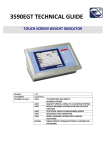
1
DigiCreaser
HAND FED DOCUMENT
CREASING MACHINE
SERVICE MANUAL
Morgana Systems Limited United Kingdom
Telephone: ( 01908 ) 608888 Facsimile: ( 01908 ) 692399
Website: www.morgana.co.uk
ISSUE 4
OCTOBER 2012
70-088
INTRODUCTION
MORGANA DigiCreaser
i ...........Introduction
The purpose of this manual is to explain the procedure for dismantling and re-assembly of the major assemblies on the Morgana
Digicreaser.
All the engineering adjustments are shown at the end of each
relevant section.
Operator's adjustments and routine maintenance are explained in
the appropriate operators guide which should always be used in
conjunction with this manual.
It is always a good idea to have a copy of the machines illustrated
parts manual available when servicing, as its illustrations provide
an invaluable reference to the construction of the individual
assemblies used to build the machine.
ii ..........Fasteners
All threaded fasteners are isometric & all nuts are isometric
hexagon. All screws are hardened high tensile steel.
Cap head, Button head, Socket countersunk, Shoulder bolts and
Grubscrews have internal hexagon drives which require isometric
hexagon wrenches (allen keys). Ball drivers may be used, but care
should be taken—particularly when releasing screws for
dismantling—to avoid breaking the driver as they cannot cope with
full tightening torques.
NOTE ..... Do not substitute fasteners with low grade alternatives
which may fail or become irremovable.
Page 2
HAND FED CREASING
DigiCreaser
INTRODUCTION
Pan head and Cross-head countersunk screws all have metric
Taptite threads and Pozi -drive recesses. Use No.2 point Pozidriv
or Supadriv drivers for all screws M4 & above, and No.1 point
drivers for M3 & below.
WARNING
WORK SHOULD BE CARRIED OUT BY A TRAINED AND
COMPETENT
ENGINEER
AND
ALL
SAFETY
PROCEDURES SHOULD BE ADHERED TO.
SWITH OFF MAINS POWER BEFORE COMMENCING
DO NOT USE PHILLIPS DRIVERS - THESE WILL DAMAGE
THE SCREWS & MAY SLIP, CAUSING DAMAGE OR
INJURY.
iii ........ Identification
For general identification of areas of the machines, the following
terms are used:Operator side (control panel facing)
Rear of machine (opposite to control panel)
Delivery end (to the left of the operator side)
Feeder end ( on your right )
iv ........ New Machine Preparation
Remove all packaging materials
All metal parts, including the folding rollers have a protective
coating and any excess should be removed.
Connect the power cable to the mains supply. The machine
requires 230V 50Hz 10 Amps or 115 60Hz 15 Amps.
SYSTEM
Page 3
INDEX
Introduction………………………………………………………………………….
¡
Introduction
¡¡
Fasteners
¡¡¡
Identification
iv
New Machine Preparation
Section 1…… Covers………….…. .................................................................
Section 2 ……Main Creaser Mechanism .......................................................
Removal of Unit
Section 3…….Removal /Replacement Stepper Drive Belt / Pulleys …………
Section 4…….Infeed Roller Removal/Replacement……………………………
Section 5…….Drive Hub - Replace Rubber Torsion Bush (shock absorber)
Section 6…….Drive Link Refurbishment…….…………………………………...
.
Section 7…….Electrics………..…………………………………………………...
Removal/Refitting PCBs
Replacement of Joystick Controller
Diagnostics
Setting the Measurement System (Metric / Inch)
Setting the Language (English, French, German)
Digicreaser Wiring Diagram
Digicreaser Control PCB Connection Diagram
Section 8 …..Optical Sensors…….……………………………………………..
Section 9 …...Trouble Shooting…………………………………………………
Calibration of Creasing Position
Trouble Shooting
Fuse Positions and Ratings
Page 4
HAND FED CREASING
DigiCreaser
DigiCreaser
HAND FED DOCUMENT CREASING MACHINE
Key to photograph below
1
2
3
4
Roller tilt handle
Stacker assembly
The display unit
Adjustable side lay
SYSTEM
5
6
7
8
Back stop RH
Fixed side lay
Roller tilt knob
Exit Guard
9
10
11
12
13
Control Panel
Fuses
Stacker Guide LH
Stacker Guide RH
Back Stop LH
Page 5
SECTION 1
1.1 The Feed Table.
To remove the feed table first remove the four M6 button head screws and washers.
The feed table can now be slid off after removing the display unit .
1.2 The Frame Assembly.
To remove the frame assembly first remove the three M4 screws along the bottom edge of the frame,
under the mains input connector.
Remove the two M6 screws, nuts and washers at the bottom of the frame, at the back and front
of the machine next to the creaser mechanism.
Remove the two pillars at the top of the frame, at the back and front of the machine next to the
creaser mechanism.
Unplug all the connectors from the PCBs and disconnect the wires.
The frame assembly can now be carefully removed.
1.3 The Creaser Mechanism Cover.
The creaser mechanism is situated towards the delivery end of the machine and is covered by
a fixed and a hinged guard.
To remove these guards just remove the four screws (M4 x 8 long) beneath the infeed guard.
Pull off the rubber handle from the tilt lever, the infeed guard can now be lifted upwards and
removed.
Page 6
HAND FED CREASING
DigiCreaser
SECTION 2
MAIN CREASER MECHANISM
REMOVAL OF UNIT
2.1
First access should be gained by removing the top infeed and outfeed guards
(See Section 1)
2.2
Remove the feed table and display unit.
2.3
Detach guard micro switch by removing two screws, taking care not to drop them.
2.4
Cut and remove cable ties from cable mounting, retaining wiring loom.
Ensure that the mains is unplugged.
2.5
From the rear of the machine, remove two button socket screws with their
washers.
2.6
Remove the ’unlock’ knob from the front of the machine.
2.7
The unit can be lifted by two people vertically out of the frame with care.
One person should be guiding the wiring and plugs to ensure they do not get
trapped during the lifting.
SYSTEM
Page 7
2.8
Place the unit on a solid and clear bench ensuring no wires are trapped beneath
the metal side plates.
2.9 Replace the unit ensuring the wiring harness is threaded as it was removed
2.10 Fit the tilt lever to the inside front frame with the bottom button head and screw
in tilt knob.
2.11 Slide rear spacer bar down in position (see below). Fix the bottom screw in and
align the top screw and fit loosely. Replace cable ties to mountings. Align the
roller set square with the fixed lay edge while the front tilt lever is in the centre
position. (Use the rear slots to adjust square) Tighten the screws and replace
the top covers.
Page 8
HAND FED CREASING
DigiCreaser
SECTION 3
REMOVAL/REPLACEMENT
PULLEYS
STEPPER
DRIVE
BELT/
3.1
Loosen the adjuster nut from the inside unit and slide the belt off.
3.2
Loosen the securing socket set screws in the drive pulley on the roller for it
to be removed (NOTE there is one screw located in a hole in the shaft)
3.3
Refitting the belt is a reverse procedure. To tighten the belt, first adjust the drive
motor down to allow ‘feel’ of belt tightness; then re-adjust the motor / gear mesh
to allow minimum backlash.
SYSTEM
Page 9
SECTION 4
REMOVAL / REPLACEMENT OF INFEED ROLLLER.
4.1
With the unit on a bench.
4.2
Remove the drive belt and pulley from the roller to be removed.
(See section 3)
WORKING ON THE DRIVE BELT SIDE:
4.3
Remove the three M4 posi-head taptite screws from around the bearing hole
in the side plate (Drive belt side) to allow easy access to the bearing retaining
rings. Remove the rings.
4.4
Slide the roller out and remove the bearing from the shaft drive belt side.
The roller can be turned sideways to allow removal.
Note the position of the spring washers.
4.5
Replace the roller in the reverse manner.
Page 10
HAND FED CREASING
DigiCreaser
SECTION 5
DRIVE HUB:- REPLACE RUBBER TORSION BUSH (SHOCK
ABSORBER).
5.1 Loosen grub screws in one half of hub.
5.2
Slide hub outward & remove rubber torsion bush.
5.3
Replace in reverse order.
Rubber Torsion Bush
SYSTEM
Page 11
SECTION 6
DRIVE LINK REFURBISHMENT
6.1 Remove the drip tray by removing the four securing screws fixed to the tie bars.
6.2 Remove both tie bars and drip tray.
6.3 Remove the micro switch assembly to gain access to the rear drive link.
6.4 Using a short dumpy posi drive screwdriver, unscrew the three screws from the side
of the link plate. Slide the side off (‘O’ Rings should be maintained in position).
The plastic drive link can be removed by sliding it forward.
6.5 Replace the drive link and outer plate.
6.6 Re-assemble in reverse order.
Link Plate
Page 12
Micro Switch Assembly
HAND FED CREASING
DigiCreaser
SECTION 7
ELECTRICS: REMOVAL / REFITTING PCB / POWER SUPPLY ASSEMBLY
All the Electric controls and pcbs are located within the frame.
Disconnect the mains.
Remove the feed table and display unit.
Unplug all plugs from the PCBs and disconnect wires.
The total electronics assembly can be removed from the machine by unscrewing the four
fixings. on the frame. (two screws at the bottom and two spacers at the top).
POWER SUPPLY ASSEMBLY- Two Large PSU
The two large PSU’s are located, mounted on a plate fitted within the frame, to remove these
Follow the steps below.
Using a 4mm socket with extension bar, remove the six nuts from the studs and lift clear
of the m/c. Removal of individual PSU is by removal of two countersunk screws in the rear
of the plate.
Replace the units using the same screws, as damage will occur if longer screws are used.
POWER SUPPLY- Small PSU 5/24V dc
First remove the PSU assembly as above, this will give you access to the four posi pan head
screws fixing the unit to the inside of the frame.
BOARD REPLACEMENT. STEPPER DRIVE PCB
The Stepper Driver board supplies the power to both Blade motor and main Drive motor and
can be removed whilst located on the machine.
Switch the mains power off.
Cut cable ties and unplug the four green plugs.
Take note of the two spade terminals on each board and remove.
Unscrew the five fixing screws attaching the board to the frame and remove from the machine.
Refitting is a reverse procedure to the above.
IMPORTANT:Check that the switch positions on SW1, SW2, SW3, and SW4 are correct, see wiring diagram.
.
SYSTEM
Page 13
Replacing the Joystick Controller
Located on the leg, this switch is an assembly made up of four micro switches and an
encoder which are generally very reliable once installed. Should it require replacing
follow the procedure below.
1. Remove the feed table and display unit, giving access to the yellow leg, the
the PCBs and the power supplies.
2. The switch is fitted to the leg with four M2.5 socket head screws, one on each
corner, which can only be accessed from the inside of the frame. Undo the four
screws and unplug the 5 way and 3 way green plugs from the main control
board located at the rear of the machine.
3. Remove the switch and lead taking note of the route taken by the cable and the
relevant cable tie positions.
4. Refitting is generally the reverse procedure but note, the cable clamping screw
on the body of the joystick must be at the top as shown below.
5. Fix the cable using the same path and fixing points and plug the 5 way and 3
way green connectors into the p.c.b.
CABLE CLAMPING SCREW
JOYSTICK CONTROLLER
Page 14
HAND FED CREASING
DigiCreaser
DIAGNOSTICS.
To set total counter to zero.
Turn the Machine on.
Insert the Engineers Plug into the Socket located at the rear of the machine.
Select Tools on the Display and scroll down the screen until ‘M/C TotalX10’ and a numeric value is
between the Arrows. (Take note of this figure)
Operate the Joystick to reset count to zero.
Lift the joystick up until the start screen appears.
NOTE. This also removes all stored programmes,
including the ‘Lead Edge Trim’ and ‘Stretch’ settings.
SET THE MEASUREMENT SYSTEM (METRIC / IMPERIAL SETTINGS).
To set the measurement system for Imperial (Inch) or Metric (mm) the following procedure is necessary.
Turn the machine on.
Insert the Engineers Plug into the Socket located at the rear of the machine.
Select Tools on the Display and scroll down the screen until
‘METRIC or IMPERIAL’ is displayed.
Operate the Joystick to change the selection.
Lift the joystick up until the start screen appears.
SET THE LANGUAGE (ENGLISH, FRENCH, GERMAN)
To set the language.
Turn the machine on.
Insert the Engineers Plug into the Socket located at the rear of the machine.
Select ,Tools’ on the Display and scroll down the screen until ‘English’, ‘Francais’, or ‘Deutsch is
displayed.
Operate the joystick to change to the required language.
Remove the Engineers Plug.
SYSTEM
Page 15
Page 16
HAND FED CREASING
EARTH LEAD 75-281
BRN
BL
BL
RED
BRN
GRN/YEL
BL
RED
BRN
DigiCreaser
2
3
4
6
7
8
9
11
12
13
24
49
75-210-05
JOYSTICK
JOYSTICK
PSU OUTPUT LEAD (75-303)
DRIVE STEPPER (75-268)
BLADE STEPPER 1 (75-267)
SYSTEM SWITCH COIL LEAD (75-185)
GUARD (76-171)
BLADE HOME (76-170)
CRANK ROTATION (76-169)
EDGE TX (76-168)
EDGE RX/JAM TX (76-167)
JAM RX (76-166)
ENGINEERING (75-255)
JOYSTICK ASSY. (144-04-04)
DISPLAY
RD
CRUNCH
YLW
RD
SCR
BL
GRN
GRN
YLW
ENGINEERING
EDGE
GRN
RD
4
BL
YLW
11
BLK
YLW
GRN
BL
BLADE
BLADE STEPPER
8
HOME
GRN
RD
3
BL
YLW
BLK
WHI
DRIVE STEPPER
BRN
BRN
BL
BL
GUARD
2
PSU
GRN
DOUBLE
AIR
75-261
CONTROL BOARD MK3
DIGICREASER
CONTROL PCB
CONNECTION DIAGRAM
SYSTEM
SHEET 1 OF 2
Page 17
Page 18
HAND FED CREASING
DigiCreaser
SECTION 8
Cleaning Sensors
With blades removed the optical sensors are accessible for cleaning on either side of the
creaser unit - use a soft brush or cloth to remove any dust that may of collected onto
sensor lens.
SYSTEM
Page 19
SECTION 9 Trouble Shooting
Calibration of creasing position
The length between the leading edge of the sheet and the 1st crease position can be
calibrated in the event of the machine creasing out of position.
Also the last crease closest to the back of the sheet can be adjusted relative to the front
edge of the sheet to compensate for the inaccuracy of manufacture of the input roller
diameters.
The first crease should be 50 mm from the lead edge (less than 1 revolution of the infeed roller) & the last crease should be 370 mm from the lead edge.
Adjust the 1st crease position as follows:Turn On machine.
Insert the Engineers Plug into the Socket located at the rear of the machine.
Run the machine and measure the first crease position at 50 mm.
Select Tools on the Display and scroll down the screen until
‘LEAD EDGE TRIM’ and a numeric value is between the Arrows.
Operate the Joystick to change the value (Left to Increase), a higher value
Will move the crease further from the lead edge. (0 is a good start value)
Lift the joystick up until the start screen appears.
Run machine and check crease position, repeat above procedure until accurate
crease position is achieved.
Adjust the Last crease position as follows:Turn On machine.
Insert the Engineers Plug into the Socket located at the rear of the machine.
Run the machine and measure the last crease position at 370 mm.
Select Tools on the Display and scroll down the screen until
‘STRETCH’ and a numeric value is between the Arrows.
Operate the Joystick to change the value (Left to Increase), a higher value
will move the crease further from the lead edge. (0 is a good start value)
Lift the joystick up until the start screen appears.
Run machine and check crease position, repeat above procedure until accurate
crease position is achieved.
Page 20
HAND FED CREASING
DigiCreaser
Section 9 Trouble Shooting
Fault
Reason
Erratic register of
the Creaser
No Power
or No Display
Display shows Faint
or unrecognizable
characters
No Display
No Control of Menu
Damaged roller surface
Faulty motor
Fuse Blown
Check small Power supply
input on CN1
Solution
Replace rubber rollers
Remove and replace motor assembly.
Check small power supply output
Voltage on Cn2 =5V dc
Replace with correct value.
L & N Voltages should read 240V or 110V AC
Check cables for continuity to
Emergency stop button.
Replace Faulty wire or connection.
Black lead of meter to green wire.
Red lead of meter to blue wire.
If supply has input but no output.
Check voltage on main
PCB CN6
Replace PSU
If no voltage then check for damaged
wire or connection. Replace as required.
Check ribbon cable for
Change Display PCB or Assembly.
damage
communication fault or
Replace main PCB
faulty processor.
If LED1 & LED2 are lit on main PCB.
Adjust VR1 (contrast)
Check CN4 is correctly fitted
Adjust VR2 (backlit)
If still no display
Change Display PCB or Assembly.
If missing lines
Change Display PCB or Assembly.
Check Joystick wires
Check Joystick
Repair damaged wires or Replace Joystick assembly
Switch m/c off. Black lead of meter to blue wire small PSU.
Red lead of meter to each terminal CN10 (main PCB)
First 4 pins will show reading of 4.7 Kohms
Move joystick 4 posn. Check all pins.
If any pins show 4.7 K ohms without moving joystick
Suspect a fault joystick and replace the assembly.
No Drive or Motors Pulsing Low or No Power Check green light is illuminated on both PSUs
to Motors
Check 240/110V AC input to Large PSUs
( Meter across L & N terminals)
No LED on Stepper PCB Low or No Power
Meter across V+ & V- of SP-150-24 reading 24V dc
from PSU
Meter across V+ & V- of SP-150-48 reading 48V dc
Replace PSU if no or low reading
Meter across V+ of SP-150-48 & V- of SP-150-24 reading 72V dc
If voltage is correct but no light on stepper then check cable integrity.
If Motors Run but Display Shows Check Lead No3
Check white & black wire for continuity.
Operate System Switch
from CN4 (bottom plug)
Before Running’.
of Stepper to Cn2 of
Main PCB.
SYSTEM
Page 21
Section 9 Trouble Shooting
Fault
Reason
Solution
If Motors Run but Display Shows Check connectors
‘Operate System Switch Before
Running’.
If System switch activates
faulty cable
but display shows
or terminals
‘Activate System Switch
Before Running’.
To Check. 5Vdc should be across pins 5 & 6 on CN2
Main PCB when System Switch is operated.
Check 6 core cable
from CN2 of control board
to CN4 of stepper board
Motors Erratic
Wrongly wired
Incorrect voltage
Should read approx
30vdc When running
Check colours with wiring diagram.
Black lead of meter on tab IC13 (Stepper PCB)
Red lead of meter on each pin CN3 (drive)
Red lead of meter on each pin CN2 (Blade)
Sensor - Transmitter
Check supply voltage
Black lead of meter on tab IC8 (Main PCB)
Should read 1.3Vdc
Red lead of meter on red wire of CN8
(Closest red wire to CN3) And also yellow wire of CN12
To Adjust these voltages Adjust VR3 Edge sensor & VR5 Jam sensor.
Sensor - Receiver, Jam
Check voltage 2.9Vdc
Meter across Red/Black of CN12 (Obstruct
Beam and Voltage will rise to approx 5 Vdc)
Voltage will increase/decrease by adjusting intensity of transmitter (pot VR5)
Sensor - Receiver, Edge
Check voltage 0.466Vdc Meter across Red/Blue of CN8(Obstruct
Beam and Voltage will rise to approx 5 Vdc)
Note- Voltage will increase/decrease by adjusting intensity of transmitter
(Pot VR3 or VR4 depending on SW1 switch position)
Safety Circuit Faulty
No Drive.
Check Voltage on
CN7 =11/12 Vdc
To Check PCB.
To Check Cable
Any Switch or Wire, Open circuit will be 0Vdc
Black lead of meter on tab IC8 (Main PCB) Red lead of
meter on brown wire plug6 CN7 should read 12Vdc
Unplug CN7 (meter set to Ohms) place probes
across plug If no continuity then check each switch.
Error Double Sheet
Detected
Check link on CN11 is correct.
Slot Sensor Blade
CN3
Home Position Switch
Page 22
Remove plug from CN13
Replace link, check wiring diagram.
Black lead of meter on Yellow (ground)
Red lead of meter on Green = 0.2Vdc obstructed
Approx 4Vdc not obstructed.
Red lead of meter on Blue = 5Vdc
Red lead of meter on Red = 1.2Vdc
Check continuity across wires (make and break switch)
HAND FED CREASING
DigiCreaser
FUSE POSITIONS & RATINGS
PSU (5V / 24V)
T4.0A (681-015)
SPARE FUSE
POSITION
PSU (24V & 48V)
T4.0A (681-015)
SPARE FUSE
POSITION
SYSTEM
Page 23