1
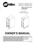
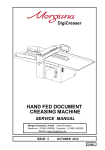
FOLDING SYSTEM
SERVICE MANUAL
Morgana Systems Limited
Snowdon Drive
WinterHill
Milton Keynes
Buckinghamshire
MK6 1AP
United
Kingdom Telephone: ( 0908 ) 608888
Facsimile:
ISSUE 2 MARCH 2002
625-030
INTRODUCTION
SERVICE
FOLDING SYSTEMS
i ...........Introduction
The purpose of this manual is to explain the procedure for dismantling and re-assembly of the major assemblies on both the
Folding and Cross Folding machines.
All the engineering adjustments are shown at the end of each
relevant section.
Operator's adjustments and routine maintenance are explained in
the appropriate operators guide which should always be used in
conjunction with this manual.
It is always a good idea to have a copy of the machines illustrated
parts manual available when servicing, as its illustrations provide
an invaluable reference to the construction of the individual
assemblies used to build the machine.
ii ..........Fasteners
Most of the pulleys on the machines use dog-point screws, which
engage in holes in the shafts to ensure reliable drive. They must be
fully withdrawn prior to dismantling.
All threaded fasteners are isometric & all nuts are isometric
hexagon. All screws are hardened high tensile steel.
Cap head, Button head, Socket countersunk, Shoulder bolts and
Grubscrews have internal hexagon drives which require isometric
hexagon wrenches (allen keys). Ball drivers may be used, but care
should be taken -particularly when releasing screws for
dismantling- to avoid breaking the driver as they cannot cope with
full tightening torques.
NOTE ...... Do not substitute fasteners with low grade alternatives
which may fail or become irremovable.
PAGE 2
FOLDING
MANUAL
INTRODUCTION
Pan head and Cross-head countersunk screws all have metric
Taptite threads and Pozi-drive recesses. Use No.2 point Pozidriv
or Supadriv drivers for all screws M4 & above, and No.1 point
drivers for M3 & below.
WARNING
DO NOT USE PHILLIPS DRIVERS - THESE WILL DAMAGE
THE SCREWS & MAY SLIP, CAUSING DAMAGE OR
INJURY.
iii ......... Identification
For general identification of areas of the machines, the following
terms are used:Operator side
Drive side (opposite operator side)
Feeder end ( on your left )
Swing-up end ( on your right )
iv ......... New Machine Preparation
Remove all packaging materials
All metal parts, including the folding rollers have a protective
coating and any excess should be removed.
Connect the power cable to the mains supply. The machine
requires 220-240V 50Hz 11 Amps or 200-220V 60Hz 13 Amps.
Fit the fold plates to the machine and tighten securely. Turn the
fold rollers by using the hand-wheel on the drive side of the
machine to ensure it rotates freely.
Switch on the machine and check that all functions operate.
Set up the machine to fold paper and check that the machine feeds
and folds correctly.
SYSTEMS
PAGE 3
SERVICE
INDEX
Introduction ...... ..................................................Page 2
¡
¡¡
¡¡¡
iv
Introduction
Fasteners
Identification
New Machine Preparation
2
2
3
3
Section .. 1 ........Covers .......................................Page 6
1.1
1.2
Side Covers - Removal
Base access Panel
6
7
Section .. 2 ........Manifolds ...................................Page 8
2.1
2.2
Manifolds - Removal
Manifolds - Adjustment
8
9
Section .. 3 ........Vacuum Roller..........................Page 10
3.1
3.2
Vacuum Roller - Removal
Vacuum Roller Adjustment
10
11
Section .. 4 ........Side Lay ...................................Page 11
4.1
Side Lay - Removal
11
Section .. 5 ........Feed Bed Assembly .................Page 12
5.1
5.2
5.3
Feed Belt - Removal
Counter Sensor
Feed Belt - Adjustment
13
13
14
Section .. 6 ........Feed Drive Belt ........................Page 15
6.1
Feed Drive Belt - Access
15
Section .. 7 ........Feed Drive Gearbox .................Page 16
7.1
7.2
Feed Drive Gearbox - Removal
Gearbox Drive Belt
16
17
Section .. 8 ........Outer Fold Rollers ....................Page 18
8.1
8.2
8.3
8.4
Outer Fold Rollers - Removal
Outer Fold Rollers - Linear Bearings
Outer Fold Rollers - Pressure Springs
Outer Fold Rollers - Gap Setting
18
19
21
22
Section .. 9 ........Centre Fold Roller ....................Page 24
9.1
9.2
Centre Fold Roller - Removal
Centre Fold Roller - Re-assembly
24
25
Section .. 10 ......Perforator Shafts .....................Page 26
10.1
10.2
PAGE 4
Perforator Shafts - Removal
Perforator Shafts - Re-assembly
26
27
FOLDING
MANUAL
INDEX
Section .. 11 ......Calliper Cable ..........................Page 28
11.1
11.2
Calliper Cable - Removal
Calliper Cable - Replacement
28
29
Section .. 12 ......Fold Plates ...............................Page 30
12.1
12.2
12.3
12.4
12.5
12.6
12.7
Fold Plate - Lower Rail Adjustment
Lower Rail - Initial Set-up
Deflector
Deflector Stop
Toothed Belts
Digital Fold Plate - Calibration
Digital Fold Plate - Adjusting Accuracy
30
31
32
33
34
35
37
Section .. 13 ......Control System ........................Page 38
13.1
13.2
Control Box
Motor Speeds
39
40
Section .. 14 ......Compressor .............................Page 41
14.1
14.2
14.3
Compressor
Filters
Compressor Removal
41
42
42
Section .. 15 ......Suction Control Valve ..............Page 43
15.1
15.2
Suction Control Valve
Valve - Dismantling
43
43
Section .. 16 ......Electric Delivery ......................Page 45
16.1
Electric Delivery - Motor Speed
45
Section .. 17 ......Swing-up Perforator.................Page 45
17.1
17.2
Removal
Dismantling
45
46
Section .. 18 ......Cross-Fold Unit ........................Page 47
18.1
18.2
18.3
18.4
18.5
18.6
Control Box
Motor Speed Control Board & Relay
Cross-fold Bed - Adjustment & Removal
Cross-fold Bed - Transfer Gear Assembly
Cross-fold Bed - Feed Rollers
Cross-fold Bed - Roller Drive Shaft
48
48
50
51
52
52
Section .. 19 ......Trouble Shooting - Folding Unit ........ 53
Section .. 20 ......Trouble Shooting - Auxilliary Units ... 58
20.1
20.2
SYSTEMS
Electric Delivery
Cross-fold Unit
58
59
PAGE 5
Section 1
COVERS
SERVICE
M6 Fixing Bolts - 4 Each Side
M8 Nut - for ‘Tee’ Handle
‘Tee Handle’
Side Cover - Op. Side Shown
Side Covers ................................................................ Fig 1.11
1.1 .......Side Covers - Removal
In order to remove the Side Covers, the Tee-Handles must be
removed from both sides of the Machine, and on the Drive side, the
handwheel must also be removed. (using a 2.5mm allen key).
The tee handles are removed using a 13mm wrench / spanner to
hold the nut (behind each handle), whilst unscrewing the handle.
Once loosened, fully unscrew the handle, but leave the nut on the
spindle.
Each side cover is secured by four bolts as shown in the drawing,
and using a 4mm allen key, (for ease of task, preferably a ball
ended type), release the screws.
PAGE 6
FOLDING
MANUAL
COVERS
Section 1
‘Pozi-driv’ Screws
Base Unit
Electric Delivery
Base Unit
Base Access Panel
Base Access Panel ..................................................... Fig 1.21
1.2 ....... Base Access Panel
The base of the machine contains the compressor for the air and
vacuum systems.
Access to the compressor is achieved by removing the electric
delivery and releasing the two ‘pozidriv’ screws on top of the base
(at the fan end below the delivery).
Pull the top of the panel forwards and when clear, drop down to
release the bottom from the base unit.
Take care of the cable to the fan.
See Section 14 for details of the compressor.
SYSTEMS
PAGE 7
Section 2
MANIFOLDS
SERVICE
Front Clamp Assembly
Short Clamp Screw
Long Clamp Screw
Manifold Assembly - Op. Side Shown
Elbow
Clamp Spring
Spigot
Paper-Gate Shaft
Hose
Rear Clamp Screw
Manifolds ................................................................... Fig 2.11
2.1 .......Manifolds - Removal
Each manifold may be removed from the machine by twisting the
hose off it's elbow connector, unscrewing the rear clamp screw
and unscrewing & removing the front clamp assembly.
The front end of the manifold may now be lifted clear of the paper
gate shaft, and slid backwards to release it from the loading table.
Note ....... Look out for the clamp spring located on each spigot.
PAGE 8
FOLDING
MANUAL
MANIFOLDS
Section 2
2.2 ....... Manifolds - Adjustment
The manifolds are a sealed assembly and do not have any
serviceable parts or internal adjustments, however the height to
which the front clamp assembly tightens up is adjustable.
The clamp assembly is set, so that the manifolds are not tight
against the loading table, and thus do not push down on the feed
bed and affect the height of the vacuum roller.
The clamp assembly is set so that when tight, the manifold has
0.5mm of vertical movement when pushed down-ward against the
clamp spring, at the front end.
This adjustment is obtained by altering the length of the front
clamp assembly which consists of two socket set screws tightened
together within the knob.
The short clamp screw, (inside the knob) is released using a 3mm
allen key through the hole in the end of the knob. Adjust the long
(protruding) clamp screw as required and re-tighten the short
clamp screw inside the knob.
SYSTEMS
PAGE 9
Section 3
SERVICE
VACUUM ROLLER
M5 Fixing Screw - 6 Positions
Vacuum Roller
Suction Choke
Spigot
Support Block - Connecting Tube
Connecting Tube
Spacer
Support
Blocks Grub Screw
Vacuum Hose
Adjusting Knob
Vacuum Roller ............................................................ Fig 3.11
3.1 .......Vacuum Roller - Removal
The vacuum roller assembly is located on the underside of the feed
bed (see fig.5.11 ) and is removed by releasing the six screws
securing the three support blocks, to the feed bed using a No.2
‘pozi-driv’ screw driver
To disconnect the vacuum hose from the roller, fully remove the
grub screw as shown in Fig. 3.11, slide the connecting tube over
the hose, and twist the hose off the spigot on the vacuum roller
assembly. (Take care not to lose the spacer)
On re-assembly, ensure that the hole in the spacer is opposite the
suction choke and lined-up with the grub screw hole in the
connecting tube.
PAGE 10
FOLDING
MANUAL
SIDE - LAY
Section 4
3.2 ....... Vacuum Roller - Adjustment
The grub screw should initially be lightly tightened opposite the
suction choke. (see fig. 3.11)
However, with the vacuum roller assembly fitted to the machine,
the grub screw should be fully tightened so that the suction choke
is in it's normal operating position (at the top) with the adjusting
knob accessible, and without the vacuum hose trying to rotate the
suction choke out of position.
4.1 ....... Side-Lay - Removal
The side-lay is removed as follows:Remove all the paper transport balls from their holders.
Move the side-lay to the third position from the outside and tighten
the screws.
Raise the feed bed, disconnect the gas strut from the side frame,
raise the feed bed further, and support the strut on the conveyor
roller.
Remove the two fixing screws (see fig.5.21 ), which secure each of
the two roller retainer brackets.
Lower the feed bed and release the two locating knobs on the top
of the side-lay.
The side-lay can now be lifted off the feed bed.
With the side-lay indicators set to zero (‘0’), the gap between the
floating and fixed side-lays should be 10mm and the stop screws
should have the underside of their heads set 5mm from the face of
the floating side-lay.
SYSTEMS
PAGE 11
Section 5
SERVICE
FEED BED ASSEMBLY
Roller Retainer Brackets
Conveyor Idler Shaft Assembly
Roller - Feed Belt
Idler Shaft Brackets
Feed Bed
Stiffener
Insert - Feed Bed
Counter Sensor &
Feed Belt
Stiffener
Conveyor Drive Shaft
Vacuum Roller Assembly
Drive Shaft Bearing Housings
Couplings
Gas Strut
Torque Discs - Coupling
Feed Bed - Underside ................................................. Fig 5.11
PAGE 12
FOLDING
MANUAL
FEED BED ASSEMBLY
Section 5
5.1 ....... Feed Belt - Removal
Remove the sidelay as described in section 4, remove the four
screws securing the conveyor idler shaft brackets and remove the
idler shaft assembly.
Remove the four screws securing the conveyor drive shaft bearing
housings and remove the drive shaft as an assembly.
Note ........Take care not to lose the roller retaining brackets or the
torque disc (from the coupling), when removing the
shafts. (See Fig. 6.11)
Remove the counter sensor and it’s bracket from the drive end
stiffener and remove the six screws securing both stiffeners to the
feed bed, (do not remove the screws which secure the insert to the
stiffeners), then carefully draw the insert and stiffeners from the
machine and remove the feed belt.
Note ........On re-assembly, fit the new belt according to the
direction arrow on the reverse side of the belt.
5.2 ....... Counter Sensor
The counter sensor is located beneath the feed bed as shown in
fig. 5.11 and its alignment is checked as follows:Remove the control box lid (see section 13) and set a volt meter to
read 5 Volts DC.
Connect the positive lead to TP3 and the negative lead to TP1 on
the counter PCB. (see fig 13.12)
The signal should rise to 5.0 Volts DC when the detector is not
reflecting, (ie when covered by a sheet of paper), and drop to less
than 0.5 Volts DC when reflecting, (no paper).
The detector and reflector must be cleaned and the reflector
adjusted to obtain the lowest value when reflecting, (typically 0.2
Volts).
SYSTEMS
PAGE 13
Section 5
FEED BED ASSEMBLY
SERVICE
Idler Shaft
Bracket
Adjusting Nuts Feed Belt Tension
This Gap Equal
in Each Bracket
Roller Retainer
Brackets
41mm
Roller Feed Belt
=
Conveyor
Drive Shaft
=
Feed Belt
Conveyor
Idler Shaft
Feed Belt Adjustment ................................................. Fig 5.21
5.3 .......Feed Belt - Adjustment
The feed belt must be correctly tensioned for correct operation. If
under tensioned, the belt will 'track off' the rollers and if over
tensioned, the sidelay will be difficult to position across the feed
bed when changing paper size.
The adjustment must be set equal on each side, gauged by
checking the gap in each bracket as indicated in fig. 5.21.
The feed belt tension is checked by raising the feed bed on the gas
strut and measuring the distance from the middle of the belt to the
bed,which when correctly tensioned, is typically 41mm.
To adjust the tension, use a 10mm wrench on the adjusting nuts but
ensure that each side is adjusted equal amounts as the gap in the
adjusting brackets as indicated by the arrows in fig. 5.21 must be
equal both sides of the machine.
PAGE 14
FOLDING
MANUAL
FEED DRIVE BELT
Section 6
M4 Fixing Screws
- Belt Cover
Feed Bed
Motor Mounting
Bracket
Gas Strut
M5 Nuts (& Bolts)
- Motor Bracket
Drive Pulley
- Motor
Drive Motor
Drive Belt
- Toothed
Torque Disc
Gear-Box
Belt Cover
Feed Drive Belt ........................................................... Fig 6.11
6.1 ....... Feed Drive Belt - Access
The feed drive belt (which takes the drive from the motor to the
gearbox) is accessed by removing the six screws securing the belt
cover and sliding the cover over the pulleys.
The feed drive belt must be correctly tensioned as insufficient or
excessive tension will cause vibration.
Slacken the four nuts securing the motor bracket to the feed bed.
Adjust the bracket as required to obtain the correct tension.
When correctly tensioned the belt will deflect approximately 5mm
(3/16”) when a force of 1.2Kg ( 2.6lb) is applied to the mid point of
it’s run between the pulley’s.
Note ........ Take care to keep the motor parallel to the gearbox.
SYSTEMS
PAGE 15
Section 7
FEED DRIVE GEARBOX
SERVICE
Gear-Box
Belt - Toothed
+
Idler - Belt
Tensioner
-
Gear-Box Cover
Cover Fixing
Screws
Bearing Housing - Idler Side
Feed Drive Gearbox .................................................... Fig 7.11
7.1 .......Feed Drive Gearbox - Removal
The gearbox is removed from the underside of the feed bed as
follows:Remove the motor drive belt cover (see section 6).
Release all the cable ties securing the rotation sensor cable.
Remove the four screws securing the gearbox to the feedbed.
Note ........ Take care not to lose the torque discs from the couplings.
(See Fig. 6.11)
PAGE 16
FOLDING
MANUAL
FEED DRIVE GEARBOX
Section 7
7.2 ....... Gearbox Drive Belt
With the gearbox removed from the machine, remove the four
screws securing the gearbox cover.
Ease off the idler side bearing housing from the shafts.
Note ........Take care of disc springs on disassembly.
Slacken off the idler pulley, place a new belt over the pulleys, and
replace the bearing housing on to the shafts, ensuring that the disc
springs are correctly installed.
Replace the gearbox cover and adjust the idler pulley to remove
any slack in the belt.
Note ........ Do not over-tension the belt as this will cause premature
failure and overload the motor.
SYSTEMS
PAGE 17
Section 8
OUTER FOLD ROLLERS
Machine Side-Frame - Operator Side
SERVICE
Spring Block
Spring
Adjusting Screw & Locknut Roller Pressure
Spring Pad
Calliper
Adjusting Screw & Locknut Spring Pressure
Calliper Pad
Calliper Jaw
Gears
Grub Screws Drive Gears
Linear Bearings
Fold Roller Moving
Calliper Plate - Inner
Main Roller - Centre
Fold Rollers ................................................................ Fig 8.11
8.1 .......Outer Fold Rollers - Removal
Each of the fold rollers are removed to the operator side so the
following instructions apply to the operator side calliper
assemblies only.
Remove the pressure spring lock-nut (using a shortened 2.5mm
allen key) and unscrew the pressure screw enough to clear the
spring pad.
PAGE 18
FOLDING
MANUAL
OUTER FOLD ROLLERS
Section 8
Remove the nut and washer securing the spring block and remove
the block, taking care to hold the spring to avoid losing it and the
spring pad.
Release both grub screws in both the large gear and the drive
gear, five full turns, to clear the shaft and remove the gear.
Remove the calliper jaw by removing the two socket head cap
screws.
Remove the two bolts securing the linear bearings to the backplate and remove both bearings and back-plate.
The calliper and roller may now be released from the side-frames
and the calliper can be pulled off the roller bearing.
The drive side bearing and calliper remain undisturbed.
Note ........Take care of the circular shims that are fitted between
the calliper and the bearing. They should be kept safe
and used when replacing the roller.
The roller is replaced in the reverse sequence. However, before
fitting and setting the pressure spring, the linear bearings must be
correctly adjusted - see the following sections for the procedures.
8.2 ....... Outer Fold Rollers - Linear Bearings
The fold rollers are located in moving callipers which must move
freely up and down without any lateral movement.
This is achieved by setting the linear bearings very carefully which
is carried out at the factory and will require no further attention
unless the rollers are removed.
Before any attempt is made to set the linear bearings, the pressure
spring must be removed,(as in section 8.1 above). This is so that it
is easier to feel the tightness or slackness in the moving calliper.
SYSTEMS
PAGE 19
Section 8
OUTER FOLD ROLLERS
Spring
SERVICE
Max. Lateral Movement = 0.025mm
Spring Pad
Adjusting Screw &
Locknut - Roller Pressure
Adjusting Screw & Locknut Spring Pressure
Calliper Pad
Moving Calliper
Clamp Screws
Linear Bearings
Linear Bearing - RH
Linear Bearing - LH
Bearing Plate
Calliper Jaw
Max. Lateral Movement = 0.025mm
Linear Bearings.......................................................... Fig 8.21
8.2 .......Linear bearings - Continued
Each moving calliper has two linear bearings which should be set
one at a time. as follows:-
PAGE 20
1.
The right-hand linear bearing should be positioned clear of
the moving calliper and both screws tightened.
2.
Push the left-hand linear bearing against the bearing plate
(as indicated) and lightly tighten both screws.
3.
Check for lateral movement at both the top & bottom of the
moving calliper and if it is excessive go to step 4. If there is
no lateral movement go to step 5
FOLDING
MANUAL
OUTER FOLD ROLLERS
Section 8
Note ........Permissible lateral movement is less than 0.025mm
(0.001”). and can be felt either at the top or the bottom of
the calliper.
4.
Using a suitable punch, lightly tap (towards the calliper),the
end of the left-hand linear bearing that is allowing sideways
movement and repeat check 3.
5.
Check the moving calliper for movement and if it will not
slide up and down go to step 6 .If it will slide up and down
go to step 7
6.
Using a suitable punch, give both of the screw heads a light
tap and repeat checks 3 and 5 after each tap.
7.
Fully tighten the clamp screws for the left-hand linear
bearing, repeat checks 3 and 5, and carry out the above
procedure as often as is necessary to obtain the correct
setting.
8.
Push the right-hand linear bearing (after slackening both
screws) against the bearing plate (as indicated) and lightly
tighten both screws.
9.
Carry out the above procedure from step 5 for the righthand linear bearing, ( going back to step 3 as required).
Note ........All the screws must be fully tightened on completion.
8.3 ....... Outer Fold Rollers - Pressure Springs
The pressure springs should be adjusted so that the 2mm
dimension as shown in fig 8.41 is obtained between the pressure
pad and the calliper.
Carry out the adjustment using a 2.5mm allen key in the adjusting
screw, (it may be easier if the allen key is shortened enough to
pass over the fold roller),
Note ........An excessive gap will limit how wide the callipers will
open to accept paper, but must be equal both sides.
SYSTEMS
PAGE 21
Section 8
OUTER FOLD ROLLERS
Adjusting Screw & Locknut Roller Pressure
SERVICE
Spring
Spring Pad
Calliper
2mm
Paper
Adjusting Screw & Locknut Spring Pressure
Calliper Pad
Calliper Jaw
Polyurethane Insert
Outer Fold Roller - Moving
Main Roller - Centre
Grooved Section
Paper Strips
Safety Rings
Pressure Spring & Gap Setting ................................... Fig 8.41
8.4 .......Outer Fold Rollers - Gap Setting
The fold roller gap setting (often called roller pressure), is the most
important adjustment on the machine and great care should be
taken to ensure that the fold rollers are set correctly, but note that
the bottom roller is set with a slightly wider gap than the top and
back rollers.
A)
PAGE 22
Cut some 70gsm (14lb) bond into strips 10mm (3/8”) wide
and insert a piece between the calliper jaws on each side of
the machine and wind two strips of the same paper (one at
each side) between the fold roller being set and the centre
roller. (For the top and back rollers wind the strips between
the safety rings. For the bottom roller wind the strips
between one of the polyu’ inserts and a grooved section).
FOLDING
MANUAL
OUTER FOLD ROLLERS
Section 8
B)
Stop the rollers rotating by holding either the gear or the
pulley on the centre roller. Do not hold the outer fold rollers
and do not use any kind of wrench.
C)
Pull the strips of paper from the roller. The pull should be
1.2kg or 2.6lb. If the pull is less, go to (F). If the pull is
more, go to (G). If the pull is correct and more importantly
equal on each side of the roller, go to (H). If you have no
means of measuring the pull, the paper strip should just
slide out from between the rollers without tearing
D)
If the pull is less than specified, slacken the lock-nut and
turn the adjusting screw anti-clockwise a small amount
(using a 'L' shape 2.5mm allen key). Tighten the lock-nut,
open the calliper using the tee-handle, and reposition the
piece of paper between the calliper jaws. . Repeat check E.
E)
If the pull is more than specified, slacken the lock-nut and
turn the adjusting screw clockwise a small amount. (using a
'L' shape 2.5mm allen key). Tighten the lock-nut, open the
calliper using the tee-handle, and re-position the piece of
paper between the calliper jaws. Repeat check E.
Note ........Each time the adjusting screw is altered it is imperative to
open the calliper (using the tee-handle), and re-position
or replace the piece of paper between the calliper jaws.
Failure to do this will give misleading results.
F)
Repeat check (E), using new pieces of paper between the
calliper jaws and new strips for checking the pull. Because
of the importance of this adjustment, this will serve as a
double check . Also the paper after repeated use, will
squash and give a misleading setting.
G)
As a final check,carry out the following procedure Wind two strips of the same paper (one at each side) into
the roller being checked between the knurling on each
roller. In this position there should be no pull on the paper.
When checking the bottom roller, there should be no pull on
the paper strips wound between the safety rings.
SYSTEMS
PAGE 23
Section 9
CENTRE FOLD ROLLER
SERVICE
Calliper Cable
‘Tee’ Handle
Grub Screw - Cable Clamp
Fixed Calliper Plate - Inner
Fold Roller - (Top)
Main Roller - (Centre)
Drive Pulley Main Roller
Fold Roller - (Bottom)
Drive Belt Toothed
Cable Clamp Screw - Cam
Centre Roller.............................................................. Fig 9.11
9.1 .......Centre Fold Roller - Removal
Having removed the fold rollers, the centre roller is removed to the
operator side as follows:
Remove the drive belt and large pulley from the drive side.
Remove all cable clamp screws and remove both cables from
machine.
On the operator side remove all the gears and the nine bolts
securing the fixed calliper plates. (See fig 10.11)
The fixed calliper on the operator side, together with the centre
roller, may then be carefully removed from the machine leaving
both upper and lower perforator shafts in position.
PAGE 24
FOLDING
MANUAL
CENTRE FOLD ROLLER
Section 9
Note ........Take care of the circular shims on the centre roller, as
they are vital to the elimination of roller end play. Also
take care of the spacer and disc springs on each
perforator shaft.
If removing the centre roller without removing the outer fold
rollers, remove the roller to the drive side as follows:Only remove the large gear and the small drive gear from the
centre roller, and then remove all cable clamp screws and both
cables from the machine.
From the drive side remove the drive belt and the drive pulley, and
then remove the nine bolts securing the fixed caliper plates.
Remove the pressure spring from the bottom roller on the drive
side and dismantle the bottom roller caliper plate and linear
bearins also from the drive side.
The centre roller and fixed caliper may now be withdrawn to the
drive side.
9.2 ....... Centre Fold Roller - Re-Assembly
Assemble in reverse sequence, but before proceding, check the
condition of the perforator drive tyres as outlined in section 10 and
note the following:Ensure that the cable clamp screw holes in the cam, are in the
correct position as the roller is replaced by rotating the cams to
obtain the correct position.
Push the fixed calliper firmly against the machined appeture in the
side frame, towards the feed end of the machine, before tightening
the nine bolts around the fixed calliper. (See fig 10.2)
The linear bearings on the bottom roller must be set before fitting
the pressure springs.
Note ........New calliper cables and nylon inserts (spacers) MUST be
used. - See Section 11.2
SYSTEMS
PAGE 25
Section 10
PERFORATOR SHAFTS
Fixed Calliper
Plate - Outer
SERVICE
Moving Callipers
Upper Perforator
Shaft
Fixed Calliper
Fixing Screws Fixed Callipers
Fold Rollers
Primary Conveyor
Shaft
Linear Bearings
Lower Perforator
Shaft
Main Roller - Centre
Calliper Jaws
Perforator Shafts .......................................................Fig 10.11
10.1 .....Perforator Shafts - Removal
The perforator shafts are located in the machine using the same
bearing housings (fixed callipers) as the centre roller. Owing to the
extent of dismantling required, consideration should always be
given to replacing the drive tyres on the perforator shafts
whenever the centre roller is removed.
The instructions that follow are assuming that only the perforator
shafts require dismantling. The perforator shafts should be
removed as follows:-
PAGE 26
FOLDING
MANUAL
PERFORATOR SHAFTS
Section 10
On the operator side Remove the two large gears, the two gears on the perforator
shafts, the large idler gear, the lower roller gear and the primary
conveyor gear. Remove the calliper cable. (See Section 11)
Remove the nine bolts securing the fixed calliper plate and remove
the outer plates. (The inner plate remains in position). Remove the
lower roller calliper jaw and the lower roller left hand linear
bearing.
On the drive side Remove the drive belt and the large pulley.
Remove the nine bolts securing the fixed calliper plates and
remove the outer plate. (The inner plate may remain in position).
Remove the lower roller calliper jaw and the right hand linear
bearing. The perforator shafts and their bearings may now be
carefully pushed out of the fixed calipers towards the drive side of
the machine
Retrieve the fixed caliper inner plates as the shafts are released
from their bearing housings . The M8 nuts and bearings may now
be removed and the shafts drawn towards the operator side and
out of the machine.
10.2 ..... Perforator Shafts - Re -Assembly
Re-assemble in the reverse sequence but note the following:Ensure that the fixed calliper plates (inner) are in position whilst
inserting the shafts, and that the disc springs are correctly fitted.
The pressure spring on the bottom callipers will have to be
removed in order to set the linear bearings. (See Section xxx)
When replacing the gears, be sure to locate the dog-point screw
into it's locating hole in the shaft.
Fit the hubs correctly with the solid hubs on the lower shaft with
their grub screws facing the operator side, and the tyred hubs on
SYSTEMS
PAGE 27
Section 11
CALLIPER CABLE
Clamp Screw & Washer - Cam
Cam - Main Roller
SERVICE
Nylon Spacer
Stub Shaft
Calliper Cable
Main Roller - Centre
Grub Screw - Cable Clamp
Calliper Cable (Operator Side Shown) .......................Fig 11.11
11.1 .....Calliper Cable - Removal
The cable is removed as follows Remove the bale arm assembly from machine.
Release the cable clamp screw in the end of the stub shaft. Pull the
cable away.
Inside the cable hole in the stub shaft is a nylon spacer, knock out
the spacer using a suitable punch.
Note ........ When replacing a calliper cable, always fit a new cable
and a new spacer.
PAGE 28
FOLDING
MANUAL
CALLIPER CABLE
Section 11
11.2 ..... Calliper Cable - Replacement
Before fitting a new cable insert a new nylon spacer into the stub
shaft and set the clamp screw and washer on the cam so that the
calliper cable will just pass beneath.
1
Pass the cable under the top fold roller, around the cam,
(under the clamp screw and washer), behind the back
roller, over the bottom roller and upwards back under the
top roller, around the cam once more and underneath the
other side of the clamp screw and washer.
4
Pass the cable over the bottom roller and forwards between
the perforator shafts. The cable should now be as shown in
fig. 11.11 with 1.1/2 turns around the cam.
5
Rotate the stub shaft clockwise (counter clockwise on the
drive side). Pass the upper length of the calliper cable
through the hole in the stub shaft, until it is sticking out
25mm or 1 inch. Rotate the stub shaft to it's normal
position.
6
Pass the lower length of the cable around the stub shaft and
down the hole, (it may be necessary to use pliers to achieve
this).
7
Pull both ends to remove all slack from the cable, and fully
tighten the cable clamp grub screw in the end of the stub
shaft. Note - This screw must be very tight.
8
Ensure that the stub shaft is in it's central position with the
cable hole vertical.
9
Tighten the cable clamp screw in the cam on the centre
roller .
10
Check the operation of the callipers and cut the ends of the
cable to a reasonable length.
SYSTEMS
PAGE 29
Section 12
SERVICE
FOLD PLATES
Locking Screw
Adjusting Screw
Upper Rail
Jacking Screw
Lower Rail
Plate Shown Up-side Down
Fold Plate - Lower Rail Adjustment.............................Fig 12.11
12.1 .....Fold Plate - Lower Rail Adjustment
The fold plate lower rail on each fold plate may be adjusted to
reduce the gap between the upper and lower rails or may be
moved closer to, or further away from, the fold rollers.
If heavy stock sticks in the fold plate without folding ( providing the
rollers are set correctly ) this may indicate that the lower rail has
been set too close to the fold rollers.
If light stock does not enter the fold plate, has a very small fold, or
damage to the lead edge, this may indicate that the lower rail has
been set too far away from the fold rollers.
PAGE 30
FOLDING
MANUAL
FOLD PLATES
Section 12
12.2 ..... Lower Rail - Initial Set-up
With all screws loose, turn the adjusting screw (using a 4mm ballended allen key), until the slot in the lower rail is central beneath
the head of the locking screw. (For heavy stocks,the slot should be
showing at the back of the locking screw - see last paragraph).
Lightly tighten the locking screw whilst watching the lower rail and
stop tightening when the lower rail starts closing the gap. (Light
stocks may need the gap closer - see last but one paragraph).
Screw in the jacking screw until it lightly touches the lower rail, (as
before, stop turning the jacking screw as soon as the lower rail
starts to open up) and fully tighten the locking screw.
Check the gap between upper and lower rails (at the centre). The
gap should be 2mm (5/64”). (Check by using a 2mm allen key as a
gauge).
Adjust the jacking and locking screws to obtain the required
setting, and re-tighten the locking screws.
Light stocks may require the gap between lower and upper rails to
be reduced and this can be achieved by loosening the jacking
screws and tightening the locking screws until the gap is as
required before re-tightening the jacking screws.
Heavy stocks may require the lower rail to be moved back away
from the fold rollers, but this can only be achieved by loosening all
the screws first, and following the instructions at the beginning of
this section.
WARNING
DO NOT EXCEED 2mm GAP OTHERWISE THE FOLD
ROLLERS WILL BE DAMAGED.
SYSTEMS
PAGE 31
Section 12
Stop
Screws -
SERVICE
FOLD PLATES
Upper Rail
=
=
Deflector Fingers
Handwheel
Tilt Control - Set to Zero
Grub Screw Timing Pulley
Timing Pulley - Drive Side
Fold Plate Deflector Alignment ..................................Fig 12.12
12.3 .....Fold Plate - Deflector
When the operator sets the tilt adjustment, (on the fold plate
handwheel) to zero, the deflector should be perfectly parallel to the
front rail and this can be checked by winding the deflector towards
the upper rail and comparing the position of the deflector fingers
with the rail.
They must line up exactly and if they do not, the deflector can be
adjusted by releasing the grub screws on the drive side pulley,
(which is mounted on a sleeve to facilitate small adjustments) and
rotating it slightly on it’s shaft until it is set correctly.
PAGE 32
FOLDING
MANUAL
FOLD PLATES
Section 12
Stop Screws - Deflector
Deflector Fingers
Upper Front Rail Blades
Fingers & Blades Flush
Fold Plate Deflector Stop Position ............................. Fig 12.13
12.4 ..... Fold Plate - Deflector Stop
The deflector must stop in the correct position when moved fully
forward to deflect. This position is controlled by the deflector stop
screws, which should be adjusted so that the most forward edges
of the deflector fingers and the upper front rail blades, are flush.
Note ........The deflector must first be set parallel to the upper rail as
described in the previous section. (12.3).
SYSTEMS
PAGE 33
Section 12
SERVICE
FOLD PLATES
Carriage Plate
Toothed Belt - Op. Side
34 3 3 32
Belt Clamps
31 3 0 29
28 2 7 26
342 or 13½” - On Scale
Metric Belt Shown - Imperial version is similar
Fold Plate Toothed Belts ............................................Fig 12.14
12.5 .....Fold Plate - Toothed Belts
If the fold plate toothed belts are removed for any reason, they
must always be replaced with new belts, which must be cut before
fitting.
An unprinted belt may be cut in any position, but a printed scale
belt should be cut 25mm/1 inch from the end of the scale and
clamped to the carriage plate in the exact position shown in Fig
12.14
The loose end is then passed around the pulleys, through the hole
in the carriage plate and the clamp is fitted loosely.
Tension the belt using a pair of pliers and then tighten the belt
clamp.
Note ........ After replacing the belts it will be neccessary to adjust
the deflector as described in section 12.13.
PAGE 34
FOLDING
MANUAL
FOLD PLATES
Section 12
12.6 …….Digital Fold Plate - Calibration
1.
Remove the lower fold plate cover.
2.
The following process is only necessary if the potentiometer has been
replaced - move onto step 3 if this is not the case.
To set up the Potentiometer for the Upper or the Lower Fold plate, see
Fig. 12.15 & Fig. 12.16 and proceed as follows:Move the Fold Plate fine adjuster knob so that it is in its central position
(10 mm of thread showing).
Loosen the gear shown in Fig. 12.15
By rotating the loose gear perform the following potentiometer adjustment.
Turn the potentiometer fully anti-clockwise and then 5 turns clockwise.
Re-tighten the loose gear.
Move the Fold Plate Deflector or Stop so that it measures 220 mm from the
fold plate nose to the front of the deflector (see Fig. 12.16).
(i)
(ii)
(iii)
(iv)
(v)
Loosen gear
Fig. 12.15
220 mm
Fig. 12.16
SYSTEMS
PAGE 35
Section 12
3.
FOLD PLATES
SERVICE
Move the jumper (at LK1) onto the two pins furthest from the potentiometer
connector—see Fig. 12.17.
POSITIONAL DISPLAY PCB
(VIEWED ON NON-COMPONENT SIDE)
LK1
Potentiometer Connector
Jumper
Fig. 12.17
4.
Switch on the display by pressing the ‘On’ button. The display will show
‘Cal’ for four seconds and then toggle between ‘tSt’, ‘225’ and ‘8.8’.
5.
Replace the jumper at LK1 onto the two pins nearest to the potentiometer
connector.
Note:-
An alternative method, (instead of performing steps 3, 4 & 5 above) is
to leave the jumper in its original position; and to press the ’On’ button
while carefully shorting out the two pins of LK1 (furthest from the potentiometer connector) with a small electrical screwdriver.
6.
Insert the Calibration plate (90-034-01) with its inserts set at ‘225’
and move the deflector up to the plate.
7.
Press the ‘Micro’ button when the display shows ‘225’, - the display will
now change to read 160.
8.
Insert the Calibration plate with its inserts set at ‘160’ and move the deflector
up to the plate, press the ‘Micro’ button, - the display will now change to
read ‘105 ‘
PAGE 36
FOLDING
MANUAL
9.
FOLD PLATES
Section 12
Insert the Calibration plate with its inserts set at ‘105’ and move the deflector
up to the plate, press the ‘Micro’ button, - the display will now change to read
‘50’.
10. Insert the Calibration plate with its inserts set at ‘50’ and move the deflector
up to the plate, press the ‘Micro’ button, - the calibration is now complete.
11. Replace the lower fold plate cover.
Note :-
The above procedure is only necessary if either the PCB or the potentiometer
is replaced.
12.7 …… Digital Fold Plate - Adjusting Accuracy.
If the display is inaccurate & needs adjusting i.e. A4 (81/2” x 11”) does not fold
accurately in half when the display reads 148.5 (51/2”) the following procedure
should be followed: 1.
Remove the upper fold plate cover and disconnect the potentiometer
connector from the PCB (see Fig. 12.17 on Page 36)
2.
Slacken off the potentiometer gear on the shaft (Next to the timing belt pulley).
3.
Slightly tighten the gear so that it can be turned but is not loose on the shaft.
4.
Place the fold plate into the machine (without its lower cover).
5.
Run the machine and adjust the deflector position on the fold plate until A4
(81/2” x 11”) sheet folds exactly in half.
6.
Re-connect the potentiometer connector to the PCB, press the ‘On’ button &
rotate the loosened gear until the display reads 148.5 (51/2”) tighten the
gear.
7.
Replace the lower fold plate cover.
SYSTEMS
PAGE 37
Section 13
CONTROL SYSTEM
SERVICE
Circuit Diagram - Folder Wiring Harness ................... Fig 13.11
PAGE 38
FOLDING
MANUAL
CONTROL SYSTEM
Fuse 1 - T 100 ma
Section 13
Fuse 6 - F 1 0 amp
Fuse 5 - F 200 ma
Fuse 4 - F3.15 amp
Fuse 3 - F 2.0 amp
Fuse 2 - F 2.0 amp
Counter PCB
Main PCB
Test Point TP3
Test Point TP7
Test Point TP1
Current
Limit
High Speed
Feed Motor Settings
Low Speed
High Speed
Current Limit
Roller Motor Settings
Control Box ...............................................................Fig 13.12
13.1 .....Control Box
The control box contains all the printed circuit boards that operate
the machine. The box is removed as follows:- Switch off the power
supply. Remove the operator side cover. Dis-connect the plugs
from the rear of the control box. Remove the two screws located at
SYSTEMS
PAGE 39
Section 13
CONTROL SYSTEM
SERVICE
the top corners of the control box front panel. Slide the box out of
the machine. Lift off the lid after slackening off the four screws.
13.2 ..... Control Box - Motor Speeds
The motor speeds must be synchronised so that when the operator
sets each speed control to the same position, the sheets pass from
the feeder section to the roller section without snatching or
buckling. Remove the lid of the control box and replace the box in
the machine.
PAGE 40
1)
Connect a volt meter, (set to read 220v dc), across the
roller motor terminals.
2)
With the motor 1 speed control on the front panel set at it’s
minimum, adjust the roller motor low speed pre-set on the
main PCB to obtain 20 volts at the roller motor.
3)
With the motor 1 speed control on the front panel set at it’s
maximum, adjust the roller motor high speed pre-set on the
main PCB to obtain 175 volts at the roller motor.
4)
Because the speeds interact, repeat checks 2 and 3 and readjust the PCB pre-sets to obtain the correct voltages.
5)
Set up the machine to run A4 or 8.1/4 x 11 paper, with the
sheet spacing control on the front panel set at position '2'.
6)
Run a few sheets with both motor speeds set at minimum on
the front panel control and watch for any speed difference
as the sheets are transported from feeder to roller section.
Adjust the feed motor low speed pre-set on the main PCB
until the speeds are matched.
7)
Run a few sheets with both operator speeds set at '2
o'clock' on the front panel control and watch for any speed
difference as the sheets are transported from feeder to
roller section. Adjust the feed motor high speed pre-set on
the main PCB until the speeds are matched.
8)
Because the speeds interact, repeat checks 6 & 7 and readjust accordingly. The speeds should now be
synchronised over the range of front panel adjustments.
FOLDING
MANUAL
In-line Filter Housing
COMPRESSOR
Valve Lead
Section 14
Compressor Power Lead
Wing Nut
Vacuum Control Valve
Inlet Filter
Housing
Valve Connector
Vacuum Hose
Filter Elements
Exhaust Hose
Manifold Hoses
Silencer Assembly
(Behind Compressor)
Note ........ Although Shown Vertically the Compressor is Actually
Installed Horizontally Within the Base Cabinet
Compressor Installation ............................................Fig 14.11
14.1 .....Compressor
Note: ....... The compressor is a very reliable unit and rarely gives
any trouble, but if you do suspect a problem, be sure to
check all electrical connections and hoses (including the
suction valve - see section 15), before removing it.
SYSTEMS
PAGE 41
Section 15
COMPRESSOR
SERVICE
14.2 ..... Filters
It is important that the filter cartridges are replaced when
necessary as they can have a dramatic affect on performance.
DO NOT TRY TO CLEAN THEM. Knocking dust out of them only
gives a short term improvement - they re-clog very quickly.
NEVER RUN WITHOUT THEM - the internal clearances are small
and any foreign particles entering the chamber can cause the
impeller to seize - an expensive mistake.
The inlet filter may be removed by releasing the wing nut from the
top of it’s fixing bolt.
The in-line filter housing is secured by three spring clips which can
be released by hand.
The filter cartridges are of the same type and should normally be
replaced as a pair.
14.3 ..... Compressor Removal
-See Section 1.2 for details on access to the compressor.
-Remove the compressor power lead from inside the base roof.
-Remove the valve connector from the valve.
-Remove the two manifold hoses from the compressor adaptor.
-Remove the vacuum hose from the valve port.
-Remove the three bolts through the base floor.
-Remove the silencer hose from the exhaust port.
-The compressor may now be lifted out of the machine.
Note ........Don’t try to remove the compressor on your own - the unit
is very heavy.
PAGE 42
FOLDING
MANUAL
SUCTION CONTROL VALVE
Section 15
15.1 .....Suction Control Valve
The Suction Control Valve is mounted on the Compressor Filter
Vacuum port by a short piece of reinforced hose which protects it
to some extent from heat and vibration.
Although generally reliable, these valves operate in a relatively
harsh environment at speeds of up to 150 Hz. Dust ingress is likely
to be the most likely cause of trouble, but before dismantling the
unit check all electrical connections and fuses.
15.2 .....Suction Control Valve - Dismantling
Remove the electrical connection by releasing the small fixing
screw on the top of the connector and pulling it off the coil.
Release all three hose clips and remove the valve from its hoses.
To ease re-assembly, it’s worth making a note of which ports the
hoses are connected to.
Hold the valve body securely (preferably in a vice) and remove the
coil if necessary. Its held in place by a thin nut.
Unscrew the bottom port (this is the vacuum port) and remove it
carefully, followed by the plunger assembly, taking care not to lose
the spring.
All the valve’s components may now be cleaned, examined, and
replaced as required before re-assembling in reverse order but be
sure to check that the plunger assembly is fully intact and that the
rubber washer is properly secured between its two fixing nuts.
Note ........ Do not lubricate any part of the valve as this will lead to
premature failure. The armature is PTFE coated to resist
wear.
Note ........ Do not over tighten the coil fixing nut or the connector
fixing screw.
Note ........ The length and rating of the compression spring is critical
to the performance of the machine. Don’t use substitutes.
SYSTEMS
PAGE 43
Section 15
SERVICE
SUCTION CONTROL VALVE
Coil Fixing Nut
Coil Mounting Tube
Solenoid Coil
Hose To Pressure Side of
Compressor (adaptor)
Hose To Vacuum Roller
(via suction control valve)
Valve Body
Armature
Compression Spring
Sealing Washer
Plunger Assembly
Bottom Port
Re-inforced Hose To Vacuum Side
of Compressor (via in-line filter)
Suction Control Valve ............................................... Fig 15.11
PAGE 44
FOLDING
MANUAL
ELECTRIC DELIVERY
Low Speed Pre-set
Section 16
Motor Speed PCB
Enclosure
High Speed Pre-set
Terminal Block
Electric Delivery Control Box .....................................Fig 16.11
16.1 .....Electric Delivery - Speed
The electric delivery speed range should be set to suitable levels
by adjusting the high and low pre-sets on the PCB. This speed
range is voltage dependant and will therefore vary according to the
supply voltage.
WARNING.
HIGH VOLTAGE ON THESE PRE-SETS, GIVING RISK OF
ELECTRIC SHOCK. USE INSULATED TOOL OR
DISCONNECT FROM MAINS BEFORE ADJUSTING
17.1 .....Swing-up Perforating Unit - Removal
The swing-up unit is removed from the machine as a unit by
releasing the two M10 nuts. Both shoulder bushes are then pulled
inwards and removed.
The M10 bolt on the operator side is then pulled outwards and the
swing-up unit is removed.
SYSTEMS
PAGE 45
Section 17
SWING-UP PERFORATOR
Mounting Spindle
SERVICE
Shoulder Bushes
M 10 Nuts
M 10 Bolt
M 8 Nut
Flats - Wrench
Drive Gears
Solid Hubs - Lower
Tyred Hubs - Upper
Lower Perforator Shaft
Upper Perforator Shaft
Swing-up Perforating Unit ......................................... Fig 17.11
17.2 ..... Swing-up Perforating Unit - Dismantling
Once the unit is off the machine, the perforator shafts can be
removed from the unit.
The shafts are removed by releasing the M8 nut whilst stopping the
shafts rotating by using a 13mm wrench on the flats.
With the M8 nuts removed, the shafts are passed through the unit
sliding off all the hubs in the process.
Upon re-assembly, fit the hubs correctly with the solid hubs on the
lower shaft with their grub screws facing the drive side, and the
tyred hubs on the upper shaft with their grub screws facing the
operator side.
PAGE 46
FOLDING
MANUAL
CROSS-FOLD UNIT
Section 18
Circuit Diagram Cross-fold Control Box ......................Fig 18.11
SYSTEMS
PAGE 47
Section 18
CROSS-FOLD UNIT
SERVICE
18.1 ..... Control Box
The control box contains the printed circuit board, relay, and
switches that are required to operate the machine and may be
removed as follows:Switch off the power supply at the isolator on the rear panel of the
main unit, and dis-connect the crossfold cable plug from the 8 way socket which is also on the rear panel of the main unit. (On 16
page units you will also need to remove the 8 page units 8-way plug
from the socket on the rear of the control box)
Remove the operator side cover and dis-connect the guard and
motor plugs from the rear of the control box. Also remove the
grounding (earth) cable fixing nut.
Remove the four screws located at the corners of the control box
front panel and carefully slide the box out of the machine.
Access to the PCB, relay, and switches can now be gained by open
the lid after slackening off the two retaining screws.
Replacement is a reversal of the above procedure.
18.2 ..... Motor Speed Control Board and Relay
The motor speed control board (PCB) is mounted on four supports
within the control box, and may be removed by depressing their
tangs after disconnecting all the cables from the terminal block.
To help with re-installation of the PCB, the circuit diagram on the
previous, page will help you to re-connect the cables correctly.
The relay may be removed by dis-connecting all the cables from
the tab terminals and removing the two M3 nuts and bolts from the
relay cover.
Minimum and maximum motor speeds may be set by adjusting the
pre-sets on the PCB, but the IR compensation and current limit
controls should not require altering from their factory settings.
PAGE 48
FOLDING
MANUAL
CROSS-FOLD UNIT
Section 18
18.2 .....Motor Speed Board - Continued
To set the minimum motor speed, turn the front panel speed
control to minimum and connect a volt meter (set to read up to 50V
dc) across the red and black supply cables to the motor. Adjust the
Low speed pre-set to read 25V dc .
To set the maximum motor speed, turn the front panel speed
control to maximum and connect a volt meter (set to read up to
200V dc) across the red and black supply cables to the motor.
Adjust the High speed pre-set to read 170V dc .
Note ........ Take care when working with high voltages.
Current Limit Set to 2.0 amps with Motor
Maximum Speed
Set to 170 V/dc
IR Compensation Set to Min. (Anti-Clockwise)
Minimum Speed
Set to 25 V/dc
Tangs
PCB Supports
Terminal Block
(See Circuit Diagram for Connection Details)
Control Box
Circuit Board - Motor Speed ......................................Fig 18.21
SYSTEMS
PAGE 49
Section 18
Feed Bed
CROSSFOLD UNIT
Pivot
SERVICE
Transfer Gear
Side Frame
Location Pad - Fixed
Location Pad - Adjustable
Drive Gear
Crossfold Bed Drive .................................................. Fig 18.31
18.3 ..... Crossfold Bed - Adjustment & Removal
The crossfold bed is installed between the sideframes, supported
on four location pads (two each side), and held in place by two
socket head shoulder bolts which also act as pivots, allowing the
bed to be lifted for access to the perforator shafts and delivery.
The front pair of location supports are mounted in inclined slots,
which allows for adjustment of the mesh between the drive gear
and the transfer gear assembly.
It is important that the drive gears mesh correctly so the location
pads should be adjusted until the backlash between the gears is
minimised but not eliminated as this will result in excessive
vibration and premature wear.
The entire bed assembly may be removed from the machine by unscrewing the two pivots (shoulder bolts - one each side) and lifting
it clear of the side frames.(The side lay may remain in place).
When replacing the bed back between the side frames it should be
lowered carefully onto the location pads and slid into position so
that the pivots can be inserted and tightened securely.
PAGE 50
FOLDING
MANUAL
CROSSFOLD UNIT
Bearing Housing - Drive Shaft
Section 18
Drive Shaft - Feed Rollers
Fixing Screws Delivery Bed
Transfer Gear Assembly
Side Rail - Drive Shaft
Front Rail
Delivery Bed - Upper
Remove
Spacers
2 each side
Fixing Screws - Bearing Housing
Bearing Housing - Transfer Gear
Feed Roller Assembly
Crossfold Bed ...........................................................Fig 18.21
18.4 .....Crossfold Bed - Transfer Gear Assembly
The transfer gear assembly is replaced by first removing one of the
delivery beds and the two screws into the end of the bearing
housing.
Remove the screw that secures the other delivery bed to the
bearing housing and withdraw the gear and bearing housing
assembly in the direction shown by the arrow.
When replacing the transfer gear assembly, ensure that the
bearing housing is correctly adjusted to minimise (but not
eliminate) back-lash between the mating bevel gears.
SYSTEMS
PAGE 51
Section 18
CROSSFOLD UNIT
SERVICE
18.5 ..... Crossfold Bed - Feed Rollers
The feed rollers are removed by first removing the transfer gear
assembly as described in the previous section.
Remove the front rail and spacers from the side rails. The first
roller is shorter than the rest and will be removed with the front
rail.
Each of the remaining full length rollers may now be removed by
releasing the two screws which secure each of the support
brackets to the top & bottom flanges of the non drive side rail and
easing the shaft of each feed roller assembly out of the support
bracket on the drive side of the bed.
18.6 ..... Crossfold Bed - Roller Drive Shaft
The roller drive shaft is situated inside the drive side rail and to
remove it the rail must be removed from the rest of the cross fold
bed assembly.
The roller support brackets, as described in the previous section,
are not fixed to the roller shafts but are a slide fit and only support
them so the rollers remain attached to the non-drive side rail.
With the drive side rail removed, all the roller support brackets
fixed to it must now be removed by releasing their screws in the top
& bottom flanges.
Finally remove all the screws securing the drive shaft bearing
housings to the drive side rail, and draw the shaft assembly out of
the rail.
Re-assembly is a reverse of the above procedure, but leave the
drive side support bracket screws loose until the assembly is
complete.
On completion of the assembly, (including the front rail and short
roller), adjust each drive side support bracket to ensure that all the
roller drive plugs make contact with their corresponding drive
hubs (on the drive shaft) in exactly the same position to ensure
consistent roller surface speed.
PAGE 52
FOLDING
MANUAL
TROUBLE-SHOOTING
Section 19
19.1 .....Machine Dead
1.
Check main switch on rear panel is illuminated and if not
check main fuse at mains supply.
2.
If there is power supply to the machine, replace the main
switch
3.
If the main switch is illuminated, check the logic fuse (F 1)
on back of control box. (See Note)
4.
Check connections at back of control box.
5.
Replace control box.
Note ........ Fast blow fuse 315MA has been replaced with a 100MA
Time Delay fuse from machine serial No. 013640WDAC.
19.2 .....Air On but Paper Not Feeding
CHECK TO SEE IF VACUUM ROLLER IS ROTATING, IF NOT :1.
Check that the paper gate is not set too low and jamming
the vacuum roller.
2.
Place your hand under the feed bed, hold the belt and move
it manually. If the drum does not rotate, the problem will be
either a transmission failure or the vacuum roller has
seized. (See section 3.1 for vacuum roller replacement).
3.
To check transmission, inspect the drive through the
universal joints, ie, grub screws in coupling hubs.
4.
If the universal joint is sound, start the motors and look to
see if the gearbox handwheel (located under the feed bed)
is turning. If the handwheel is turning, the gearbox belt
drive (100XL inside the gearbox) may have snapped. See
section 7 for details of how to remove the belt drive guard
cover and the gearbox. Replace the belt in the gearbox by
following the drawing in the parts manual and referring to
section 7.
SYSTEMS
PAGE 53
Section 19
TROUBLE-SHOOTING
SERVICE
NOTE .......Be careful to keep the shafts and bearings housed near
the sensor in place at all times to prevent damaging the
sensor.
5.
Check motor brushes on feed bed motor. Slide the delivery
roller to one end of the delivery and lift the feed bed.
Remove the gas strut from the side frame, lift the feed bed
right up, and rest the gas strut on the conveyor roller. Take
off the motor by removing the four screws in the motor
bracket. Hold the motor as you remove the screws and
when all screws are removed, twist the drive end of the
motor downwards slightly. This will allow you to remove
the drive belt and remove the motor. There is no need to
remove the belt drive cover as a suitable tool may be used
to hook the belt over the drive pulley upon re-assembly.
6.
Check the voltage to feed bed motor at the four-way
connector which should read 220VDC across the orange (P)
and brown (N) and 50-17OVDC (depending on speed
control setting) across the red (P) and black (N).. If no
voltage check all cables back to the control box and if
intact, replace control box. Replace brushes if they are
shorter than 3/8 (8mm).
7.
If brushes and voltages are sound, replace the motor.
19.3 ..... No Suction - Air On & Motors Running
IF GREEN FEED LIGHT IS FLASHING WITH FEED SWITCH ON.
PAGE 54
1.
Check fuse FS6 (1.0A) on control box
2.
Remove end panel at the loading table end of the machine,
and without disconnecting the fan (which should have
enough flex to allow you to rest the panel at the side of the
machine - see section 1) check that vibration has not
caused the large nut on the coil and valve assembly to
shake loose.
3.
Remove the valve assembly and refer to section 15 for
servicing details.
FOLDING
MANUAL
TROUBLE-SHOOTING
Section 19
4.
Replace the solenoid coil.
5.
Check the power supply to the coil which should Read 6v
dc when the feed is switched to ‘Stream’.
IF GREEN FEED LIGHT DOES NOT FLASH WITH FEED SWITCH ON
1.
Check the multi pin connector and din plugs at the rear of
the control box are secure.
2.
Remove the cover on the operator side and remove the
control box from machine. Check that no pins on the multi
pin connector are bent or misshapen.
3.
Check that all connections inside the control box are intact.
4.
Check that the rotation sensor housed inside the gear box is
operating correctly. (Refer to section 7.3 for details)
19.4 .....Air On - Motors Not Running
GREEN MOTOR LIGHT DOES NOT ILLUMINATE.
1.
Check ‘Fold/Aux’ switch on rear panel is in folder mode.
2.
Check the guard circuit by disconnecting the Din plug
nearest to the multi pin connector on the rear of the control
box and inserting Din test plug part no 613-049 if available.
If the motors then run, check the magnetic reed switch (on
the side frame located on the drive side under the feed bed)
for continuity. Make sure the bed is down.
3.
Remove the side cover on the drive side and check the
swinging top guard micro switch. If the switch is intact and
the machine runs with the cover off but fails with the cover
on, Check that the micro switch actuator arm is not fouling
on the side cover or set too close to the micro-switch.
WARNING
YOU MUST REMOVE THE DIN TEST PLUG BEFORE
RETURNING THE MACHINE TO THE OPERATOR.
GREEN MOTOR LIGHT DOES ILLUMINATE.
SYSTEMS
PAGE 55
Section 19
TROUBLE-SHOOTING
SERVICE
1.
Check both motor fuses - F 3 = 2.0 Amp & F 4 = 3.15 Amp
2.
Replace control box
19.5 ..... No Air - Motors Running 1.
Check compressor control fuse - F 5 on control box =
200mA.
2.
Check the mains supply to the compressor. The
compressor start contactor is housed inside the rear
electrical panel. Check across pins 1Ll and 5L3 which
should be at mains supply voltage.
3.
Check that the pins in the connector inside the roof of the
base unit are clean, and there are no signs of sparking, or
replace as required.
4.
Unbolt the compressor and remove it from the machine.
Inspect and replace the complete unit if necessary.
19.6 ..... Loss of Power when Starting Compressor
1.
Ensure that an extension cable is not being used causing a
drop in voltage. Due to the relatively high current required
to start the compressor, the mains cable supplied should
not be extended in any way
2.
Check the main fuse in the plug or distribution board.
3.
Check the main isolator switch on the rear panel.
4.
Check filters are not clogged and change them frequently.
Cleaning has only a short term effect.
WARNING
EXPENSIVE DAMAGE WILL OCCUR IF THE
COMPRESSOR IS ALLOWED TO RUN WITHOUT ITS
FILTERS.
5.
PAGE 56
Check customers supply voltage and if necessary fit a
Voltage Boosting Transformer of sufficient output level.
FOLDING
MANUAL
6.
TROUBLE-SHOOTING
Section 19
Check all wiring connections, especially on the mains
cables
Note ........ Always let the compressor reach full speed Before
starting the motors.
19.7 .....Rollers Not Turning - Feed Working
1.
Turn the handwheel on the drive side of machine. If the
rollers will not turn, remove operator side cover and check
the transmission. If all the gears and their grub screws are
intact, remove drive side cover and check the main pulley.
2.
If the rollers turn when the handwheel is turned, check the
fuse for motor 1 (#FS4 - 3.15 amp) on the main control box.
3.
If the fuse blows again, disconnect the motor terminals and
replace the fuse. If the fuse blows repeatedly, replace the
control box.
4.
Check connections on the motor and
connections at the back of the control box.
5.
Set motor speed to 12 o'clock and check voltage at motor
which should read approx l00v.
6.
If no voltage, re check connections on control box. If ok
change control box.
choke
and
19.8 .....Counter Not Working
The counter operates by means of a sensor housed under the feed
bed in front of the paper gate, and a reflector that is attached to
the paper gate tie bar. The counter sees ( reflects ) the gaps
between the sheets so therefore accurate counting cannot be
achieved on stream feed. If the counter is erratic or fails to function
when feeding in ‘auto’, check the following.
1.
Look to see if the green light under the counter display is
SYSTEMS
PAGE 57
Section 20
TROUBLE-SHOOTING
SERVICE
illuminated. If not, raise the feed bed and clean the reflector
and the eyes on the sensor with a brush. If the reflector and
sensor eyes are very dirty, use a cloth moistened with
water.
2.
Check the sensor connector at the rear of the control box is
secure.
3.
Check that the sensor alignment by referring to section 7.4.
4.
If the green light under the counter display fails to illuminate
after realignment, change the control box or counter board
if available.
20.1 ..... Electric Delivery - Not Running
PAGE 58
1.
Check that the lead is plugged into the socket on the rear
panel.
2.
Check the fuse by removing the electric delivery control
box.
3.
Check the fuse FS2 (2.0 amp) on the main control box.
4.
Check the electric delivery motor brushes.
5.
If fuse keeps blowing, check that the catch plate at the end
of the delivery is not fouling on the cord roller .
6.
Make sure that the screws which hold the catch plates are
not loose and preventing the cord roller from rotating.
7.
Check the voltage at the motor plug on the underside of the
delivery bed. It should be 20 to 200 VDC depending on the
position of the speed control knob. If its incorrect, replace
the PCB if available, or the electric delivery control box.
8.
Finally, replace the motor.
FOLDING
MANUAL
TROUBLE-SHOOTING
Section 20
20.2 .....Crossfold (Right-angle) Unit
NO POWER AND NO GREEN LIGHT ON RIGHT ANGLE UNIT:
1.
Check ‘fold/aux’ switch on main unit is set to auxiliary. (This
will complete the guard circuit ) and make sure all guards
are in place on both the folder and cross-fold unit.
2.
Check auxiliary plug and socket on main unit. If broken
(caused by operator not unplugging before wheeling the
unit away) replace. You will need an extractor tool,
(Morgana special tool no 620-023) to do this easily. Try to
replace one wire at a time when fitting the new connector.
Do not mix the two brown wires as this will damage the
control box.
3.
Check all electrical connections.
NO POWER BUT GREEN LIGHT SHOWING ON CROSS-FOLD UNIT
1.
Make sure on/off switch on the unit is switched on.
2.
Check motor brushes.
3.
Check the white plug (for the motor) and the fuse at the rear
of the crossfold control box.
5.
Remove operators side cover and the control box and
check all internal connections.
6.
Check voltage in to PCB at live & neutral. (mains AC)
7.
Check voltage to motor socket. Should be 70 to 160 VDC.
Red positive, Black negative.
8.
If no voltage, change PCB or cross-fold control box
9.
If voltage correct, change motor.
INPUT CONVEYOR ROLLER SPEED FLUCTUATES:
1.
Check that the transfer gear is not worn.
2.
Check motor brushes.
SYSTEMS
PAGE 59
SERVICE
PAGE 60
FOLDING