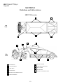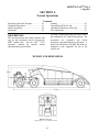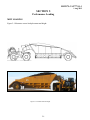
1
MHT175-CAT777-OPS-1
SPECIALTY HAULAGE SOLUTIONS FOR CONSTRUCTION AND MINING
OPERATORS MANUAL
MEGA CORP.®
700 Osuna Rd. N.E. • Albuquerque, NM 87113 • 1-800-345-8889 • 505-345-2661 • Fax 505-345-6190
www.megacorpinc.com
® MEGA Corp., Inc. All Rights Reserved
MHT175-CAT777(G)-1
1 Aug 2012
TABLE OF CONTENTS
Page
Section 1. Definitions and Abbreviations …………………………………………………...…. 1-1
Section 2. System Descriptions ………………………………………………………….….…
2-1
Section 3. Normal Operations ………………………………………………………………..... 3-1
Section 4. Limitations …………………..…….……………………………………………...… 4-1
Section 5. Performance Loading .………………………………………………………………. 5-1
Section 6. Appendix ………………………………………………………………………….... 6-1
A
MHT175-CAT777(G)-1
1 Aug 2012
TABLE OF CONTENTS
B(Blank)
MHT175-CAT777(G)-1
1 Aug 2012
SECTION 1
Definitions and Abbreviations
Contents
Description ………………………….….… 1-1
Warnings, Cautions & Notes ……………... 1-1
Shall, Will & May ……………................... 1-1
MHT175-CAT777(G) Overview ………… 1-2
Abbreviations ….……………………..… .. 1-3
DESCRIPTION
USE OF SHALL, WILL AND MAY
This technical manual contains information
required to safely operate the MHT175CAT777(G). See the CAT 777G Operations
and Safety manual for additional information
specific to the CAT 777G chassis.
Shall and Will – Used when application of a
procedure is mandatory.
Should – Used when application of a
procedure is recommended.
WARNINGS, CAUTIONS AND
NOTES
May - Used to indicate an acceptable or
suggested means of accomplishment.
The following definitions are found
throughout the manual and apply as follows:
Operating procedures and techniques, which
could result in personal injury and/or loss of
life if not carefully followed.
Operating procedures and techniques, which
could result in damage to equipment if not
carefully followed.
Operating procedures and techniques that are
considered essential to emphasis.
1-1
MHT175-CAT777(G)-1
1 Aug 2012
SECTION 1
Definitions and Abbreviations
MHT175 Overview
3
4
Top
View
3
7
4
9
10
1
8
11
Side
View
2
6
5
1
GOOSENECK
7
DECK & FENDER
2
LOWER HOPPER
8
TURN LIMIT INDICATOR
3
SIDE WALL
9
SPILL GUARD
REAR BOGIE
10
SIDE BOARDS
4
11
END-OF-LOAD INDICATORS
5
REAR AXLE & WHEEL GROUP
6
HITCH & SADDLE
1-2
MHT175-CAT777(G)-1
1 Aug 2012
SECTION 1
Definitions and Abbreviations
ABBREVIATIONS
ft - feet
gpm – gallons per minute
kg – kilograms
km/h – kilometers per hour
lbs – pounds
MHT – MEGA Coal Hauler
MHT – MEGA Hauler with Truck
mph – miles per hour
psi - pounds per square inch
1-3
MHT175-CAT777(G)-1
1 Aug 2012
SECTION 1
Definitions and Abbreviations
1-4(Blank)
MHT175-CAT777(G)-1
1 Aug 2012
SECTION 2
System Description
Contents
Coal Hauler Body (MHT) ………...….....
MHT Axle & Wheel Group …….............
Hitch Deck & Fender ……………….......
MHT Brake System …….........................
MHT Door System ………….………….. 2-6
MHT Lube System ……………………… 2-7
MHT Lighting System …………….......… 2-7
2-1
2-3
2-3
2-4
Lower Hopper Assembly
COAL HAULER BODY (MHT)
The MEGA 175 ton coal hauler is modular in
construction and comprised of four major sub
assemblies. The sub assemblies are the
gooseneck, lower hopper, side walls and the
rear bogie.
Gooseneck Assembly
The assembly is constructed of square steel
tubes, bolsters and plates. It provides for
mounting of door assemblies, hydraulic
actuators and lubrication blocks. The bolster
passage ways provide for the routing and
protection of hydraulic brake and door hosing
as well as electrical cabling.
Side Wall Assembly
The assembly is constructed of square steel
tubes, plates and channels. It contains an 18”
diameter hitch ball designed to be captured in
the tractor hitch socket allowing the trailer to
be towed. The compartment formed by the
gooseneck plating is used for mounting and
routing of all brake, door and electrical system
components. Components can be accessed
through the manhole covers mounted on the
upper deck.
The walls are constructed of steel tubes and
plates.
They provide for mounting of
clearance lights, side boards and load markers.
2-1
MHT175-CAT777(G)-1
1 Aug 2012
SECTION 2
System Description
Proper straight on contact between MHT and
pushing (boosting) machine is shown below:
Trailing Axle Frame Assembly
The trailing bogie is constructed of square
steel tubes and plates. The assembly provides
mounting for the rear axle assembly associated
brake system accumulators filters, manifolds,
and light. The rear of the bogie also contains a
push type bumper assembly.
Routine hard bumper contacts by the pushing
(boosting) machine will cause structural
fatigue and result in reduced trailer service
life.
The bumper may be configured as a pushblock or wrap-around style. The design
provides a pushing point to assist the MHT up
a grade in low traction conditions (wet, muddy
or icy haul road). The bumper assembly is
designed to be pushed straight on by the
pushing (boosting) machine.
Angled blade contact of the push-block style
bumper will reduce bull dozer blade to MHT
wheel clearance. Extreme blade angles will
cause blade/bit to wheel contact and damage
MHT tires. MHT and pushing (boosting)
machine operators must communicate to
maintain correct contact and maximum wheel
to blade/bit clearance.
Wrap-Around Style
Push-Block Style
2-2
MHT175-CAT777(G)-1
1 Aug 2012
SECTION 2
System Description
MHT AXLE & WHEEL GROUP
the MHT hitch ball and transfer loads to the
tractor. Mounting is also provided for deck
and fender assemblies.
Deck and Fenders
The MHT trailer axle and wheel group is the
same as the tractor drive axle assembly minus
drive gear. It is attached to the MHT trailing
axle frame by means of the same A-frame,
hard pan rod and struts. For more information
see the CAT operators/service manual and
brake system information contained in this
manual.
Constructed of square steel tubes, plates,
channels and grates that mounts to the hitch
and saddle assembly. The assembly contains
fenders, mud flaps, maintenance access doors,
walkway and a work platform.
Turn Limit Indicator
Mechanical
HITCH DECK AND FENDER
Turn Limit
Indicator
The hitch deck and fender is modular in design
and is comprised of three sub assemblies. The
assemblies are the hitch and saddles, deck and
fenders.
Hitch and Saddles
Gooseneck
Stop
Constructed of steel plate and mounted to the
tractor chassis rails and upper deck horse
collar. The turn limit indicator is designed to
contact the gooseneck stops and provide
visible indication of the maximum trailer
rotation left or right.
Constructed of steel plates and machined brass
bushings. The assembly is mounted to the
tractor chassis and pinned to the chassis pivot
bores. The machined brass bushings capture
2-3
MHT175-CAT777(G)-1
1 Aug 2012
SECTION 2
System Description
Electronic
The trailer brake activation is accomplished
with existing in-cab service brake pedal,
secondary brake control pedals as well as the
gear shift lever for parking brake.
Deceleration of the vehicle from running/
operating speed is typically accomplished by
using the retarder. Always consider road
conditions (wet, icy or slick) when
determining a means to decelerate or stop.
Retainer Mounted Roller
Switch
MHT Service Brakes
The tractor and MHT service brakes are
activated by pressing on the brake control
pedal. Pilot (signal) pressure from the tractor
proportions brake valves allowing accumulator
activation pressure to be routed to the slack
adjusters and apply the brakes.
In-Cab Mounted Warning
Box
Accumulators
The system consists of a roller switch mounted
on the hitch retaining plate and a warning box
located in the cab. The roller switch is
activated by flags mounted on the underside of
the ball skirt disc. When the trailer rotates
about 85° either side of center trail, the flag
will activate the switch in turn providing
power to activate the amber warning light and
audio horn on the warning box. The system
receives 24 VDC switched power from the
tractor.
The MHT is equipped with one additional
accumulators mounted on the trailing axle
frame that ensure brake activation pressure is
available in close proximity to the rear axle
brakes
MHT BRAKE SYSTEM
The MHT rear axle braking is integrated with
the existing CAT 777G tractor service,
secondary and parking brakes systems. MEGA
has added an additional scavenge pump one
additional accumulator (trailer mounted) a
modified brake valve and several restrictors
within the brake system to acquire a fully
functional cooling and activation system.
2-4
MHT175-CAT777(G)-1
1 Aug 2012
SECTION 2
System Description
Brake Valve & Slack Adjuster Groups
The MHT is configured with two different
brake valve and slack adjuster groups. One is
mounted in the trailer rear axle and the other is
on the tractor chassis on the rear frame.
Slack Adjusters
Parking Brake System
The tractor and MHT parking brake are
activated by moving the gear selector lever to
the park position P. This action opens the
brake retract circuit allowing the spring
activated parking brake to be applied.
Brake Cooling System
The MHT axles receive brake cooling oil from
the tractor torque converter through the oil
cooler circuit. Oil is returned to the tractor
cooling circuit through the added scavenge
pump.
Tractor Brake Valve
The trailer brake valve will route activation
pressure to the trailer slack adjuster to apply
trailer brakes. The activation should occur first
in the sequencing of the three axles (trailer,
tractor drive and tractor steering). This built in
delay ensures the trailer stays in trail during
initial brake applications.
Scavenge Pump
Added
Scavenge Pump
The tractor drive axle brake valve will route
activation pressure to the chassis drive axle
slack adjusters to apply drive axle brakes. This
activation will be slowed down by restrictors
in the drive axle brake valve circuit. This
delay will allow drive axle activation to occur
second in the braking sequence.
Brake Pump
Hoist/Brake
Cooling Pump
An additional scavenge pump was added to
assist in pulling MHT brake cooling oil back
into the tractor cooling circuit. This scavenge
pump is mounted between the tractor brake
cooling pump and the brake pump. Several
restrictors were added on the steering tire
cooling circuit to allow proper oil return flow
from the trailer. Otherwise the tractor drive
axle cooling circuit is unchanged and operates
per the CAT service/operators manual.
Finally, the steering tire slack adjuster will
receive activation pressure at a further reduced
rate because of smaller restrictors feeding the
steering wheel slack adjuster. This delay will
ensure steering wheel activation occurs last in
the braking sequence.
Secondary Brake System
The tractor and MHT secondary braking are
activated by pressing on the secondary brake
control pedal. This action opens the brake
retract circuit allowing the spring activated
2-5
MHT175-CAT777(G)-1
1 Aug 2012
SECTION 2
System Description
Hoist Control Lever
MHT DOOR SYSTEM
The system is comprised of two hinged doors,
activation cylinders, hosing and a proximity
switch (optional).
The hydraulic door
cylinders are powered hydraulics from the
tractor hoist valve and controlled by the in-cab
hoist control lever to open and close the doors.
Hoist Control
Lever
LOWER
RAISE
FLOAT
HOLD
Mounted in the cab and used to open and close
the MHT doors. The lever is labeled for dump
body operations and performs the four
functions of RAISE, HOLD, FLOAT and
LOWER. See the CAT 777(G) operators
manual for more system information.
Hydraulics
The MHT uses the in-cab hoist control lever
functions as follows:
RAISE - Open MHT doors.
HOLD - Hold MHT doors in fixed position
for transiting haul roads with or
without a load.
FLOAT – Disable by ECM software for
trailer MHT applications.
LOWER - Close MHT doors.
Doors are opened and closed by hydraulic
cylinders that are mounted on the doors ends
(standard) or center (optional).
These
cylinders use hydraulic pressure routed from
the tractor hoist valve to open and close the
doors. The RAISE side of the hoist valve is
used to open the doors while the LOWER side
of the hoist valve is used to close the doors.
Control of the doors is commanded by use of
the in-cab hoist control lever.
Door Indicator
A door indicator switch is normally installed
on the MHT lower hopper assembly. The door
switch is intended to contact the inner door
swing arm when the dump doors are in the
closed position and extinguish the dump body
warning light. When the doors are open the
switch will illuminate the dump body warning
light. Under warning light conditions the
ECM will only allow preprogrammed low gear
operations.
.
2-6
MHT175-CAT777(G)-1
1 Aug 2012
SECTION 2
System Description
Intermediate Door Position Indicator (If
Equipped)
A system that contains a cab mounted
indicator box and an additional door position
proximity switch. The indicator switch is
normally installed on the MHT LH lower
hopper assembly. The door switch is intended
to contact the inner door swing arm when the
dump doors are in a customer determined
intermediate position. When doors are open to
a customer determined position, the cab
control box will illuminate a green light and
provide an audio tone.
This system is designed to assist operators in
reduce/control
windrow
heights
when
performing stockpile operations.
MHT LUBE SYSTEM
The MHT is lubricated through central
lubrication blocks that may be connected to
the tractor auto lube system if installed.
Lubrication blocks service MHT axle A-frame,
hardpan rod, axle struts, hydraulic cylinder
pins and hitch ball socket assembly
MHT LIGHTING SYSTEM
The system contains brake, turn signal,
backing, clearance and work lights. Some
optional lighting features may include load,
backing and auxiliary equipment lighting. All
lighting is controlled by existing switches
mounted in the cab or modified by dealers to
operate at a junction box or added in-cab
control box.
2-7
MHT175-CAT777(G)-1
1 Aug 2012
SECTION 2
System Description
2-8(Blank)
MHT175-CAT777(G)-1
1 Aug 2012
SECTION 3
Limitations
Contents
Maximum Allowable Weights ………..… 3-1
MHT Gooseneck …………………..…… 3-1
MAXIMUM ALLOWABLE
WEIGHTS
2. OSCILLATION
The hitch ball is limited to 12° as shown
below.
1. Maximum allowable gross machine weight
is 627,202 lbs/284,494 kg
12
°
2. Maximum allowable load for the MHT is:
a. 175 tons
b. 350,000lbs
c. 158,758kg
Operating the MHT above maximum load
will decrease MHT structure and
component service life.
Hitch ball oscillations greater than 12° will
result in hitch ball contact with hitch socket
upper retaining plate. Repeated contact may
cause failure of upper hitch socket retaining
plate bolts and reduce service life of the hitch
ball assembly.
MHT GOOSENECK
1. ARTICULATION
The gooseneck is limited to 90°
articulation right and left of centerline trail
as shown below.
MHT Top View
Gooseneck articulation beyond 90° will result
in turn limit indicator to gooseneck stop
contact. Repeated contact may cause damage
to stops and indicators.
3-1
MHT175-CAT777(G)-1
1 Aug 2012
SECTION 3
Limitations
3-2(Blank)
MHT175-CAT777(G)-1
1 Aug 2012
SECTION 4
Normal Operations
Contents
Maximum Allowable Weights…………
Weight & Dimensions ……………..…..
Before Operations ………….………..…
Operations ……….…………………..…
Loading …………………………………
Transitioning With A Load …………....
Unloading (Stationary or Moving)..……
After Operations ……………….………
4-1
4-1
4-2
4-2
4-2
4-3
4-3
4-3
The MHT normal operating procedures mirror
the established CAT format of operations. The
procedures are separated into before
operations, operations and after operations. A
pocket size checklist of all MHT procedures is
contained in the Appendix for use in the
vehicle cab.
DESCRIPTION
This section provides the vehicle operator with
step by step procedures used to operate the
MHT system only. See the CAT 777(G)
operators’ manual for specific tractor
operations and system details.
WEIGHT AND DIMENSIONS
MHT175-CAT777(G)
Empty Weight = 231,517 LBS/105,015 KG
4-1
MHT175-CAT777(G)-1
1 Aug 2012
SECTION 4
Normal Operations
13. LH Door Hydraulic Cylinders, Structure
Cavity Drain Holes and Lights –
CHECKED FOR DAMAGE, SECURITY
AND LEAKS
BEFORE OPERATIONS
These procedures are used to perform a walkaround inspection of the MHT system before
use or beginning of the shift. This inspection
is in addition to and does not replace the CAT
777(G) inspection requirements.
14. Trailer Axle Frame Assembly, Axle
Assembly, Manifolds and Accumulators –
CHECK FOR DAMAGE, SECURITY
AND LEAKS
1. Vehicle Engine – AS REQUIRED
2. Chocks – INSTALLED AS REQUIRED
15. Tail Light Assemblies – CHECKED FOR
DAMAGE
3. Transmission Control Lever – P (Park)
4. Hoist Control Lever – HOLD
16. RH Door Hydraulic Cylinders, Structure
Cavity Drain Holes and Lights –
CHECKED FOR DAMAGE, SECURITY
AND LEAKS
5. Hitch Ball Retaining Plate –– CHECKED
FOR DAMAGE AND SECURITY (Lift
ball skirt and check for loose or sheared
bolt heads.)
17. RH Hitch Deck and Fender – CHECKED
FOR DAMAGE AND SECURED
6. Turn Limit Indicator – CHECKED FOR
SECURITY AND DAMAGE
18. (If Equipped) RH Consolidated Service
Center – LEVELS CHECKED.
7. Upper Deck Assembly – CHECKED FOR
DAMAGE AND SECURITY
OPERATIONS
Use these procedures to safely operate the
standard and optional systems installed on the
MHT175-CAT777(G).
8. Upper Hitch and Hydraulic Hosing –
CHECKED FOR DAMAGE, SECURITY
AND LEAKS
LOADING
1. Hoist Control Lever – LOWER (Doors
fully closed) then immediately to HOLD
9. Upper Gooseneck and Hosing –
CHECKED FOR DAMAGE, SECURITY
AND LEAKS
10. Chassis Hydraulic Tank – SERVICED
If doors do not fully close and the body
position light is on, cycle the hoist control
lever to LOWER (doors closed) then
immediately back to HOLD. Ensure the
body position warning light is off.
11. LH Hitch Deck and Fender – CHECKED
AND SECURED
12. Gooseneck, Access Panels and Mud Flaps
– CHECKED AND SECURED
2. Hoist Control Lever – HOLD
3. Body Position Warning Light – OFF
4-2
MHT175-CAT777(G)-1
1 Aug 2012
SECTION 4
Normal Operations
4. Positioned MHT for loading within the
load markers.
UNLOADING (Moving)
5. Transmission Control Lever – P (Park
It is highly recommended a dozer be available
to keep dump entry and exit paths level during
stockpile operations.
6. On-Load – As Required
Once on-load is complete
1. When entering stockpile to dump, find a
level area that will not require any turning
once the dump has started.
7. Transmission Control Lever – As Required
8. Move away from the loading area.
2. The truck should be locked in first or
second gear.
TRANSITING WITH A LOAD
1. While driving periodically scan side view
mirrors for evidence of doors opening.
3. Determine a safe ground speed for the
dump pass based on environmental/road
conditions, stockpile route, and appropriate
material flow to prevent trailer axle high
centering or hitch over oscillation;.
2. Body Position Warning Light – OFF
UNLOADING (Stationary)
1. Position MHT for unloading.
4. After the unit has entered the stockpile and
is locked in the correct gear and is in a
straight line with the desired ground speed
established, the dump doors can be opened
to an intermediate position.
2. Brakes – As Required
3. Hoist Control Lever – AS DESIRED TO
DUMP LOAD
5. When opening the dump doors they should
not be opened up all the way to keep
material from flowing underneath the
trailer tires. The doors should be opened
slowly by bumping the dump lever.
(Three to four bumps on the dump lever is
all that is required). Use intermediate door
position system if equipped
Once load is dumped
4. Hoist Control Lever – LOWER (Doors
fully closed) then immediately to HOLD
If doors do not fully close and the body
position light is on, cycle the hoist control
lever to LOWER (doors closed) then
immediately back to HOLD. Ensure the
body position warning light is off.
6. The operator should string out the load so
that the trailer doesn’t ride up on the coal
that is being dumped.
5. Hoist Control Lever – HOLD
4-3
MHT175-CAT777(G)-1
1 Aug 2012
SECTION 3
Normal Operations
5. Hitch Ball Retaining Plate –– CHECKED
FOR DAMAGE AND SECURITY (Lift
ball skirt and check for loose or sheared
bolt heads.)
Hitch ball oscillations greater than 12° will
result in hitch ball contact with hitch socket
upper retaining plate. Repeated contact may
cause failure of upper hitch socket retaining
plate bolts and reduce service life of the hitch
ball assembly.
6. Turn Limit Indicator – CHECKED FOR
SECURITY AND DAMAGE
7. Upper Deck Assembly – CHECKED FOR
DAMAGE AND SECURITY
7. Once the trailer has been dumped the
operator can then allow the truck to shift as
necessary while he/she is closing the
doors.
8. Upper Hitch and Hydraulic Hosing –
CHECKED FOR DAMAGE, SECURITY
AND LEAKS
8. Once the doors have reached the closed
position the operator must then return the
dump lever to the hold position with no
hesitation in the float setting.
9. Upper Gooseneck and Hosing –
CHECKED FOR DAMAGE, SECURITY
AND LEAKS
9. If there is any hesitation passing through
the float position, the operator must reopen
the doors slightly and close them again
without hesitation.
10. Chassis Hydraulic Tank – SERVICED
10. Continue Safely back to the pit driving
appropriate to the road conditions.
12. Gooseneck, Access Panels and Mud Flaps
CHECKED AND SECURED
AFTER OPERATIONS
13. LH Door Hydraulic Cylinders, Structure
Cavity Drain Holes and Lights –
CHECKED FOR DAMAGE, SECURITY
AND LEAKS
11. LH Hitch Deck and Fender – CHECKED
AND SECURED
These procedures are used to perform a walkaround inspection after using the MHT175CAT777(G) system. This inspection is in
addition to and does not replace the CAT
777(G) inspection requirements.
14. Trailer Axle Frame Assembly, Axle
Assembly, Manifolds and Accumulators –
CHECK FOR DAMAGE, SECURITY
AND LEAKS
1. Vehicle Engine – AS REQUIRED
2. Chocks – INSTALLED AS REQUIRED
15. Tail Light Assemblies – CHECKED FOR
DAMAGE
3. Transmission Control Lever – P (Park)
4. Hoist Control Lever – HOLD
4-4
MHT175-CAT777(G)-1
1 Aug 2012
SECTION 4
Normal Operations
16. RH Door Hydraulic Cylinders, Structure
Cavity Drain Holes and Lights –
CHECKED FOR DAMAGE, SECURITY
AND LEAKS
6. Confirm with maintenance and perform
actual inspection of the chassis systems to
ensure the following brake and control
system configuration exist.
17. RH Hitch Deck and Fender – CHECKED
FOR DAMAGE AND SECURED
Brake Cooling Manifold (RT Side)
18. (If Equipped) RH Consolidated Service
Center – LEVELS CHECKED.
a. A jumper hose connects the brake
cooling port to the brake return port
(-32 fitting).
DECOUPLED OPERATIONS
Brake Activation Manifold (LT Side)
The procedures are used to operate the chassis
with the trailer removed (decoupled).
Decoupled operations can only be attempted
when the brake and associated control
systems are reconfigured for decoupled
operations.
b. Grease port trailer supply port is
capped off (-8 fitting).
c. Brake accumulator trailer supply port
is capped off (-16 fitting).
d. Trailer service return port is capped
off (-16 fitting).
Do not operate the chassis (decoupled) from
the trailer unless the brake and associated
control systems are configured properly.
Failure to ensure proper brake system
configuration exists, may result in inoperative
service, parking and secondary brake systems.
Operating the chassis with inoperative brake
systems may result in personal injury or
death.
e. Trailer E-Brake/Parking brake retract
supply port is capped off (-10 fitting).
f. Trailer service brake signal in and out
ports (-8 fittings).
Control System
INSPECTION
g. Chassis mounted junction box or Yharness connection is configured or
jumpered to allow normal tail light
and backup alarm functions.
1. Vehicle Engine – AS REQUIERED
2. Chocks – INSTALLED
3. Transmission Control Lever –P (Park)
7. Ensure hitch and deck area are clear of
tools and debris.
4. Hoist Control Lever – HOLD
8. Vehicle Engine - Start
5. Gain access to forward hitch area by using
the deck assembly. Identify the LT and
RT junction manifolds.
4-5
MHT175-CAT777(G)-1
1 Aug 2012
SECTION 3
Normal Operations
9. While machine is running and parking
brake function is assured, check
reconfigured manifolds for leaks.
10. Check brake lights, turn signals and
back up alarm are functioning properly.
11. Chocks – REMOVED
OPERATION
12. Front Brake Activation Switch – ON
13. Ensure parking brake is functioning.
Ensure parking brake advisory light
illuminates when gear selector is in park
(P).
Do not operate the machine if the parking
brake system is malfunctioning or
inoperative.
14. Gear Selector Lever – “D” Drive.
15. At 3-5 MPH activate the service brake
to ensure proper function.
Do not operate the machine if the service
brake system is malfunctioning or
inoperative.
16. Once all brake and control systems are
operating properly, move the machine as
required.
17. Continue to monitor brake cooling
temperatures to ensure brakes are not
dragging or a malfunction exists in the
cooling circuit.
4-6
MHT175-CAT777(G)-1
1 Aug 2012
SECTION 5
Performance Loading
MHT LOADING
Figure 5-1 illustrates correct load placement and height.
Figure 5-1 Load Placement & Height
5-1
MHT175-CAT777(G)-1
1 Aug 2012
SECTION 5
Performance Loading
5-2(Blank)
MHT175-CAT777(G)-1
1 Aug 2012
SECTION 6
Appendix
MHT175-CAT777(G)CL-1
1 Aug 2012
MHT175
OPERATORS
CHECKLIST
6-1
MHT175-CAT777(G)-1
1 Aug 2012
SECTION 6
Appendix
MHT175-CAT777(G)CL-1
1 Aug 2012
TABLE OF CONTENTS
Title
Page
1. BEFORE OPERATIONS……..…….. N-2
2. OPERATIONS
A. Loading (Stationary or Moving) N-4
B. Transiting with a Load ….…… N-5
C. Unloading …………………… N-6
3.
AFTER OPERATIONS…………… N-7
4. DECOUPLED OPERATIONS…… ..N-9
N-1
6-2
MHT175-CAT777(G)-1
1 Aug 2012
SECTION 6
Appendix
MHT175-CAT777(G)CL-1
1 Aug 2012
BEFORE OPERATIONS
These procedures are used to perform a walk-around
inspection of the MHT175-CAT777(G) system before
use or beginning of the shift. This inspection is in
addition to and does not replace the CAT 777(G)
inspection requirements. These procedures are used to
perform a walk-around inspection of the MHT system
before use or beginning of the shift. This inspection is
in addition to and does not replace the CAT 777(G)
inspection requirements.
1. Vehicle Engine – AS REQUIRED
2. Chocks – INSTALLED
3. Transmission Control Lever – P (Park)
4. Hoist Control Lever – HOLD
5. Hitch Ball Retaining Plate – CHECKED FOR
DAMAGE AND SECURITY (Lift ball skirt and
check for loose or sheared bolt heads.)
6. Turn Limit Indicator – CHECKED FOR
SECURITY AND DAMAGE
N-2
6-3
MHT175-CAT777(G)-1
1 Aug 2012
SECTION 6
Appendix
MHT175-CAT777(G)CL-1
1 Aug 2012
7. Upper Deck Assembly – CHECKED FOR
DAMAGE AND SECURITY
8. Upper Hitch and Hydraulic Hosing – CHECKED
FOR DAMAGE, SECURITY AND LEAKS
9. Upper Gooseneck and Hosing – CHECKED FOR
DAMAGE, SECURITY AND LEAKS
10. Chassis Hydraulic Tank - SERVICED
11. LH Hitch Deck and Fender – CHECKED AND
SECURED
12. Gooseneck, Access Panels and Mud Flaps –
CHECKED AND SECURED
13. LH Door Hydraulic Cylinders, Structure Cavity
Drain Holes and Lights – CHECKED FOR
DAMAGE, SECURITY AND LEAKS
14. Trailer Axle Frame Assembly, Axle Assembly,
manifolds and Accumulators - CHECK FOR
DAMAGE, SECURITY AND LEAKS.
N-3
6-4
MHT175-CAT777(G)-1
1 Aug 2012
SECTION 6
Appendix
MHT175-CAT777(G)CL-1
1 Aug 2012
15. Tail Lights Assemblies – CHECKED FOR
DAMAGE
16. RH Door Hydraulic Cylinders, Structure Cavity
Drain Holes and Lights – CHECKED FOR
DAMAGE, SECURITY AND LEAKS
17. RH Hitch Deck and Fender – CHECKED FOR
DAMAGE AND SECURED
18. (If Equipped) RH Consolidated Service Center –
Levels Checked.
OPERATIONS
Use these procedures to safely operate the standard and
optional systems installed on the MHT175CAT777(G).
N-4
6-5
MHT175-CAT777(G)-1
1 Aug 2012
SECTION 6
Appendix
MHT175-CAT777(G)CL-1
1 Aug 2012
LOADING
1. Hoist Control Lever – LOWER (Doors fully
closed) then immediately to HOLD
If doors do not fully close and the body position
light is on, cycle the hoist control lever to LOWER
(doors closed) then immediately back to HOLD.
Ensure the body position warning light is off.
2. Hoist Control Lever – HOLD
3. Body Position Warning Light – OFF
4. Positioned MHT for loading within the load
markers.
5. Transmission Control Lever – P (Park)
6. On-Load – As Required
Once on-load is complete
7. Transmission Control Lever – As Required
8. Move away from the loading area.
N-5
6-6
MHT175-CAT777(G)-1
1 Aug 2012
SECTION 6
Appendix
MHT175-CAT777(G)CL-1
1 Aug 2012
TRANSITING WITH A LOAD
1. While driving periodically scan side view mirrors
for evidence of doors opening.
2. Body Position Warning Light – OFF
UNLOADING (Stationary)
1. Position MHT for unloading.
2. Brakes – As Required
3. Hoist Control Lever – AS DESIRED TO DUMP
LOAD
Once load is dumped
4. Hoist Control Lever – LOWER (Doors fully
closed) then immediately to HOLD
If doors do not fully close and the body position
light is on, cycle the hoist control lever to LOWER
(doors closed) then immediately back to HOLD.
Ensure the body position warning light is off.
N-6
6-7
MHT175-CAT777(G)-1
1 Aug 2012
SECTION 6
Appendix
MHT175-CAT777(G)CL-1
1 Aug 2012
5. Hoist Control Lever – HOLD
UNLOADING (Moving)
It is highly recommended a dozer be available to keep
dump entry and exit paths level during stockpile
operations.
1. When entering stockpile to dump, find a level area
that will not require any turning once the dump has
started.
2. The truck should be locked in first or second gear.
3. Determine a safe ground speed for the dump pass
based on environmental/road conditions, stockpile
route, and appropriate material flow to prevent
trailer axle high centering or hitch over oscillation.
4. After the unit has entered the stockpile and is
locked in the correct gear and is in a straight line
with the desired ground speed established, the
dump doors can be opened to an intermediate
position.
N-7
6-8
MHT175-CAT777(G)-1
1 Aug 2012
SECTION 6
Appendix
MHT175-CAT777(G)CL-1
1 Aug 2012
5. When opening the dump doors they should not be
opened up all the way to keep material from
flowing underneath the trailer tires. The doors
should be opened slowly by bumping the dump
lever. (Three to four bumps on the dump lever is
all that is required). Use intermediate door position
system if equipped.
6. The operator should string out the load so that the
trailer doesn’t ride up on the coal that is being
dumped.
Hitch ball oscillations greater than 12° will result
in hitch ball contact with hitch socket upper
retaining plate. Repeated contact may cause failure
of upper hitch socket retaining plate bolts and
reduce service life of the hitch ball assembly.
7. Once the trailer has been dumped the operator can
then allow the truck to shift as necessary while
he/she is closing the doors.
8. Once the doors have reached the closed position
the operator must then return the dump lever to the
hold position with no hesitation in the float setting.
N-8
6-9
MHT175-CAT777(G)-1
1 Aug 2012
SECTION 6
Appendix
MHT175-CAT777(G)CL-1
1 Aug 2012
9. If there is any hesitation passing through the float
position, the operator must reopen the doors
slightly and close them again without hesitation.
10. Continue safely back to the pit driving appropriate
to the road conditions.
AFTER OPERATIONS
These procedures are used to perform a walk-around
inspection after using the MHT175-CAT777(G)
system. This inspection is in addition to and does not
replace the CAT 777(G) inspection requirements.
1. Transmission Control Lever – P (Park)
2. Vehicle Engine – AS REQUIRED
3. Hoist Control Lever – HOLD
4. Turn Limit Indicator – CHECKED
DAMAGE AND SECURITY
FOR
5. Upper Deck Assembly – CHECKED FOR
DAMAGE AND SECURITY
N-9
6-10
MHT175-CAT777(G)-1
1 Aug 2012
SECTION 6
Appendix
MHT175-CAT777(G)CL-1
1 Aug 2012
6. Upper Hitch and Hydraulic Hosing – CHECKED
FOR DAMAGE, SECURITY AND LEAKS
7. Upper Gooseneck and Hosing – CHECKED FOR
DAMAGE, SECURITY AND LEAKS
8. Chocks – INSTALLED
9. Vehicle Hydraulic Tank – SERVICED
10. LH Hitch Deck and Fender – CHECKED FOR
DAMAGE AND SECURED
11. Gooseneck, Access Panels and Mud Flaps –
CHECKED AND SECURED
12. LH Door Hydraulic Cylinders, Structure Cavity
Drain Holes and Lights – CHECKED FOR
DAMAGE, SECURITY AND LEAKS
13. Rear Bogie, Axle Assembly, Filters and
Accumulators – CHECK FOR DAMAGE LEAKS
AND SECURITY
N-10
6-11
MHT175-CAT777(G)-1
1 Aug 2012
SECTION 6
Appendix
MHT175-CAT777(G)CL-1
1 Aug 2012
14. Tail Light
DAMAGE
Assemblies
–
CHECKED
FOR
15. RH Hitch Deck and Fender – CHECKED AND
SECURED
DECOUPLED OPERATIONS
The procedures are used to operate the chassis with the
trailer removed (decoupled). Decoupled operations can
only be attempted when the brake and associated
control systems are reconfigured for decoupled
operations.
Do not operate the chassis (decoupled) from the trailer
unless the brake and associated control systems are
configured properly. Failure to ensure proper brake
system reconfiguration exists may result in inoperative
service, parking and secondary brake systems,
operating the chassis with inoperative brake systems
mat result in personal injury or death.
N-11
6-12
MHT175-CAT777(G)-1
1 Aug 2012
SECTION 6
Appendix
MHT175-CAT777(G)CL-1
1 Aug 2012
INSPECTION
1. Vehicle Engine – AS REQUIRED
2. Chocks – INSTALLED
3. Transmission Control Lever – P (Park)
4. Hoist Control Lever – HOLD
5. Gain access to forward hitch area by using the deck
assembly. Identify the LT and RT junction
manifolds.
6. Confirm with Maintenance and perform actual
inspection of the chassis systems to ensure the
following brake and control system configuration
Brake Cooling Manifold (RT side)
A. A jumper hose connect the brake cooling port
to the brake return port (-32 fitting).
N-12
6-13
MHT175-CAT777(G)-1
1 Aug 2012
SECTION 6
Appendix
MHT175-CAT777(G)CL-1
1 Aug 2012
Brake Activation Manifold (LT)
B. Grease port trailer supply port is capped of f
( - 8 fitting).
C. Brake accumulator trailer supply port is capped
off (-16 fitting)
D. Trailer service return port is capped off (-16
fitting)
E. Trailer E-Brake/Parking brake retract supply
port is capped off (-10 fitting).
F. Trailer service brake signal in and out ports (-8
fittings)
Control System
G. Chassis mounted junction box or Y – harness
connection is configured or jumpered to allow
normal tail light and backup alarm functions.
7. Ensure hitch and deck area are clear of tools and
debris.
N-13
6-14
MHT175-CAT777(G)-1
1 Aug 2012
SECTION 6
Appendix
MHT175-CAT777(G)CL-1
1 Aug 2012
8. Vehicle Engine – Start
9. While machine is running and parking brake
function is assured, check reconfigured manifolds
for leaks.
10. Check brake lights, turn signals and back up alarm
are functioning properly.
11. Chocks - REMOVED
OPERATION
12. Front Brake Activation Switch – ON
13. Ensure parking brake is functioning. Ensure
parking brake advisory light illuminates when gear
selector is in park (P).
Do not operate the machine if the parking brake
system is malfunctioning or inoperative.
14. Gear Selector Lever – “D” Drive
N-14
6-15
MHT175-CAT777(G)-1
1 Aug 2012
SECTION 6
Appendix
MHT175-CAT777(G)CL-1
1 Aug 2012
15. At 3-5 MPH activate the service brake to ensure
proper function.
Do not operate the machine if the service brake
system is malfunctioning or inoperative.
16. Once all brake and control systems are operating
properly, move the machine as required.
17. Continue to monitor brake cooling temperatures to
ensure brakes are not dragging or a malfunction
exists in the cooling circuit.
N-15
6-16