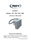
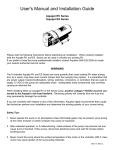
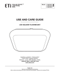
1
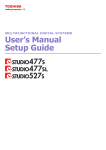
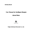
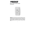
Heritage MedCall
Sentry E-Call
Model HM-527
Resident Host Panel
430-527B 0305
©Heritage MedCall, Inc.
Issue 1, March 2005
Heritage Medcall Sentry Emergency Call System
Model 527 Host Panel
Installation and Service Instructions
DESCRIPTION
The Sentry Host Panel Model HM-527 is the master
communication panel for each individual apartment.
The host panel may be the only device in the apartment or it may be installed to support peripheral
devices such as smoke detectors and remote call
stations. The host panel is wired via a pre-wired Model
HM-582 connector. The host panel is equipped with a
pull cord for placing emergency calls, a check-in
button for feature operation and LED's to signal
operation. From the host panel's inception there have
been a number of revisions to update the design
which altered the host panel's connections and
operation. In general, revisions A through C are
identified by the connector placement on the upper
left corner of the circuit board, revision D and E are
identified by the connector placement near the center
of the board, and the current version, revision F, has
the connector placed in the lower right corner of the
circuit board and is also clearly identified by markings
on the circuit board (see Figure 2).
Data LED
Green
Verify LED
Red
Check In
LED - Red
Check In
Button
FIGURE 1 LAYOUT
INSTALLATION
LAYOUT
Each individual apartment is equipped with one host
panel, usually installed in the master bathroom for the
convenience of using the daily Assurance Check-In
feature. The host panel can monitor up to five remote
call stations that are usually located in other rooms of
the apartment. The host panel also controls and
monitors up to 5 smoke detectors. Most building
codes require a minimum of one smoke detector per
bedroom.
There are three light emitting diodes (LEDs) visible on
the front of the host panel, refer to Figure 1. The left
red LED is the CHECK-IN LED. This LED, 1) lights to
verify the CHECK-IN button key press, 2) flashes
during the assurance period until the CHECK-IN
button is pressed and 3) flashes with the VERIFY
LED when the panel does an internal reset when no
data is present. The right red LED is the VERIFY
LED. This LED 1) flashes while an emergency call is
placed by the pull cord, 2) lights steady when a call
has been acknowledged by the console and 3)
flashes with the CHECK-IN LED when the panel does
an internal reset when no data is present. The center
green LED is the DATA LED. This LED flashes each
time the host panel transmits data to the console.
During normal operation this LED flashes once every
three to five seconds. When a call is placed or
cancelled it will flash rapidly three times indicating
data communication with the console.
Apartment device options include: remote check-in
stations, wireless pendant receivers and transmitters,
dome lights, strobe lights, automatic check-in devices
and security keypads. See OPTIONS section for
details.
The Sentry system’s wiring is usually organized into
groups of 30 to 50 apartments on a data line. A cable
is looped from a terminal block to the host panels in
adjacent apartments. The data line and power are
usually supplied in a single, 2 pair cable. The data
lines can easily support the 51 host panel limit,
however voltage drops force a limit to the distance
that DC can be supplied. When using the recommended West Penn #374 cable, never exceed more
than 6-8 apartments on one cable. The Sentry HM588 terminal block provides a simple means for
organizing the wiring to apartment groups. Refer to
the Sentry Wiring Design Guide (390-108) for additional information.
The CHECK-IN button is used to 1) cancel emergency
calls, 2) check in during the assurance period (if
programmed in the console), and 3) to reset the
smoke detectors after smoke has cleared when using
HM-560B smoke detectors (previous HM-560 smoke
detectors self-reset).
Page 1
430-527B 0305 ©Heritage MedCall, Inc.
Issue 1, March 2005
Heritage Medcall Sentry Emergency Call System
Model 527 Host Panel
Installation and Service Instructions
HM-527A - E
FRONT PANEL
HM-527A
REAR CONNECTOR LOCATED
UPPER LEFT CORNER
HM-527B
REAR CONNECTOR LOCATED
UPPER LEFT CORNER
HM-527C
REAR CONNECTOR LOCATED
UPPER LEFT CORNER
HM-527D
REAR CONNECTOR
LOCATED IN CENTER
HM-527E
REAR CONNECTOR
LOCATED IN CENTER
HM-527F
REAR CONNECTOR LOCATED
BOTTOM RIGHT
HM-527F
FRONT PANEL NOTE: HERITAGE
MEDCALL ON LABEL
FIGURE 2 HOST PANEL IDENTIFICATION
Page 2
430-527B 0305 ©Heritage MedCall, Inc.
Issue 1, March 2005
Heritage Medcall Sentry Emergency Call System
Model 527 Host Panel
Installation and Service Instructions
APARTMENT WIRING
MOUNTING
The call stations and smoke detectors are wired as
shown in the attached wiring diagrams. Refer to the
Smoke Detector Installation Manual (430-560 or 430560B) and Wireless Pendant Installation Manual (430548) for additional details on their installation and
service. Device wiring and the looped power and data
lines are attached to the HM-582 Host Panel Connector at the two-gang electrical box where the host
panel will be mounted.
The Host Panel is mounted on the wall, to an electrical box with a two gang plaster ring. Mount to the
box with the four screws provided. DO NOT OVER
TIGHTEN SCREWS as they will distort the panel.
Make sure plaster, wallpaper, or other material does
not interfere with the pull cord and switch lever. Test
the pull cord to confirm proper switch operation.
Use wirenuts or crimp type connectors and apply tape
or dress unused wires so they cannot touch each
other, the circuit board or the electrical box.
A preliminary test of the host panel can be performed
by applying DC power without console operation
(data). When powered, the panel will flash it’s two red
LED’s every 20 seconds to indicate power is applied
and the panel is functioning. Connected devices will
have power. Remote emergency switches, and
wireless pendants operation can be tested by their
operation and the function of the verify LED and
smoke detectors can be tested and their operation
verified. Model HM-560 Smoke Detectors can be
tested by pressing the test button and listening for the
alarm, (hold the test button for at least 10 seconds)
and for HM-560B Smoke Detectors, they can be
tested with smoke and/or a magnet. Refer to the
Smoke Detector Installation and Service Manual for
details.
HOST PANEL TESTING
DIP SWITCH SETTINGS
All host panels are set to an individual address code
via the 6 position dipswitch on revisions A through E
and via the 8 position address/option switch of the
current revision F models. Begin with the address “0”
at the first apartment on the data line and advance to
the next address for the panel in the next apartment.
Continue with all the apartments that will be wired to
the same data line. Host panels use addresses 0 to
51, but not all addresses have to be used. Host
panels are not required to be set in any numerical
order. Attempts to match apartment numbers, floor
numbers or other codes often do not work and cause
programming problems later. Make sure to record the
selected address with the apartment number on
copies of the Sentry Programming Sheet #410-524D
included in this manual. When the installation is
complete, use the program sheet(s) for programming
of the system software. On the current revision F
host panel there are two additional option switches.
Switch 7 is used to set the host panel for the type of
smoke detector to which it is connected. OFF
(down)(default) is for the HM-560 smoke detector
(manufactured by System Sensor® with their P/N
2012B or 2012H) and ON (up) is for the HM-560B
smoke detector (manufactured by ESL® with their P/
N 449CST). Switch 8 selects if the Auxiliary Input is
terminated by an internal EOL resistor. Switch 8
(ON)(default) connects an internal EOL resistor
across the Aux. Input when it is not used for optional
Wireless Pendants. If the Aux. Input is to be used
the switch should be set to OFF (down) and an EOL
resistor used at the connected device for wiring
supervision.
When the console is operating, the panels are tested
by the controller. The host panel will flash the center
green indicator to show the panel is operating properly. The console screen will list panels that do not
communicate properly.
OPTIONS
REMOTE PULL CORDS - Model HM-541 single-gang
remote pull stations can be mounted in different
rooms of the apartment to allow closer access to
emergency pull cords. These devices include a verify
LED to signal call placement.
WIRELESS PENDANT - Wireless remote pendant
buttons are used as a portable means to summon
help. This option requires the installation of the HM547 Pendant Receiver. The receiver is usually installed at the location of the smoke detector.
DOME LIGHT - Apartments can be equipped with
hallway dome lights to guide an attendant during an
emergency event. The dome light operation follows
the function of the verify LED.
Page 3
430-527B 0305 ©Heritage MedCall, Inc.
Issue 1, March 2005
Heritage Medcall Sentry Emergency Call System
Model 527 Host Panel
Installation and Service Instructions
STROBE LIGHT - A strobe light can be installed in an
apartment for the hearing impaired or can be mounted
outdoors of a villa to guide emergency personnel. The
dome light operation follows the function of the verify
LED.
REMOTE CHECK-IN STATION - The host panel can
be special ordered with a connector to allow for
remote check-in. Remote check-in stations are used
in apartments where it may be desired to operate the
daily check-in function at more than one location. The
two-gang remote check-in panel (#HM-544) also
includes an emergency pull cord. Six conductor
cable is required between the host and remote checkin stations.
AUTOMATIC CHECK-IN - A motion detector device
can be installed as a remote check-in station for
automatic check-in. When a person’s movement is
detected during the check-in time, the system will
automatically log them in.
SECURITY SYSTEM - Host Panels version D or later
can interface with the Sentry HM-694 Security
keypad. This option connects to alarm contact
switches or motion detectors to provide an apartment
security system. The keypad enables the resident to
arm and disarm the security system by entering an
individual code number.
HOST PANEL SERVICE
Additional details on system servicing is available in
document 477-550, “Sentry System Supervision and
System Troubleshooting”.
A PANEL OUT and apartment number in the Service
window means that the panel is not responding to the
console.
When more than one PANEL OUT shows in this
window at one time, it usually indicates a power
disturbance. To clear the trouble, temporarily turn off
the power supply that powers those panels, (don’t
forget to disconnect a battery wire). Turn off the
supply’s power for 30 seconds, then reconnect the
battery. This will allow all the panels to completely
reset. Use caution when using this procedure as the
interruption of power will cancel any active calls from
the powered devices.
If the host panel’s green DATA LED is blinking, and
Room Panel Trouble shows on the screen for that
panel, it usually indicates improper addressing. If the
dipswitches look properly set, try switching each one
between ON & OFF a few times to assure a good
contact and proper setting.
If the panel’s green indicator never blinks, check to
see if the two red indicators flash approximately every
20 seconds. The red flashing shows the panel has
proper voltage, is functioning, but does not receive
data from the console.
When the red indicators do not flash, check the
panel’s power by disconnecting the connector on the
panel’s back. Check the red indicators as you plug
the connector back onto the panel. They should flash
if the DC voltage is present.
NOTE: DO NOT INSERT TEST METER PROBES
INTO THE SOCKET PINS OF THE HOST PANEL
CONNECTOR. PROBES WILL DISTORT
CONTACTS AND PERMANENTLY DAMAGE THE
CONNECTION.
If the red indicators still do not flash, check the wiring
for DC voltage. Pins 1 & 2 of the connector, (white &
black) should have 10 to 14 volts DC. If voltage is
present, the panel probably has a bad fuse (revisions
A-E) or a connected device power fault causing the
self resetting fuse to operate. NOTE: an improperly
connected smoke detector is usually the cause of
blown panel fuses. Test by replacing with a known
good panel set to the same address.
Most room panel trouble is usually caused by bad
wiring or incorrect address. It is easily tested by
replacing the panel with a known functioning one, (set
for the proper address).
NOTE: It is important to assure the correct polarity of
the DC power (white & black) and the two data wires
(red & green) are correct. Accidental application of
power to the data line can destroy the host panels
and the console I/O cards.
If room panel trouble does not clear, check the data
line for signal loss. Data lines lose signal levels when
the serial interface card at the console is damaged.
This can happen from lightning. Earlier revisions of the
host panel (Rev. A - C) were protected by Zener
diodes which have been known to fail and short
causing signal loss to all connected panels.
Data lines signal levels are best checked with an
oscilloscope. The signal should change states of over
4 volts. When using an oscilloscope, make sure the
scope is not grounded. Place the scope’s probe and
Page 4
430-527B 0305 ©Heritage MedCall, Inc.
Issue 1, March 2005
Heritage Medcall Sentry Emergency Call System
Model 527 Host Panel
Installation and Service Instructions
common across the 2 conductor data line. Signal
level can also be checked with some AC volt meters.
Across the data line should read greater than 3 volts
AC.
TROUBLE AFTER A POWER OUTAGE
During power outages, host panels are powered by a
battery. The battery’s voltage in an ideal situation is
12V and drops as the battery’s charge gets depleted.
The Sentry DC power supply has an output voltage of
13.8V.
Always check the smoke detector for operation after
repairing room panel trouble. Host panels can operate
at lower voltage levels than the smoke detectors,
hence it is possible that a smoke alarm is not
received at the console when the panel does not
indicate trouble. If the smoke alarm signal does not
announce, check the DC voltage at the detector, it
must be at least 10 volts to operate. For console
display of Smoke Detector Trouble, see the Smoke
Detector Manual, # 430-560 or # 430-560B.
Host panels require 10V minimum for panel operation
and data communication. Host panels are controller
by a built-in microcomputer. If the panel’s voltage
drops below 10V, the microcomputer will stop operating in the middle of a cycle and could possibly fail to
recover when the voltage comes back.
During times of low voltage, host panels will stop
operating and remain stopped until manually reset. A
simple power-down/power-on cycle is required for a
manual panel reset.
Repeated, random emergency calls usually indicate a
stuck switch. Check host panel and all remote call
stations for proper operation.
Host panels with revision D and higher are equipped
with a self reset feature that will automatically force a
reset to the panel when the voltage recovers to
normal.
THE FOLLOWING SHEET MAY BE COPIED AND DISTRIBUTED TO THOSE LIVING IN APARTMENTS
EQUIPPED WITH THE SENTRY SYSTEM
Page 5
430-527B 0305 ©Heritage MedCall, Inc.
Issue 1, March 2005
OPERATING INSTRUCTIONS
THIS APARTMENT INCLUDES A MONITORING SYSTEM FOR EMERGENCY ASSISTANCE, SMOKE
DETECTION, AND CHECK-IN ASSURANCE.
EMERGENCY ASSISTANCE
The emergency assistance feature consists of one or more panels with pull cords. When the cord is pulled, a call
for assistance for this apartment, is displayed on a console at the front desk.
When the console receives a call, it will display the location and turn on the panel acknowledge lamp. If more than
one pullcord panel is installed, the indicators on all panels will light.
The emergency assistance call must only be reset by staff personnel.
SMOKE DETECTOR
The apartment is equipped with one or more smoke detectors. They provide a loud audible alarm if smoke is
detected. When the detector sounds, the smoke alarm is displayed on the console at the front desk. Follow the
standard procedure as outlined in the property’s Fire Safety instructions.
CHECK-IN ASSURANCE
This paragraph and the following VACATION section only pertain to systems with the optional Check-In Assurance
feature.
A check-in button and indicator are provided on the apartments main panel. The indicator will flash every morning to
remind you to press the check-in button. When the button is pressed, the console will acknowledge by extinguishing the flashing light,
VACATION MODE
Notify the office or front desk if you plan to be away from your residence for more than a day. They will place your
apartment in the vacation mode, therefore eliminating the daily check-in alarm. When you return, the red indicator
will be flashing. Just press the check-in button at anytime to notify the system of your return. The flashing red
indicator will turn off indication the console has recognized you return.
SELF TEST
A green indicator blinks to indicate the system is operating properly. Any malfunction is automatically displayed on
the front desk console.
W H
/ B L U
W H
/ R E D
H O S T P A N E L C O N N E C T IO N S :
S U P E R V IS E D R E M O T E IN P U T S
E N D O F L IN E
R E S IS T O R
R E M
M U S
T R O
C O N
H M -5 8 5
H M -5 6 8
H M -5 8 2
H O S T P A N E L
C O N N E C T O R
E N D O F L IN E
R E S IS T O R
H M -5 8 5
L O A D
R E S IS T O R
O T E C
T H A V
U B L E
S O L E
.
A L L S W IT C H IN P U T (O R A N G E )
E A N E O L O R A C A L L S W IT C H
S IG N A L W IL L B E S E N T T O T H E
G R A Y
S M O K E D E T E C T O R A L A R M IN P U T (G R A Y )
M U S T H A V E A N E O L O R A S M O K E T R O U B L E
S IG N A L W IL L B E S E N T T O T H E C O N S O L E .
Y E L L O W
O R A N G E
H M -5 2 7
H O S T P A N E L
T H
(W
R E
S IG
B L A C K
W H IT E
G R E E N
E S
H /B
S IS
N A
M O
L U
T O
L W
K E
& W
R (M
IL L
D E T
H /R
o d e
B E
E C
E D
l 5
S E
T O
) M
6 8 )
N T
.
R D C P O W E R L E A D S ,
U S T H A V E A L O A D
O R A S M O K E T R O U B L E
R E D
S E N T R Y R E C O M M E N D E D
W E S T P E N N # 3 7 4
D A T A +
D A T A D C
D C
+
C O M M O N
2 P A IR C A B L E
R E D
R E D
G R E E N
G R E E N
W H IT E
W H IT E
B L A C K
B L A C K
D A T A +
D A T A D C
+
D C C O M M O N
C O L O R C O D E A B B R E V IA T IO N S
O R
Y E L
G R N
B L U
P U R
G R Y
W H
B R N
B L K
O R
Y E
G R
B L
P U
G R
W H
B R
B L
A N G E
L L O W
E E N
U E
R P L E
A Y
IT E
O W N
A C K
T H E W IR E C O
C O N N E C T O R
M A T C H T H E
S E N T R Y R E C
C A B L E : # 3 7 4
W E S T P E N N
L O R S O F
P O W E R
W IR E C O
O M M E N D
M A N U F A
W IR E .
T H
& D
L O R
E D
C T
E 5 8
A T A
S O
2 P A
U R E
2 H
P A
F T
IR
D B
Y
O S T
IR S ,
H E
H E R IT A G E M E D C A L L
T A M P A , F L O R ID A
S E N T R Y E M E R G E N C Y
C A L L S Y S T E M
S C A L E
T IT L E
N /A
D A T E
9 -0 3 -9 6
H O S T P A N E L W IR IN G
M IN IM U M W IR IN G R E Q U IR E M E N T S F O R
H O S T P A N E L O P E R A T IO N .
D R A W N
W / N O
K J L
B Y
D E V IC E S
D W G
N O
3 9 0 -5 2 7 A
H M -5 4 1
H M -5 8 5
O F L IN E R E S IS T O R
Y E L L O W
H M -5 8 2
E N D
O R A N G E
W H IT E
R E M O T E
C A L L
S T A T IO N
H O S T P A N E L
C O N N E C T O R
H M -5 6 0 B
S M O K E D E T E C T O R
W H
B O T T O M
/ B R N
V IE W
O R A N G E
H M -5 2 7
H O S T P A N E L
R e v . F
W H
/ R E D
W H
/ B L U
+
H M -5 6 8
+
-
L O A D
-
Y E L L O W
S e t s w ic h 7
to O N fo r
S m o k e
D e te c to r
T y p e B
G R A Y
E N D
R E S IS T O R
H M -5 8 5
O F L IN E R E S IS T O R
B L A C K
W H IT E
G R E E N
R E D
D A T A +
R E D
R E D
D A T A -
G R E E N
G R E E N
+
W H IT E
W H IT E
C O M M O N
B L A C K
B L A C K
D C
D C
S E N T R Y R E C O M M E N D E D
W E S T P E N N # 3 7 4
D A T A +
D A T A D C
D C
+
C O M M O N
2 P A IR C A B L E
C O L O R C O D E A B B R E V IA T IO N S
O R
Y E L
G R N
B L U
P U R
G R Y
W H
B R N
B L K
O R
Y E
G R
B L
P U
G R
W H
B R
B L
A N G E
L L O W
E E N
U E
R P L E
A Y
IT E
O W N
A C K
T H E W IR E C O
C O N N E C T O R
M A T C H T H E
S E N T R Y R E C
C A B L E : # 3 7 4
W E S T P E N N
L O R S O F
P O W E R
W IR E C O
O M M E N D
M A N U F A
W IR E .
T H
& D
L O R
E D
C T
E 5 8
A T A
S O
2 P A
U R E
2 H
P A
F T
IR
D B
Y
O S T
IR S ,
H E
H E R IT A G E M E D C A L L
T A M P A , F L O R ID A
S E N T R Y E M E R G E N C Y
C A L L S Y S T E M
S C A L E
T IT L E
F IL E
N /A
D A T E
3 -1 6 -0 5
D R A W N
B Y
J T
H O S T P A N E L W IR IN G
T Y P IC A L A P A R T M E N T H O O K U P
3 9 0 -5 2 7 B B .d s f
D W G
N O
3 9 0 -5 2 7 B B
H M -5 4 1
H M -5 4 1
R E M O T E
C A L L
S T A T IO N
H M -5 8 5
O F L IN E R E S IS T O R
Y E L L O W
W H IT E
H M -5 8 2
E N D
O R A N G E
Y E L L O W
W H IT E
O R A N G E
R E M O T E
C A L L
S T A T IO N
H O S T P A N E L
C O N N E C T O R
H M -5 6 0 B
W H
B O T T O M
O R A N G E
H M -5 2 7
H O S T P A N E L
R e v . F
W H
W H
H M -5 6 0 B
S M O K E D E T E C T O R
/ B R N
H M -5 6 0 B
S M O K E D E T E C T O R
V IE W
B O T T O M
V IE W
B O T T O M
V IE W
+
+
+
-
-
-
/ R E D
+
/ B L U
S M O K E D E T E C T O R
H M -5 6 8
+
-
+
-
L O A D
-
Y E L L O W
S e t s w ic h 7
to O N fo r
S m o k e
D e te c to r
T y p e B
G R A Y
I n s t a ll r e s is t o r s o n la s t s m o k e
d e te c to r to s u p e r v is e a ll c o n n e c tio n s
G R E E N
R E D
R E D
R E D
G R E E N
G R E E N
+
W H IT E
W H IT E
C O M M O N
B L A C K
B L A C K
D A T A D C
H M -5 8 5
O F L IN E R E S IS T O R
B L A C K
W H IT E
D A T A +
D C
E N D
R E S IS T O R
S E N T R Y R E C O M M E N D E D
W E S T P E N N # 3 7 4
D A T A +
D A T A D C
D C
+
C O M M O N
2 P A IR C A B L E
C O L O R C O D E A B B R E V IA T IO N S
O R
Y E L
G R N
B L U
P U R
G R Y
W H
B R N
B L K
O R
Y E
G R
B L
P U
G R
W H
B R
B L
A N G E
L L O W
E E N
U E
R P L E
A Y
IT E
O W N
A C K
T H E W IR E C O
C O N N E C T O R
M A T C H T H E
S E N T R Y R E C
C A B L E : # 3 7 4
W E S T P E N N
L O R S O F
P O W E R
W IR E C O
O M M E N D
M A N U F A
W IR E .
T H
& D
L O R
E D
C T
E 5 8
A T A
S O
2 P A
U R E
2 H
P A
F T
IR
D B
Y
O S T
IR S ,
H E
H E R IT A G E M E D C A L L
T A M P A , F L O R ID A
S E N T R Y E M E R G E N C Y
C A L L S Y S T E M
S C A L E
T IT L E
F IL E
N /A
D A T E
3 -1 8 -0 5
D R A W N
B Y
J T
H O S T P A N E L W IR IN G
T Y P IC A L A P A R T M E N T H O O K U P W IT H
3 S M O K E D E T E C T O R S A N D R E M O T E C A L L S W IT C H E S
3 9 0 -5 2 7 D B .d s f
D W G
N O
3 9 0 -5 2 7 D B
1 2 V
/ B R N
O R A N G E
L O A D
R E S IS T O R
H M -5 6 8
H M -5 8 5
E N D O F L IN E
R E S IS T O R
H O S T P A N E L A S A C A L L S W IT C H
W IT H D O M E L IG H T
W H / B L U
W H
O R A N G E
H M -5 8 5
E N D O F L IN E
R E S IS T O R
O R A N G E
D O M E L IG H T
Y E L L O W
G R A Y
H M -5 2 7
H O S T P A N E L
W H
/ B L U
W H
/ R E D
T H E
M U S
A S S
W IL L
P A
T H
H O
B E
N E L 'S
A V E
W N ,
S E N
S U P E R
R E S IS T O
O R T R O
T T O T H
V IS
R S
U B
E C
E D
IN
L E
O N
IN
S T
S IG
S O
P U T S
A L L E D
N A L S
L E .
B L A C K
C O N N E C T T H E 1 2 V D O M E L IG H T
B E T W E E N Y E L L O W A N D W H IT E /B R O W N
W H IT E
G R E E N
R E D
H M -5 8 2
H O S T P A N E L
C O N N E C T O R
S E N T R Y R E C O M M E N D E D
W E S T P E N N # 3 7 4
D A T A +
D A T A D C
D C
+
C O M M O N
2 P A IR
C A B L E
R E D
R E D
G R E E N
G R E E N
W H IT E
W H IT E
B L A C K
B L A C K
D A T A +
D A T A D C
D C
+
C O M M O N
C O L O R C O D E A B B R E V IA T IO N S
O R
Y E L
G R N
B L U
P U R
G R Y
W H
B R N
B L K
O R
Y E
G R
B L
P U
G R
W H
B R
B L
A N G E
L L O W
E E N
U E
R P L E
A Y
IT E
O W N
A C K
H E R IT A G E M E D C A L L
T A M P A , F L O R ID A
S E N T R Y E M E R G E N C Y
C A L L S Y S T E M
S C A L E
T IT L E
N /A
D A T E
1 -3 1 -9 7
H O S T P A N E L W IR IN G
D R A W N
B Y
K J L
W IT H D O M E L IG H T O N L Y
D W G
N O
3 9 0 -5 2 7 J
H M -5 4 1
W H IT E
D O M E
L IG H T
W
H
Y E L L O W
1 2 V
O R A N G E
R E M O T E
C A L L
S T A T IO N
H M -5 8 5
E N D O F L IN E R E S IS T O R
H M -5 6 0 B
/ B R N
S M O K E D E T E C T O R
O R A N G E
H M -5 8 2
H M -5 2 7
H O S T P A N E L
R e v . F
S e t s w ic h 7
to O N fo r
S m o k e
D e te c to r
T y p e B
H O S T P A N E L C O N N E C T O R
B O T T O M
V IE W
W H / R E D
+
H M -5 6 8
+
W
H
-
/ B L U
-
L O A D
Y E L L O W
G R A Y
E N D
R E S IS T O R
H M -5 8 5
O F L IN E R E S IS T O R
B L A C K
I n s t a ll r e s is t o r s o n la s t s m o k e
d e t e c t o r t o s u p e r v is e a ll c o n n e c tio n s
W H IT E
G R E E N
R E D
R E D
R E D
G R E E N
G R E E N
D C +
W H IT E
W H IT E
D C C O M M O N
B L A C K
B L A C K
D A T A +
D A T A -
D A T A +
D A T A D C +
D C C O M M O N
S E N T R Y R E C O M M E N D E D 2 P A IR C A B L E
W E S T P E N N # 3 7 4
C O L O R C O D E A B B R E V IA T IO N S
O R
Y E L
G R N
B L U
P U R
G R Y
W H
B R N
B L K
O R
Y E
G R
B L
P U
G R
W H
B R
B L
A N G E
L L O W
E E N
U E
R P L E
A Y
IT E
O W N
A C K
T H
C O
M
S E
C A
E W IR
N N E C
A T C H
N T R Y
B L E .
E C O L O R S
T O R P O W
T H E W IR E
R E C O M M E
O F
E R
C O
N D
T H E 5 8
& D A T A
L O R S O
E D 2 P A
2 H O S T
P A IR S ,
F T H E
IR
H E R IT A G E M E D C A L L
T A M P A , F L O R ID A
S E N T R Y E M E R G E N C Y
C A L L S Y S T E M
S C A L E
T IT L E
N /A
D A T E
0 4 -0 4 -0 5
D R A W N
B Y
J W T
H O S T P A N E L W IR IN G
T Y P IC A L A P A R T M E N T H O O K U P W IT H D O M E L IG H T
S M O K E D E T E C T O R A N D R E M O T E C A L L
D W G
N O
3 9 0 -5 2 7 L B
3
2
W IR E C O L O R
W H IT E
B L A C K
B L U E
W H T /R E D S T R IP E
W H T /B R N S T R IP E
G R A Y
V IO L E T
P IN K
W H T /B L U S T R IP E
T A N
R E D
G R E E N
O R A N G E
B R O W N
Y E L L O W
1
6
4
5
9
8
7
1 2
1 1
1 0
1 5
1 4
1 3
N O T E S :
C O N N E C T O R
W IR E E N D V IE W
N E V
C O N
T E S
S O C
E R
N E
T P
K E
IN S E
C T O
R O B
T P IN
W
A
R T T
R 'S R
E S W
S A N
E S
E C
IL L
D
R
N
T M E T
E P T A
E N L A
D A M A
I N
G
E R
C L E
R G
G E
P R O
S O C
E A N
T H E
B E
K
D
C O
S IN
E T P
D IS T
N N E
T O T H E
IN S .
O R T T H E
C T IO N .
1 . P
2 . R
R
3 . T
S
P IN
1
2
3
4
5
6
7
8
9
1 0
1 1
1 2
1 3
1 4
1 5
IN S 6
E V A
E D W
H E W
E N T R
& 1
A S
IR E
IR E
Y R
F U N C T IO N
D C
D C
D C
D C
C A
S M
IN T
S E
S M
A U
D A
D A
R E
H O
D C
+ IN P U T
C O M M O N IN P U T
C O M M O N O U T P U T
+ (F U S E D ) O U T P U T
L L A C K O U T P U T + / P .A . C O N T R O L O U T P U T +
S E E N O T E 1
O K E IN P U T
E R C O M C A L L IN P U T
C U R IT Y IN P U T
O K E D E T D C C O M , (S U P E R V IS E D F O R D C C U R R E N T )
X C A L L IN P U T
T A +
T A S E E N O T E 1
M O T E C A L L IN P U T
R N C O N T R O L O R IN T E R C O M C O N T R O L + O U T P U T
C O M M O N
3 M U S T B
S E M B L IE
A T P IN 1
C O L O R S
E C O M M E
E C
S C
A N
F O
N D
O
A N
D
R
E D
N N E C T
B E ID
W H IT E
D C A N
C A B L
E D T O
E N T IF IE
A T P IN
D D A T A
E : W E S
A N E .O
D W IT H
1 1 .
M A T C H
T P E N N
T IT L E
N /A
D A T E
H O S T
P IN 1 5 .
T H E
# 3 7 4 .
H E R IT A G E M E D C A L L
T A M P A , F L O R ID A
S E N T R Y E M E R G E N C Y
C A L L S Y S T E M
S C A L E
.L . R E S IS T O R T O
A
0 3 -1 8 -0 5
C O N N E C T O R
D R A W N
B Y
J T
R e v B
U S E D F O R : 5 2 7 H O S T P A N E L S
F IL E
4 3 0 -5 8 2 .d s f
D W G
N O
4 3 0 -5 8 2
H M -5 8 2
H O S T P A N E L
C O N N E C T O R
R E M O T E C A L L IN P U T
3 .3 K
E O L
O R A N G E
1 3
6 .0 0
R E S IS T O R
Y E L L O W
T E S T M E T E R
R E M O T E C A L L S W IT C H
C O N T A C T S
H M -5 2 7
H O S T P A N E L
6
G R A Y
S M O K E IN P U T
3 .3 K
E O L
1 5
Y E L L O W
D C C O M M O N
S M O K E
D E T E C T O R
C O N T A C T S
R E S IS T O R
T E S T H O S T P A N E L IN P U T S
1 . M E A S U R E D C V O L T A G E A C R O S S C O N T A C T S
N O R M A L O P E R A T IO N W IT H C O N T A C T O P E N - 6 V O L T S
C O N T A C T C L O S E D
- 0 V O L T S
W IT H E O L D IS C O N N E C T E D
H E R IT A G E M E D C A L L
T A M P A , F L O R ID A
S E N T R Y E M E R G E N C Y
C A L L S Y S T E M
- 1 2 V
S C A L E
T IT L E
N /A
H O S T
D A T E
3 -2 5 -9 3
P A N E L A L A R M
D R A W N
IN P U T
D W G
B Y
K J L
T E S T IN G
N O
4 7 7 -5 4 1
8 2 0 O H M
R E S IS T O R
L E D
IN D IC A T O R
N .O .
S W IT C H
L E D
IN D IC A T O R
8 2 0 O H M
R E S IS T O R
W H IT E
(L E D + )
W H IT E
(L E D + )
Y E L L O W
(C O M M O N )
Y E L L O W
(C O M M O N )
O R A N G E
(S W IT C H )
O R A N G E
(S W IT C H )
N .O .
S W IT C H
M O D E L H M -5 4 1
M O D E L H M -5 4 2
S IN G L E G A N G
R E M O T E C A L L S T A T IO N
2 G A N G
R E M O T E C A L L S T A T IO N
H E R IT A G E M E D C A L L
T A M P A , F L O R ID A
S E N T R Y E M E R G E N C Y
C A L L S Y S T E M
D A T E
T IT L E
1 0 -1 9 -9 4
S C A L E
N /A
R E V
A
C H E C K E D
D R A W N
B Y
K J L
S C H E M A T IC D IA G R A M
R E M O T E C A L L S T A T IO N S
M O D E L S 5 4 1 & 5 4 2
D W G
N O
5 4 1 -1 8 0
SENTRY
PROGRAMMING
SHEET
Panel Address and Option Settings
JOB NAME:
POWER SUPPLY LOCATION:
DATA LOOP NUMBER:
LOCATION OF ROOMS:
TERMINAL BOARD LOCATION:
Switch Setting
0=Off 1=On
WIRE I.D.:
Switch Setting 0=Off 1=On
Switch Setting 0=Off 1=On
1 2 3 4 5 6 Address Room
1 2 3 4 5 6 Address Room
1 2 3 4 5 6 Address Room
000000
0
111010
23
011101
46
100000
1
000110
24
111101
47
010000
2
100110
25
000011
48
110000
3
010110
26
100011
49
001000
4
110110
27
010011
50
101000
5
001110
28
110011
51
011000
6
101110
29
111000
7
011110
30
Special Addresses
Function
000100
8
111110
31
001011
52
GLOBAL
100100
9
000001
32
101011
53
AUDIO NET
010100
10
100001
33
110100
11
010001
34
Utility Addresses
001100
12
110001
35
011011
54
101100
13
001001
36
111011
55
011100
14
101001
37
000111
56
111100
15
011001
38
100111
57
000010
16
111001
39
010111
58
100010
17
000101
40
110111
59
010010
18
100101
41
001111
60
110010
19
010101
42
101111
61
001010
20
110101
43
011111
62
101010
21
001101
44
011010
22
101101
45
Power Supply
111111
Number
63
Switch Position 7 and 8 are on Model 527 Rev. F Host Panel
Option Switch 7 - OFF - Model 560 Smoke Detector (System Sensor 2012B / 2012H)
ON - Model 560B Smoke Detector (ESL 449CST)
Option Switch 8 - OFF - Aux. Input requires external EOL resistor (Model 585)
ON - Aux Input uses internal resistor for EOL
410-524F 0405 © 2005 Heritage MedCall, Inc.