1
TWP-I N- 1C
18-BC28D 11-4
°
It's Hard
Library
Product Section
Product
Model
To Stop A Trane?
Service Literature
Unitary
Split System Heat Pump
TWP
Literature Type
Sequence
Date
File No.
INSTALLER'S
GUI E
Installer's Guide
1C
December I999
SV-UN-S/SP-TWP-IN-IC I2/99
Supersedes
TWP-IN-1B
Model:
TWP018,024,036,048C
&TWP030,060D
IMPORTANT
-- This Document
upon completion of work.
property
is customer
and is to remain
These instructions
do not cover all variations
in systems
nor provide
for every possible
contingency
to be met in
connection
with installation.
All phases
of this installation must comply with NATIONAL,
STATE AND LOCAL
CODES.
Should further
information
be desired or should
particular
problems arise which are not covered sufficiently fbr
the purchaser's
purposes, the matter should be referred to your
installing
dealer or local distributor.
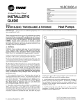
Heat Pumps
with this unit.
Please
return
to service
infbrmation
pack
TOP DISCHARGE --- UNRESTRICTED
5 FT. ABOVE UNIT
A, GENERAL
NOTICE:
These
outdoor
units,
except
for the TWPO6OD,
may be used
with
indoor
units
equipped
with
Capillary
Tube,
Thermostatic
Expansion
Valve
or the Accutron
TM
Flow
Control
Check
Valve
(F.C.C.V.)
assembly
for refrigerant
flow control.
The TWP06OD
outdoor
units
are only
approved
with
indoor
units
equipped
with
thermostatic
expansion
valve
refrigerant
controls.
Check for transportation
promptly, to the carrier,
damage after unit is uncrated.
any damage found to the unit.
Report
To determine
the electrical power requirements
of the unit, refer
to the nameplate
of the unit. The electrical power available must
agree with that listed on the nameplate.
The Weathertron
®Heat Pump has been designed and manufactured to withstand
and operate
in severe winter conditions.
However, there are precautionary
steps which should be taken at
the time of installation
which will help assure
the efficient
operation of the unit. It is recommended
that these precautions be taken
for units
being
installed
in areas
where
snow accumulation
and prolonged
below freezing
temperatures
occur.
1. Units should be elevated 3 to 12 inches above the pad or
rooftop, depending on local weather.
This additional
height will
allow be tter dra inc_ge of snow and ice (melted during d@x)st cycle)
prior to its refbeezin_.
This should prevent a build-up of ice
around the unit which occurs when unit is not elevated.
Insure
that drain holes
in unit base pan are not obstructed
preventing
draining
of defrost
water.
2. If possible, avoid locations that are likely to accumulate
snow
drif_bs. If not possible, a snow drif_b barrier should be installed
around the unit to prevent a build-up of snow on the sides of the
unit and should be of sufficient distance from the unit to prevent
restriction
of airflow to and fi'om the unit. Also allow for proper
maintenance
space. The barrier should be constructed
of materials which will blend in with the building design.
3. Avoid locating the unit where condensation
and freezing of
deli'ost vapor may annoy the customer.
For instance, installing
the unit under a bedroom, kitchen, or picture window may be
annoying
to the customer since condensate
and fog will occur
during the defrost cycle.
4. Avoid locating the unit under the eaves or other overhead
structures
as sizeable icicles may form and the unit may be
damaged by these falling icicles.
Since the manufacturer
has a policy of continuous
product improvement,
it reserves the right to change
specifications
and design without notice
© American
Standard
Inc.
1999
I
;TALLER'S
B. LOCATION
& PREPARATION
G
OF THE UNIT
1. The unit should be set on a level support
as the unit base pan.
BRAZE
pad at least as large
3. The top discharge area must be unrestricted
(5) f_et above the unit.
for at least
five
NOTE: Consult
in elevation
Ref)'t:erantPtpuzgSoflware
should
not exceed
,Pub.No.
ADAPTER
\
(F.C.C.V.)ORtFICE
/
9. Determine
if adequate power supply is available
according to nameplate
specifications.
AS SHIPPED
with
and correct
[_
CONTROL
VALVE
_:--------LIQUID
LINE
FIELD SUPPLIED
requirements.
This should be thoroughly
ordering refrigerant line sets.
The gas line nmst always
checked out befbre
be insulated.
The units are factory charged with the system charge required
when using fil_een (15) feet of connecting line. Unit nameplate
charge is the stone. Final refrigerant
charge adjustment
is
necessary,
use the Charge Charts in the outdoor unit Service
Facts.
1. Determine
10. Install the unit in accordance with national, state, and local
codes.
FLOW
_
sixty
8. A pull-thru hole for the refrigerant lines should be provided
of sufficient size to allow the passage of both liquid and suction
lines.
C. ACCUTRON
FLOW CONTROL
CHECK VALVE
to
_2-3312-01.
7. Locate and install indoor coil or blower coil in accordance
instruction
included with that unit.
TM
CAP
BODY
length of refrigerant
lines from outdoor
NOT exceed sixty (60) f_et.
diffbrence
END
COMPONENTS
ACCUTRON_M
4. When the outdoor unit is mounted on a roof, be sure the roof
will support
the unit's weight.
Properly
selected vibration
isolators are recommended
to prevent transmission
to the building structure.
6. Maximum
(60) feet.
iNDOOR
SEALING
2. The support
pad must NOT be in direct contact with any
structure.
The unit must be positioned a minimum of 12" from
any wall or surrounding
shrubbery
to insure adequate airflow. A
30" clearance must be provided in front of control box (access
panels) & any other side requiring
service access to meet National Electrical
Code. The unit must be far enough away from
any structure
to prevent excess roofrun-offwater
from pouring
directly on the unit.
5. The maximum
indoor unit should
TYPE
2. Consider
the most practical
types
of bends
NOTE: Large diameter
it has been shc:ped.
way to run the lines.
to be made and space
tubing will be very: di[ficult
limitations.
to rebend once
If the indoor unit System
Refrigerant
Flow control is an
Aecutron TM orifice and check valve assembly,
an orifice size
change may be necessary.
3. Determine
tubing-INSIDE
The outdoor model determines the required orifice size. Check
the listed orifice size on nameplate of the selected outdoor model.
If the indoor u nit is factory shipped with a diffbrent orifice size,
the orifice must be changed to obtain system rated performance.
4. Provide a pull-thru
hole of sufficient size to allow both liquid
and gas lines plus fittings to clear. The location of this hole (if
practical) should be just about the wall plate which is resting on
the fbundation.
IMPORTANT:
The outdoor
unit
is shipped
with
the
proper
size orifice
and a stick-on
orifice
size label in an
envelope
attached
to the outdoor
unit.
Outdoor
unit
nameplate
will have correct
orifice
size specified
as
BAYFCCV
--- A for rated
performance.
5. Be sure the tubing
D. INSTALLING
REFRIGERANT
the tubing
point for routing the refrigerant
THE STRUCTURE.
is of sufticient
length.
--- do not kink or dent.
7. Route the tubing maMng all required
bends
secure the tubing before making connections.
and
properly
LINES
Pressure taps are provided on the service valve plate and on
service valve of outdoor unit for compressor suction and liquid
pressures.
The indoor end of recommended
refrigerant
line sets may be
straight
or with a 90 degree bend, depending
upon situation
PAGE 2
6. Uncoil
the best starting
OR OUTSIDE
8. To prevent
a noise within
the building
structure
due to
vibration transmission
from the refrigerant
lines, the following
precautions
should be taken:
a. When the refrigerant
lines have to be fastened
to floor
joists or other framing in a structure,
use isolation type hangers.
Pub. No. 18-BC28D11-4
STALLER'S
3. Insulate
®
LIQUID LINE SERVICE VALVE
the entire
GUI
gas line and its fittings.
4. Do NOT allow uninsulated
contact with bare gas line.
liquid
line
to come in direct
5. Precautions
should
be taken
to avoid
heat
damage
to
the pressure
tap valve
core
during
brazing.
It is recommended
that the pressure
tap port valve
core be removed
and a wet rag wrapped
around
the valve
body.
UNIT SiDE OF
SERVICE VALVE
NOTICE:
LIQUID
LINE
HEX HEADED
VALVE
SYSTEM_
CONNECTION
RETAINING
pressure
Use
care
tap
port,
to make
while
sure
wet
that
rag
no
moisture
is being
enters
used.
6. Remove braze shield from clear plastic bag. Soak pad in
water and place over suction and liquid lines to protect unit
finish. See Figure 5. Discard pad when finished with brazing.
7. Use a Dry Nitrogen
Purge and Brazing Alloy without flux
when brazing the field line to the copper factory connection.
Flow
dry nitrogen into either valve pressure tap port, thru the tubing
and out the other port while brazing.
RING
8. Braze using accepted good brazing techniques.
b. Isolation hangers
should also be used when
lines are run in stud spaces or enclosed ceilings.
c. Where the refrigerant
lines run through
should be insulated
and isolated.
d.
Isolate
E. SERVICE
refrigerant
LEAK
a wall or sill, they
BRASS
LIQUID
OPERATION
IMPORTANT:
fore attaching
OPERATION
AND
GAS
LINE
SERVICE
VALVE
The Service Valves are factory shipped in the seated position to
hold factory charge.
The pressure
tap service port (when depressed) opens only to the field brazing side of the valve when the
valve is in the seated position. The liquid line valve is not a back
seating valve (see WARNING
below).
WARNING:
CAM TI ON: Inscroncompressor
applications,
dome
temperatures
may be
compressor,
may cause minor
the lines fl'om all ductwork.
VALVE
CHECK
BALL
SERVICE
The Gas Line Service Valve is full open with a 1/4 turn counterclockwise.
See Figure 4.
REFRIGERANT
minimizing
Pub. No. 18-BC28D11-4
valve
core
be-
GAS LiNE SERVICE
VALVE
CAP_._8
114 TURN
ONLY
COUNTERCLOCKWISE
_--
VALVE
STEM
UNITSIDE
VALVE
/
PRESSURE
TAP
PORT
GAS
CAP_
LINE
CONNECTION
&
LINES
1. Boil)re brazing,
remove plugs
tubes. (?lean internal
and external
to brazing.
2. Cut and fit tubing
port
VALVE
The Brass Gas Line Ball Service Valve is shipped in the closed
position to hold the factory refrigerant
charge. The pressure tap
service port (when depressed) opens only to the field brazing side
when the valve is in the closed position.
BRAZING
tap
of
After brazing operation of refrigerant
lines to both the outdoor
and indoor unit is completed, the field brazed connections must
be checked for leaks. Pressurize
through the service valve ports,
the indoor unit and field refrigerant
lines with dry nitrogen to
360 psi. Use soap bubbles or other leak-checking
methods to see
that all field joints are leak-free! If not, release
pressure;
then
repair!
OF
GAS LINE
Replace
pressure
hoses
for evacuation.
top
Extreme
caution
should
beex-
ercised
so the internal
steel stem retaining
ring is not
damaged by backing
out the valve stem when opening
the
valve.
If the valve stem is forced
out past the retaining
ring, system pressure
could force the valve stem out of the
valve body. If the retaining
ring is missing,
do not attempt
to open the valve.
See Figure
3.
BRASS
hot. Do not touch
to severe burning.
from external
copper stub
surfaces of stub tubes prior
the use of sharp
90 ° bends.
CORE
PAGE 3
I
;TALLER'S G
to ()pen gas line valve. An Adjustable
or 314" Open End wrench
is required to take off the valve stem crop.
HEAT SHIELD
O
9. The liquid line shut-off valve can now be opened. Remove
shut-off' valve cap. Fully insert hex wrench into the stem and
baekou t counterclockwise until valve stem just touches retainer
ring (approximately five (5) turns) observing WARNING statement. See Figure 3.
o
10. Replace liquid service pressure tap port cap and valve stem
cap. These caps MUST BE REPLACED to prevent leaks.
Replace valve stem and pressure tap cap finger tight, then
tighten an additional 1/6 turn.
11. The gas valve can now be opened.
Open the gas valve by
removing the shut-offvalve
cap and turning the valve stem 1/4
turn counterclockwise,
using 1/4" Open End orAdjustable
wrench.
See Figure 4.
12. The gas valve is now open fbr refrigerant
stem cap to prevent leaks. See Figure 4.
flow. Replace
valve
If refrigerant
lines are longer than 15 f>et and!or a different size
than recommended,
it will be necessary to adjust system refrigerant charge upon completion
of installation.
F. ELECTRICAL
SYSTEM
EVACUATION
CONNECTIONS
WARN
NOTE: Since the outdoor unit has a refi'igerant
and liquid line valves must remain closed.
charge,
the gas
this equipment,
tions to avoid
IN G: When
installing
or servicing
ALWAYS exercise
basic safety precauthe possibility
of electric
shock.
1. Upon completion ofleak check, evacuate the refi'igerant lines
and indoor coil before opening the gas and liquid line valves.
1. Power wiring and grounding of equipment
local codes.
must comply with
2. Attach appropriate
hoses
liquid line pressure
taps.
2. Power
supply
nameplate.
3. Install
a separate
from mani%ld
gauge
to gas and
NOTE:
Unnecessary
switching
of hoses cart be avoided and
complete evacuation of all lines leading to sealed system cart be
accomplished
with mani[bld center hose and connecting branch
hose to a <ylinder of HCFC-22 and vacuum pump.
3. Attach
center
hose of mani%ld
gauges
to vacuum
pump.
4. Evacu ate until the micron gauge reads no higher than 350 microns.
5. Close off valve to vacuum
pump and observe the micron
gauge. Ifgau ge pressure rises above 500 microns in one (1) minute,
then evacuation
is incomplete
or system has a leak.
4. Ground
must
agree with equipment
disconnect
the outdoor
switch
at the outdoor
unit.
unit per local code requirements.
5. Provide flexible electrical conduit whenever vibration
mission may create a noise problem within the structure.
trans-
6. The use of color coded low voltage wire is recommended
to
simplif_¢ connections
between the outdoor unit, the thermostat,
and the indoor unit.
Table 1 --- NEC Class II Control
Wiring
24 VOLTS
WIRE SIZE
MAX. WIRE LENGTH
*22 AWG
30 FT.
7. With a vacuum pump and micron gauge blanked off, open
valve on HCFC-22 cylinder and charge refrigerant
lines and
indoor coil with vapor to tank pressure
of HCFC-22 supply.
20 AWG
100 FT.
18 AWG
150 FT
NOTE:
DO
ATMOSPHERE.
16 AWG
225 FT.
14 AWG
300 FT.
6. If vacuum gauge does not rise above 500 microns
(1) minute, the evacuation
should be complete.
NOT
VENT
REFRIGERANT
INTO
in one
THE
8. Close valve on HCFC-22 supply cylinder.
Close valves on
manifbld gauge set and remove refrigerant
charging hoses fi'om
liquid and gas pressure
tap ports.
NOTE:
A 3/16" Allen wrench is required
service valve. A 1/4" Open End or Adjustable
PAGE 4
*If 22 AWG is used, make
sure it is high
quality
wire.
to open liquid line
wrench is required
Pub. No. 18-BC28D11-4
STALLER'S
7. Table i defines maximum total length of low voltage
from outdoor unit, to indoor unit, and to thermostat.
wiring
GUI
2. TST = Test (Shorting TEST_COMMON
up all defi'ost board timings.)
to this pin speeds
8. Mount the indoor thermostat
in accordance
with instruction
included with the thermostat.
Wire per appropriate
hook-up
diagram (included in these instructions).
3. FRC_DFT = Forced Defi'ost (ShortTEST
COMMON to this
pin for two (2) seconds to initiate a forced defl'ost. Remove the
short affuer defi'ost initiates.)
G. ELECTRICAL
DEFROSTCONTROLCHECKOUT
HEATERS
Electric heaters,
if used, are to be installed in the air handling
device according to the instructions
accompanying
the air handler and the heaters.
H. START
KIT
All single phase units, except TWP060D,
ponents which are factory installed.
I.
OUTDOOR
have quick start
com-
Normal
operation
a. LED on
b. 24V AC
c. 24V AC
d. Defrost
TESTCOMMON
If a defl'ost
information
THERMOSTAT
requires:
board flashing I time/second.
between R & B.
between Y & B with unit operating.
initiation
when FRC_DFT
pin is shorted
pin.
control problem
in control box.
is suspected,
WARNING:
to
ref>r to the service
DoNOTconnect24VAC
toT1
An outdoor thermostat
TAYSTAT250A
may be field installed.
For data see wiring diagrmn
attached
to unit and instruction
sheet packaged with outdoor thermostat.
(ODS-A)
J. DEFROSTCONTROL
K. OPERATIONAL
The demand defrost control measures
heat pump outdoor ambient temperature
with a sensor located outside the outdoor coil.
A second sensor located on the outdoor coil is used to measure the
coil temperature.
The difference between the ambient and the
colder coil temperature
is the ditI_rence
or delta-T measuremerit. This delta-T measurement
is representative
of the operating state and relative capacity of the heat pump system.
By
measuring
the change in delta-T, we can determine
the need for
defi'ost. The coil sensor also serves to sense outdoor coil temperature for termination
of the defi'ost cycle.
Final phases of this installation
are the unit Operational
and
Checkout Procedures
which are found on page 8 of this instruction.
FAULT
DETECTION
A fault condition is indicated by the flashing light on the defl'ost
control inside the heat pump control box.
In normal operation, the defl'ost control light will flash once each
second. If the light is flashing more than once per second or notat-all, refer to the service manual for that unit.
PIN IDENTIFICATION
(See Figure
L. COMPRESSOR
ODS-A
thermistor
AND CHECKOUT
SUMP
WILL
BE BLOWN.
PROCEDURES
HEAT
After all electrical wiring is complete, SET THE THERMOSTAT
SYSTEM SWITCH IN THE OFF POSITION SO COMPRESSOR
WILL NOT RUN, and apply power by closing the system main
disconnect switch. This will activate the compressor sump heat.
Do not change the Thermostat
System Switch until power has
been applied long enough to evaporate any liquid of HCFC-22 in
the compressor
(30 minutes for each pound of HCFC-22 in the
system as shown on the nameplate).
Following this procedure
will prevent compressor
damage at the initial startup.
Record the "POWER APPLIED DATA" on the designated
below:
lines
6)
1. TEST_COMMON
(Shorting any of the other pins to this pin
causes the function of the other pin to be executed. Leaving this
pin open results in the normal mode of operation.)
®
terminal.
Time
A.M./P.M.
Date
By
PiN IDENTIFICATION
Electrician
(SEE WIRING
Z
DIAGRAMS
)
o
o
o
I.0_
I
LL
a t
LL
Pub, No, 18-BC28D11-4
PAGE 5
I
;TALLER'S G
A TYPICAL
FIELD WiRiNG DIAGRAM FOR SPLIT SYSTEM
TWP018=060 WITH AiR HANDLERS
A TYPICAL FIELD WIRING DIAGRAM
WITH VARIABLE SPEED AIR HANDLERS
HEAT PUMPS
FOR TWP018-060
HEAT PUMPS
AND SUPPLEMENTARY
HEATERS
NOTES:
1. POWER W_RING AND GROUNDING
LOCAL CODES.
2. BE SURE POWER
3. LOW VOLTAGE
4.
USE COPPER
SUPPLY
WIRING
AGREES
TO BE NO
CONDUCTORS
OF EQUIPMENT
WITH
EQUIPMENT
18 AW.G.
/F i U'i
MUST COMPLY WITH
MINIMUM
s,O0 bl i I!bl0_
BA?28}', 38
NAMEPLATE
C0[}S
A
CONDUCTOR
ONLY.
5. POLARIZED PLUG SECTION PM-A iS ATTACHED TO HEATER CONTROL
BOX. SECTION 1-PF IS FACTORY WIRED INTO AIR HANDLER.
6. TERMINAL W2 WILL HAVE INTERNAL
CONNECTIONS
ONLY IF SECOND
CONTACTOR
IS USED BY THE HEATER
CONTROLLING
POWER TO ELECTRIC
HEATING ELEMENTS
IF SECOND (BH)
CONTACTOR
IS USED, THEN FIELD
CONNECTIONS
TO W2 CAN BE
OMITTED
H #
_,
0, J) JC I (N
SNLE ''E
Pr4 s_
I
'pi
............
,i
}
_/'
8E
[OT8
AS APPROPRIATE
IOTE
I
7. IF ODT iS NOT USED. THEN CONNECT
APPROPRIATE
JUMPER FROM W1 TO
W2 ON LVTB
9. CONNECT IN THIS MANNER
UNiT HAS "F" CONNECTION
O
NOlES
8. IF HUMIDISTAT
IS NOT USED,
CONNECT JUMPER FROM "R" TO "BK"
FOR FULL TONNAGE AIRFLOW IN
COOLING
6 & Z
,_;[;-IA
}[ R
IF OD
IIUMI) _TAi
N0][ 8
10. CONNECT W3 TO W2 ONLY IF USING
HEATER WITH 3 HEATER STAGES
=C:
.......
]
_g> W;li N0
....................................
4 '/
_
'_Y[;
]
',':;" WI, N0
PAGE 6
If
From Dwg. 21B800255
Rev. 2
Pub. No. 18-BC28D11-4
STALLER'S
TWP018=060
OUTLINE
DRAWING
NOTE: ALL DIMENSIONS
_EFV
E
D
_]CAL
COMRONE
PEr
PFiEVA
CE
A
El
AX
q
ii
ii
II
II
!!
II
ii
_-<:
!!
II
ii
iiII iiII
JJ
II
JJ
II
ii
II
(2}
A
II
JJ
II
ii
II
_
m
GAS L [bE
"D"()
J), F
CONNECTION
\\\\\\
t:
"
FG,
i Q;J]D
[:'_O,D,
(ONNEC
PR-SSURE
I
_
8
FI@_ 2
]QUID
O,D,
ONNE',
i
ARE
J,
I
VE
l)
S/\E
F[
ARE
]NG
A
i
1
12)' i (:N
t
SER,/[CE
Y/4
_SA : E% AZ
'H]TB
/4"
]NE
S RV](E
VA
VE,
FEMA
E BRAZED
ION
W II
I/4"
SA
:
_AP
Y
'NG,
GAS LINE BALL SERVICE VALVE,
BALL 1/4 TURN "D" O.D. FEMALE
BRAZED CONNECTION WITH 1/4"
SAE FLARE PRESSURE TAP FITTING
(9)
/O:
O_SCI_ARG
AF_EA
S40UI
D
LNR
S[IRK}IED
IOR
AI
[
A}I
VE
(B)
E T ABOV
L
IT.
L
',T SIq©LL
D BE
Pl AD
) SO RDO
RUN
Oi F 7FA E:/
DOES
NOT
POJR
D RECTI
Y ON dN
,
AN[}
SI(}("
B
A
EAS'
0%
( _'_
ROM
WA[
AND
A
S(R
0[
O NB
5ilRUBBERY
ON TWO SIDES,
OT
LR
I W 0 S )E S U
E S R '_C I E D.
JJ
\_
I
4
IN MM (INCHES).
}-_
AND
RE
R_GE
S C ARANCE%
]NO COD,
229
GUI
[NE
SERV
CE
VA
VE,
EMA
E BRAZED
] '01
A'] H
/4 _ SAE
NRESSJR
lAP
TT]NC
MODELS
FIG.
A
B
C
D
E
TWP0 ! 8C
1
24-3/8
28-1/4
24-5/8
5/8
1/4
TWP024C
2
28-5/8
32-7/8
28-3/4
3/4
5/18
TWP030D
2
32-3/4
32-7/8
28-3/4
3/4
5/18
TWP036C
2
37
38-7/8
34-3/4
7/8
3/8
TWP042C
2
37
38-7/8
34-3/4
7/8
3/8
TWP048C
2
37
38-7/8
34-3/4
1-1/8
3/8
TWP060D
2
37
38-7/8
34-3/4
1-1/8
3/8
NOTE: TABLE IN INCHES ONLY.
From Dwg. 21D147562
Pub, No, 18-BC28D11-4
Rev. 6
PAGE 7
I
;TALLER'S G
CHECKOUT
After installation
following list:
has been completed,
1. Refrigerant
that the entire system
be checked
against the
[
]
[
]
[
]
4. Have passages through masonry been sealed? If mortar is used, prevent mortar from
coming into direct contact with copper tubing .....................................................................................
[
]
5. Indoor coil drain line drains freely.
[
]
[
]
[
]
8. Thermostat thermometer
is accurate. Check against a reliable thermometer.
Adjust
per instructions with thermostat ..........................................................................................................
[
]
9. Is correct
[
]
2. Suction
Line, Leak checked
PROCEDURE
it is recommended
Lines and Fittings properly
3. Have all Refrigerant
6. Supply
..........................................................................................................
registers
insulated
Lines been secured
......................................................................................
and isolated
properly?
Pour water into drain pan .............................................................
and return grilles open and unobstructed
7. Return air filter installed
........................................................
.................................................................
......................................................................................................................
speed tap being used?
(Indoor blower
SYSTEM
motor)
....................................................................
OPERATIONAL
CHECK
IMPORTANT: To prevent compressor damage which may result from the presence of LIQUID refrigerant in the
crankcase, these procedures should be followed at initial Start-Up and at anytime the power has been off for 12 hours
or more.
1. Before proceeding with this "Operational Check," go to "Compressor Sump Heat Section" of this instruction to
determine the time compressor heat has been "ON," and make entry d the designated lines, in Step 2.
2. Start-Up Time
A.M./P.M.
Time Lapse
Power Applied Time
Hours
A.M./P.M.
Minutes.
3. If Steps 1 and 2 cannot be used, then place thermostat's system switch in the "OFF" position and apply power
by closing system disconnect switch. This energizes compressor heat and evaporates the liquid in the
crankcase. TO EVAPORATE LIQUID ALLOW AT LEAST ONE-HALF HOUR PER POUND (HCFC-22), AS
SHOWN ON UNIT NAMEPLATE.
OPERATING PRESSURES: After the unit has operated in the cooling mode for a short period of time, install
pressure gauges on the gauge ports of the discharge and suction line valves. Check the suction and discharge
pressures and compare them to the normal operating pressures provided in the unit's Service Facts.
NOTE: Use the pressures from Service Facts to determine the unit refrigerant charge.
To charge the system accurately, use superheat charging, or pressures
depending on flow control.
4. Except as required for safety while servicing:
SUPPLEMENTARY
HEATERS CHECKOUT
DOES HEATER
1. Be sure the fused disconnect
3. Check fuses for proper size per nameplate
NOTE:
OPERATION
PROCEDURES,
REQUIRE A SEPARATE
SWITCH.
IF USED
CIRCUIT?
and grounding
specifications
according
to codes ....................................
.....................................................................
in place and secured ..................................................................................
OF HEATERS
SYSTEM.
DISCONNECT
switch is "OFF," and safety label (if any) is attached ................................
2. Check on field wiring for sound connections
4. Check control box panel --
DO NOT OPEN SYSTEM
MUST BE CHECKED
DURING THE OPERATION
]
[
]
[
]
[
]
CHECK OF THE TOTAL
The Trane Company
6200
Technical Literature- Printed in U.S.A.
PAGE 8
[
Troup
Highway
TX 75707
Pub. No. 18-BC28D11-4
Tyler,
P.I.