1
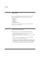
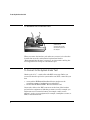
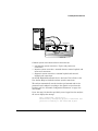
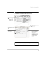
H
Broadband Service Analyzer
Setting Up the
STM-1 Electrical
Interface Pod
Copyright
Notice
Warranty
Printing history
© Hewlett Packard Australia Ltd 1996
All rights reserved.
The information contained in this document is subject to change without notice.
HEWLETT-PACKARD MAKES NO WARRANTY OF ANY KIND WITH REGARD TO THIS MATERIAL,
INCLUDING, BUT NOT LIMITED TO, THE IMPLIED WARRANTIES OF MERCHANTABILITY AND FITNESS
FOR A PARTICULAR PURPOSE.
Hewlett-Packard shall not be liable for errors contained herein or for incidental or consequential damages
in connection with the furnishing, performance, or use of this material.
A copy of the specific warranty terms applicable to your product and replacement parts can be obtained
from your local Sales and Service Office.
New editions of this guide are issued to reflect extensive changes made to the application. Revisions may
be issued between application versions to correct errors in the manual. There may not be a new edition
issued in conjunction with every application version release. The application version at the date of
printing is noted in the following table.
Manual Name:
Setting Up the STM-1 Electrical Interface Pod
Manual Part Number:
E5123-90001
Product Model Number: HP E5123A
Edition
1
1a
Product support
Printing Date
May 1996
February 1997
Hewlett Packard Australia Ltd
Australian Telecom Operation
PO Box 221
Blackburn, 3130
Victoria, Australia
Printed in Australia
Application Version
A.01.20
A.01.60
We want to hear from you. If you have any
comments, questions, or suggestions about our
documentation or support, send them to:
Email: [email protected]
Fax: +61 3 9210 5570
Phone: +61 3 9272 8633
Contents
Guide to the HP E5200A Broadband Service Analyzer Documentation ........
About the STM-1 Electrical Interface Pod.......................................................
Online Help ........................................................................................................
To Access User Online Help.........................................................................
Front Panel at a Glance ....................................................................................
To Set Up the Interface Pod ............................................................................
To Insert the Interface Pod..........................................................................
To Remove the Interface Pod ......................................................................
To Connect to the System Under Test .......................................................
Automatic Configuration Parameters..........................................................
To Manually Configure the Interface Pod ..................................................
What to Do Next................................................................................................
Standards and Specifications ...........................................................................
Communications Standards ........................................................................
Input and Output Specifications..................................................................
Physical Specifications ................................................................................
Environmental Specifications ......................................................................
Error Generation Specifications ..................................................................
iv
1
2
2
3
4
5
6
6
8
9
10
11
11
12
13
13
13
iii
Guide to the HP E5200A Broadband Service Analyzer Documentation
Guide to the HP E5200A Broadband Service
Analyzer Documentation
The HP E5200A Broadband Service Analyzer comes with a comprehensive set
of paper and online documentation. Use the following table to determine
which documents you should use.
What is it?
What does it do?
User’s Guide
•
•
•
•
•
Online Help
Who is it for?
contains instructions on how to set all users
up and install the analyzer
provides an outline of the most
common functions
describes the online help
provides an outline of the most
common system administration
functions
lists electrical, mechanical, and
environmental specifications
three volumes–User, Macro, and UPE all users
Compatibility–contain information
about, and instructions for using, the
analyzer
Quick Reference provides a quick overview of the
all users
analyzer's main features and functions
iv
Setting Up the
Interface Pod
guides
a series of guides that provide
descriptions of, and instructions for
installing, individual interface pods
all users will refer
to at least one of
these guides
Worldwide
Support card
provides information about support,
service, and warranty
all users
Release Notice
provides information not available
when this guide was printed
all users
About the STM-1 Electrical Interface Pod
About the STM-1 Electrical Interface Pod
Overview
The HP E5123A STM-1 Electrical Interface Pod is a self-contained, plug-in
module. You use it in conjunction with the HP E5200A Broadband Service
Analyzer to test and analyze a system under test (SUT).
In the transmit direction, the interface pod
•
•
•
automatically calculates and inserts Section/Regenerator Section BIP,
Line/Multiplexer Section BIP, and Path BIP
maps the ATM cells into the Virtual Container (VC)
automatically generates the framing pattern
In the receive direction, the interface pod
•
•
•
•
•
uses the A1 A2 framing pattern to frame align the electrical signal
applies frame descrambling
carries out pointer processing to align to the VC
detects line errors using the Section/Regenerator Section BIP,
Line/Multiplexer Section BIP, and Path BIP
extracts ATM cells and passes them to the measurement system
Hot swap and
automatic
configuration
Use the “hot swap” feature to insert and remove the interface pod while
the analyzer’s power is switched on. The analyzer automatically detects
the insertion of the interface pod and configures itself accordingly.
Immediately after you connect the interface pod to the SUT, the analyzer
automatically configures the receive and transmit parameters according to
the signal it receives.
Operating modes
The interface pod has four operating modes: full-duplex, transmit
loopback, receive loopback, and regenerator.
Components
The interface pod is shipped with
•
•
Application
a Calibration Certificate
this set up guide
The HP E5123A STM-1 Electrical Interface Pod requires an E5200A base
unit with Application Version number A.01.2 or greater.
1
Online Help
Online Help
The User Online Help provides all the information you need to use the
analyzer. Use the following sections to learn how to perform tasks:
•
•
•
•
•
•
Getting started
Monitoring
Capturing
Running tests
Simulating
System administration
Use the Reference section to find information about framing formats,
alarms, errors, and measurements.
To Access User Online Help
There are four ways to access information in the User Online Help.
2
•
Click the Help button that appears on most screens and windows to
display information about that screen or window.
•
From the main screen Help menu, select User to display the User Contents
screen.
•
Press F1. If the cursor is in an input field, you see help for that field;
otherwise you see the User Help Contents screen.
•
Press Shift+F1, or from the main screen Help menu, select Help on Item,
to change the mouse pointer into a question mark (?). Move the question
mark around the screen and place on the item for which you want help;
then click the mouse. Use this option to get help on non-input fields.
Front Panel at a Glance
Front Panel at a Glance
Access
(green LED) Lights each time the interface pod is accessed by the
network.
Signal
(yellow LED) Lights when a valid signal is present at the input connector.
In
(BNC) Accepts an electrical signal from the SUT.
Out
(BNC) Provides a signal to the SUT.
3
To Set Up the Interface Pod
To Set Up the Interface Pod
Caution
Handle the interface pod with care to avoid electrostatic discharge (ESD)
damage during unpacking, installation, and operation. The connectors on
the front and rear of the interface pod are susceptible to ESD.
1 Insert the interface pod into the analyzer.
See “To Insert the Interface Pod” on page 5. The procedure is the same for
all interface pods.
2 Connect the interface pod to the SUT.
See “To Connect to the System Under Test” on page 6. The analyzer
automatically recognizes and configures the interface pod.
3 If you want to change any of the configuration parameters, see “To
Manually Configure the Interface Pod” on page 9.
4
To Set Up the Interface Pod
To Insert the Interface Pod
You can insert and remove interface pods at any time, even when the
analyzer is powered on. Initially, you insert an interface pod when you set
up the analyzer. Subsequently, you insert an interface pod when you
change the physical layer interface that you want to monitor.
1 Hold the interface pod with the front panel connectors facing you and
the Hewlett-Packard logo facing upwards.
2 Insert the interface pod into Port 1 or Port 2 of the analyzer.
3 Push the interface pod firmly into the analyzer until the connector at
the rear is properly seated. The clip on the base of the interface pod
clicks into place when the interface pod is fully inserted.
Caution
You must always have two interface pods inserted in the the HP E5200A
Broadband Service Analyzer while it is operating. If your operations
require only a single interface pod, insert the blank interface pod
(provided with the analyzer) into the other port. The two interface pods
are necessary to maintain a balanced airflow for cooling of internal
components and to comply with EMC standards.
5
To Set Up the Interface Pod
To Remove the Interface Pod
Gently press on the clip
underneath the
interface pod and pull
the interface pod out of
the analyzer.
When you remove the interface pod, make sure you store it in a dust free
location that meets the environmental requirements listed in
“Environmental Specifications” on page 13. An electrostatic-safe bag has
been supplied for the storage of each interface pod.
To Connect to the System Under Test
Obtain a pair of 75 Ω coaxial cables with BNC connectors. Before you
connect the interface pod to the system under test (SUT), ensure that you
have
•
•
connected the HP E5200A Broadband Service Analyzer to the
controlling computer (workstation or notebook PC)
inserted the HP E5123A STM-1 Electrical Interface Pod
Connect the cables to the BNC connectors on the front of the interface
pod and to the equipment or link that you want to test. For example, you
might want to test a network element (for example, switch, service
gateway), service access equipment (for example, a multiplexer, router, or
PAD), or transmission link.
6
To Set Up the Interface Pod
Receive (Rx)
Transmit (Tx)
Receive (Rx)
Common system connections and test connections are
•
•
•
non-intrusive system connection—T-piece and passive test
connections
intrusive system connection—network element, remote loopback, and
in-line test connections
diagnostic system connection—transmit loopback and external
loopback test connections
See the HP E5200A Broadband Service Analyzer User’s Guide or the
User Online Help for details about these system connections.
The analyzer automatically sets the interface pod transmit and receive
parameters and configures according to the signal it receives from the
interface pod. See “Automatic Configuration Parameters” on page 8 for
more details.
If you “hot swap” the interface pod while you are logged in to the analyzer,
the screen displays the message
Auto configuring, please wait...
Automatically configuring physical interfaces and
protocols according to the monitored signal.
7
To Set Up the Interface Pod
Automatic Configuration Parameters
After you insert the interface pod and connect it to the SUT, the analyzer
automatically configures to the STM-1 electrical signal.
The analyzer sets the remaining physical layer receive and transmit
parameters to the following defaults:
•
•
•
See also
8
reference (internal) clock
20 dB input gain off
full duplex
User Online Help contains information about the ATM layer automatic
configuration parameters.
To Set Up the Interface Pod
To Manually Configure the Interface Pod
1 From the Configure
menu, select the
appropriate port;
then select Set Up.
2 Click the STM-1 tab.
3 Select the parameters
you require.
4 Click to set the
configuration
or
Click Auto to set the
parameters to the default
settings. A message
warns you that the
reconfiguration will cause
some measurements and
data to be lost and asks if
you want to continue.
Click OK.
Note When the configuration is complete, the analyzer updates all relevant screens and
windows to reflect the new configuration parameters.
9
What to Do Next
What to Do Next
The interface pod is now ready for use.
See the User Online Help to find out the different tasks you can perform
using the analyzer and interface pod.
10
Standards and Specifications
Standards and Specifications
Communications Standards
ITU-T G.703
Physical/Electrical Characteristics of Hierarchical Digital Interfaces
ITU-T G.708
Network Node Interface for the Synchronous Digital Hierarchy
ITU-T G.709
Synchronous Multiplexing Structure
ITU-T I.432
B-ISDN User-Network Interface—Physical Layer Specifications
ITU-T G.825
The control of jitter and wander within digital networks which are
based on the synchronous digital hierarchy
ATM Forum UNI 3.1
ATM User-Network Interface (UNI)
Bellcore GR-253-CORE
Synchronous Optical Network (SONET) Transport Systems: Common
Generic Criteria (a module of TSGR, FR-440)
11
Standards and Specifications
Input and Output Specifications
Transmit Levels
Parameter
Nominal
Min.
Max.
Signal level
1.0 V (pp)
0.9 V (pp) 1.1 V (pp)
Line rate
155.52 Mb/s –4.6 ppm
+4.6 ppm
Line jitter
Notes
complies with ITU-T G.703
using internal frequency reference
complies with ITU-T G.825 (SDH),
Bellcore GR-253-CORE, and
Bellcore TR-TSY-000499 (SONET)
Receive Levels
Parameter
Sensitivity
Line rate
12
Nominal
Min.
Max.
13 dB
155.52 Mb/s –15 ppm
Notes
complies with ITU-T G.703
+15 ppm
Jitter tolerance
complies with ITU-T G.825 (SDH),
Bellcore GR-253-CORE, and
Bellcore TR-TSY-000499 (SONET)
Jitter transfer
complies with ITU-T G.825 (SDH),
Bellcore GR-253-CORE, and
Bellcore TR-TSY-000499 (SONET)
Standards and Specifications
Physical Specifications
Weight
1.0 kg ( 2.2 lbs) (nominal)
Dimensions
Height:
Width:
Length:
44 mm (1.73 inches)
149 mm (5.87 inches)
222 mm (8.74 inches) not including front panel connectors
236 mm (9.29 inches) including front panel connectors
Environmental Specifications
Parameter
Nominal
Min.
Max.
Notes
Operating Temperature
5 oC
(41 oF)
45 oC
(113 oF)
with two interface pods installed
Storage Temperature
–40 oC
(–40 oF)
70 oC
(158 oF)
Humidity
15%
90%
Altitude
at 40 oC (104 oF)
4.6 km
(2.86 miles)
Error Generation Specifications
Parameter
Nominal
Min.
Max.
Notes
Line error ratios
1 x 10 -9
1 x 10 -3
errors are added bit synchronously
and are accurate to 0.1% or better
FEBE ratio
1 x 10 -9
1 x 10 -3
errors are added bit synchronously
and are accurate to 0.1% or better
13
Certification
Hewlett Packard Australia Ltd certifies that
this product met its published specifications
at the time of shipment from the factory.
Hewlett-Packard (HP) further certifies that
its calibration measurements are traceable
to the extent allowed by the calibration
facilities of other International Standards
Organization members.
Warranty
The hardware is warranted against defects
in materials and workmanship. If HP
receives notice of such defects during the
warranty period, HP shall, at its option,
either repair or replace hardware products
which prove to be defective.
HP software and firmware products that
are designated by HP for use with a hardware product, when properly installed on
that hardware product are warranted not
to fail to execute their programming
instructions due to defects in materials and
workmanship. If HP receives notice of such
defects during the warranty period, HP
shall repair or replace software media and
firmware which do not execute their programming instructions due to such defects.
HP does not warrant that the operation of
the software, firmware, or hardware shall
be uninterrupted or error free.
If HP is unable, within a reasonable time,
to repair or replace any product to a condition as warranted, the Buyer shall be entitled to a refund of the purchase price upon
return of the product to HP.
For product warranties requiring return to
HP, this product must be returned to a
service facility designated by HP. Buyer
shall prepay shipping charges to HP (and
shall pay all duties and taxes) for products
returned to HP for warranty service. Except
for products returned to buyer from
another country, HP shall pay for return of
products to Buyer
Duration and Commencement of the
warranty
The hardware has a three year, return to
HP Service Centre warranty, commencing
at delivery date (type 7A).
The software and firmware has a 90 day,
replacement warranty commencing at
delivery date (type 3C).
Limitation of Warranty
The foregoing warranty shall not apply to
defects resulting from improper or inadequate maintenance by Buyer, Buyer-supplied products or interfacing, unauthorized
modification or misuse, operation outside
of the environmental specifications of the
products, or improper site preparation or
maintenance.
THE WARRANTY SET FORTH ABOVE IS
EXCLUSIVE AND NO OTHER WARRANTY,
WHETHER WRITTEN OR ORAL, IS
EXPRESSED OR IMPLIED. HP SPECIFICALLY DISCLAIMS THE IMPLIED WARRANTIES OF MERCHANTABILITY AND
FITNESS FOR A PARTICULAR PURPOSE.
Exclusive Remedies
THE REMEDIES PROVIDED HEREIN ARE
BUYER’S SOLE AND EXCLUSIVE REMEDIES. UNLESS REQUIRED BY APPLICABLE
LAW, IN NO EVENT SHALL HP BE LIABLE
FOR DIRECT, INDIRECT, SPECIAL, INCIDENTAL, OR CONSEQUENTIAL DAMAGES
(INCLUDING LOSS OF PROFITS) WHETHER
BASED ON CONTRACT, TORT, OR ANY
OTHER LEGAL THEORY.
Restricted Rights Legend
Use, duplication, or disclosure by the Government is subject to the restrictions as set
forth in subdivision (b)(3)(ii) of the Rights in
Technical Data and Computer Software
clause at 52.227-7-13. Hewlett-Packard
Company, 3000 Hanover Street, Palo Alto,
California 94304.
Additional Information for Test and
Measurement Equipment
If test and measurement equipment is
operated with unscreened cables and/or
used for measurements on open setups,
the user has to ensure that under operating
conditions the Radio Interference Limits are
still met at the border of the user’s premises.
Calibration
Hewlett-Packard recommends that this
equipment be recalibrated two years after
first use and at two-yearly intervals thereafter. The on-shelf period prior to first use
will not affect the calibration of this equipment. Call your local HP Service Representative for more information.
Warnings
DO NOT operate damaged
equipment Whenever it is possible that
The following general safety precauthe safety protection features built into this
tions must be observed during all
product have been impaired, either through
phases of operation, service, and
physical damage, excessive moisture, or
repair of this product. Failure to
any other reason, REMOVE POWER and do
comply with these precautions or
not use the product until safe operation can
with specific warnings elsewhere in
be verified by service-trained personnel. If
this manual violates safety stannecessary, return the product to a Hewlettdards of design, manufacture, and
Packard Sales and Service Office for service
intended use of the product.
and repair to ensure the safety features are
Hewlett-Packard Company assumes
maintained.
no liability for the customer’s failure
to comply with these requirements. DO NOT substitute parts or modify
equipment Because of the danger of
Ground the equipment For safety
introducing additional hazards, do not
Class 1 equipment (equipment having a
install substitute parts or perform any
protective ground terminal), an uninterruptunauthorized modification to the product.
ible safety ground must be provided from
Return the product to a Hewlett-Packard
the mains power source to the product
Sales and Service Office for service and
input wiring terminals or supplied power
repair to ensure features are maintained.
cable.
DO NOT clean with fluids
DO NOT operate the product in an
Doing so may make the equipment unsafe
explosive atmosphere or in the presfor use.
ence of flammable gases or fumes.
For continued protection against fire,
Safety Symbols
replace the line fuse(s) only with fuse(s) of
the same voltage and current rating and
type. DO NOT use repaired fuses or shortcircuited fuse holders.
Instruction manual symbol affixed to product. Indicates that the user must refer to
Keep away from live
the manual for specific Warning or Caution
circuits Operating personnel must not
remove equipment covers or shields. Proce- information to avoid personal injury, or
dures involving the removal of covers and damage to the product.
shields are for use by service-trained personnel only. Under certain conditions, dangerous voltages may exist even with the
equipment switched off. To avoid electrical
shock, DO NOT perform procedures involving cover or shield removal unless you are
qualified to do so.
Protective conductor terminal indicates the
field wiring terminal that must be connected to ground before operating the
equipment—protects against electrical
shock in case of fault.
Frame or chassis ground terminal—typically
connects to the equipment’s metal frame.
Earth (ground) terminal.
Alternating current (ac).
Direct current (dc).
Indicates hazardous voltages.
WA R N I N G
Calls attention to a procedure, practice, or
condition that could cause bodily injury or
death.
CAU T I O N
Calls attention to a procedure, practice, or
condition that could possibly cause damage
to equipment or permanent loss of data.
Indicates that antistatic precautions should
be taken.
Avertissement
Service et ajustement
Cet appareil répond aux normes de la
“Classe de sécurité 1” et est muni d’un fil
de mise à la terre pour votre protection.
Des “tensions dangereuses” résident dans
cet appareil. Par conséquent, le service et
l’ajustement doivent être effectué uniquement par une personne qualifiée.
Pour prévenir les risques de choc électrique, la broche de mise à la terre du
cordon d’alimentation ne doit pas être désactivée.
Restrictions d’utilisation
L’utilisateur se doit d’observer les mesures
de précaution énumérerais-dessous pour
toutes les phases d’utilisation, de service et
de réparation de cet appareil. Le fait de ne
pas s’y conformer équivaut à ne pas
respecter les mises en gardes spécifiques
contenues dans ce manuel et constitue une
violation des normes de sécurité relatives à
la conception, la fabrication et l’utilisation
prévue de cet appareil. La société HewlettPackard n’assume aucune responsabilité
envers un client qui manquerait de se conformer à ces exigences.
Ne remplacez pas de composantes lorsque
le cordon d’alimentation est sous tension. Il
pourrait y avoir présence de “tension dangereuses” même lorsque l’appareil est
déconnecté.
Manipulation du tube cathodique
Une manipulation brusque, ou le fait de
secouer l’appareil, peut provoquer le bris du
tube cathodique. L’implosion qui s’en suivrait entraînerait la dispersion à grande
vélocité d’éclats de verre. Le retrait ou
l’installation du tube cathodique ne doit
être exécuté que par un technicien qualifié,
portant un masque et des gants de sécurité
homologués.
Service non autorisé
L’installation de pièces étrangères, ou tous
modification apportée à l’appareil sans le
Afin de minimiser les risques de choc élec- consentement de Hewlett-Packard est
trique, le châssis et le cabinet de l’appareil formellement interdit. Le fait de procéder à
doivent être mis à la terre. L’appareil est
de tels modifications sans autorisation
équipé d’un cordon d’alimentation muni
pourrait entraîner l’annulation de la garand’une fiche homologuée à trois lames, com- tie de l’appareil ou de tout contrat de serpatible c.a. La prise murale et la prise
vice.
femelle de la rallonge électrique doivent
Pour un service et des réparations
respecter les normes de sécurité de la
autorisées, retournez l’appareil à un point
“Commission Électrotechnique Internationde vente et service Hewlett-Packard.
ale” (IEC).
Symboles des sécurité
Environnement
Mise à la terre
Ne faites pas fonctionner cet appareil en
présence de gaz inflammables ou de
vapeurs dangereuses. L’utilisation de
n’importe quel appareil électrique dans ces
conditions constitue un risque élevé pour
votre sécurité.
Attention (voir documents d’accompagnement)
Le conducteur protectif indique que la prise
de terre doit être connectèe avant d’utiliser
l’equipment—protège contre le choc electrique en cas de faute.
Borne de terre
ou
Borne de masse, châssis
Courant alternatif
Courant continu
Risque de choc electriques
WA R N I N G
Attire l’attention sur une procédure, une
pratique, ou des conditions qui peuvent
entraîner des blessures corporelles ou la
mort.
CAU T I O N
Attire l’attention sur une procédure, une
pratique, ou des conditions qui peuvent
endommager l’équipement.
Signale que des précautions antistatique
doivent étre prises.
Right
top margin for modules
DECLARATION OF CONFORMITY
According
to ISO/IEC
Guide 22 and EN 45014
body
text drop
Manufacturer’s Name
Hewlett Packard Australia Ltd
Manufacturer’s Address
Australian Telecom Operation
347 Burwood Highway
Burwood East 3151
Victoria, Australia
declares that the product:
Product Name
STM-1 Electrical Interface Pod
Model Numbers
HP E5123A
Product Options
This declaration covers all options of the above product.
EMC
EN 55011:1991/CISPR 11:1990 (Group 1, Class A1)
EN 50082-1:1992
IEC 801-2:1991 2
4 kV CD, 8 kV AD
IEC 801-3:1984
3 V/m
IEC 801-4:1988
0.5 kV Signal Lines, 1 kV Power Lines
Supplementary Information
This product herewith complies with the requirements of the Low Voltage
Directive 73/23/EEC and the EMC Directive 89/336/EEC.
1The product meets the listed specifications when installed in an HP
E5200A with interface pods installed in both ports.
2Bit error performance will be reduced under these conditions.
Melbourne, Australia, July 1996 Issue 1
Graeme Cobb - Quality Manager
European Contact: Your local Hewlett-Packard Sales and Service Office or Hewlett-Packard GmbH, Department ZQ/
Standards Europe, Herrenberger Straße 130, D-71034 Böblingen, Germany (FAX +49-7031-14-3143).
body text bottom margin
footer rulling line
footer text base line
outer margin for text and artwork
EN 61010-1: 1993/IEC 1010-1: 1990 + A1
body text left margin
Safety
hanging column right margin
page inner margin
conforms to the following product specifications:
Left
top margin for modules
inner margin for text and artwork
body text left margin
hanging column right margin
page inner margin
body text drop
body text bottom margin
footer rulling line
footer text base line
Right
top margin for modules
outer margin for text and artwork
body text left margin
hanging column right margin
page inner margin
body text drop
body text bottom margin
footer rulling line
footer text base line
Left
top margin for modules
inner margin for text and artwork
body text left margin
hanging column right margin
page inner margin
body text drop
body text bottom margin
footer rulling line
footer text base line