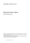
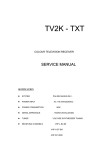
1
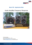
SERVICE MANUAL
Brown goods
TV SETS 14", 21" STV2248 chasis
MODELS: CTV-55A15 TXT MkII
CTV-55AF15 TXT MkII
CTV-37A15 TXT MkII
R014
5.6K
R008
5.6K
R015
5.6K
R011
5.6K
R016
5.6K
R012
5.6K
R013
5.1K
100
15
16
17
18
SAW
SW2
HT
NC
E/W
RESET
VHF
B
VHL
G
VSYNC
R
HSYNC
FB
VDDA
19
SDA
PXFM
5V
R042
20
5.1K
21
SCL
JIRSTO
VCC
GND
C005
0.22
22
23
C004
220
24
R030
6.8K 25
C028
100u/16V
26
R055 C009 0.1
27
5.6K
28
C020 4n7
JIDO
WSCF
WSCR
VDDA
VCC
MCFM
JTCK
GND
CVBS2
CVBS1
JIMS
VDDA
49
CVBSO
TXCF
D009
3.9V
10K
R049
1.2K
R034
22K
R035
33K
V-POS
IC005
24C16
R026 2.2K
41
C011
102
40
C606
4700/1KV
R036 10K
RL207
H.SYNC
39
R056
560
R050
1K
CIS-250VAC-104K
CVBS
D606
FR157
21
D607
4148
R602
R607
2.7K
220K/0.5W
3
IC601 PC817
2
4
1
C613
680/1KV
C208
10uF
C611
15n
R605
1K
R604
22K
C511 47u
26
27
C612
15n
R680
8.2M/0.5W
6
5
NC
4
C509
1000/2KV
28
R246 75
V.AMP
2
V.SYNC
3
POWER
VCC2
V AMP
BC
GND
7
1
R248
5.1K
C312
0.047
R315
10K
C333
0.01
R318
100K
R317
220K
R311
2.2K
C331
39P/500V
R312
2.2K
FB
R314
2.2K
R313
100
C305
47u/16V
R316
1.2/1W
V204
C1815
D201
5.6V
R328
2.2
C318
0.22
R249
47K
C323
0.39/400V
MUTE
R633
22K
R649
10K
C636
1000u/35V
R644
1/1W
R661
15K
C635
470/1KV
12V
H.SYNC
10
C645
470U/16V
R653
1.2K
8
ON/OFF
D640
4148
V004
C1815
135V
5V
C642
1000u/35V
1000u/25V
C651 0.1
R631
15K
HEAT
T301
BCS27-0101F
D308
3.9V
8V
IC604
7808
C015
100u/16V
R647
0.68/2W
GND
HV
IC004
7805
NC
R301
3.3K
D301
4148
130V
+180V
R338
220K
R304
560
SC
IC003
UPC574
R645
22/2W
V636
B892
XP302
R335
D306
HER155 0.68/1W
C646
1u
R636
2.2/1W
R646
22/1W
C327
22U/250V
33V
R642
100K/0.5W
C643
1000u/25V
H-DY
R319
1K/1W
C313
47u/35V
R648
15K/2W
RP601
2K
D637
6.2V
R641
150K/0.5W
L301
37UH
R327
22K/0.5W
V401
C1815
R643
5.6K
V631
C1815
V-DY
24V
D303
HER155
R415
10K
C231
470u/16V
R247
1K
MUTE7057
R632
47K/0.5W
R331
220/1W
R343
330/2W
R324
470/2W
V205
A1015
7
R336
2.2/5W
24V
R332
270/2W
20V
4
C641
x
FV
3
BC
D207
4148
HD
C319
0.1
C316
1u/160v
C302
4.7u/16V
2
R323
1K
0.5W
D307
4148
9
1
R308
15K
R306
22K
V302
2SD2499
L304
C304
3900/500V
SV
24V
T302
YDD-UU10.5
V301
C2383
C303
1000/500V
PART No : ST29TEX
8
100u/35V
R239 75 G
C212
47u/16V
C637
C681
2200/400V
9
10
D302 1N4002
11
V.SYNC IN
R321
2.2K
VCC1
C311
1000
V OUT
R334
2.2K
FLYV
IC301
TDA8174
R333
1.8K
C315
4.7u
VP
V303
C1815
R329
10k
5V(A)
D635 FR305
L801
C501
*
HEAT
VIDEO2 IN
L2
R2
BOUT
NC
V.POSITION
R326
8.2K
8V
FBEXT
REXT
GEXT
25
R214
150
J023
75
C647
1000u/16V
V602
C3807
C521
100
R240 75 B
R220
75
R613
33/2W
V603
2SD2498
R521
560
GND
Go
Bo
29
C210
1u
C211
10uF
C633
470/1KV
C610
0.1
+5V
AC110~240V 50/60HZ
30
GOUT
Icath
ROUT
31
BEXT
APR
24
D633
29
XP602
FBEXT
Ro
8V
REXT
GEXT
BEXT
V1 IN
23
C203
1u
470/1KV
HER204
R609
15K
D608
4148
R513
1.2K
D505
4148
C314
22
C634
D609
7.5V
S601
XP601
1UF
1UF
C226
C228
1UF
L1 IN
BOSD
CHR
Y/CVBSIN3
BS
20
T602
BCK-42-31EC
CIS-250VAC-224K
L501
150uH
180V
1UF
C227
1UF
C411
C412
R1 IN
L OUT
V OUT
OSD B
R OUT
GOSD
ROSD
FBOSD
32
V.SYNC
24V
CVBSIN2
XTAL2
XTAL1
XTAL3/BTUN
GND2
CVBSIN1
Vcc2
33
D632
C644
HER308 220u/160V
D634
HER204
RT601
MZ72-14RM
R606
3.3K
R057
15K
34
R212
1K
R603
22/0.5W
V601
A1015
C601
F601
3.15A/AC250V
C025
0.1
OSD R
OSD FB
C219 4700
CLPF
PIFLC2
C201
1u
36V
D605
4148
R531
2 15K
R532
*2.2/1W
C511
47u/16V
R222
270
R230 75 R
12V
8V
L003
10uH
19
35
C632
470/1KV
R615
120K/0.5W
L601
BCK UU-16
31
18
R614
68K/2W
C609
x
33
C019
2n2
17
C604
R608
5.6K/0.5W
C602
D007
1K
30
R611
120K/0.5W
YDDUF16
R059
5.6k
C022
0.47
C021
100
C608
BCK UU-16
CD293-400V-100uF-M
L602
1000/1KV
LED
339EVGW
35
C607
x
C605
x
37
34
X
D604
D601
D602
L001
10uH
38
C033
22P
16
36
D603
R601
2.2/7W
R221
270
12V
37
D208
4148
R409 2.2K
V.SYNC
R218
270
L102
7K001
VHL
D604 1N4148
36
15
R529
3.3K/0.5W
C2482
R518
330
R523
27
R512
470
C504
680
V507
C505
1015
47u/16V
R517
1K
D504
4148
R207
150
VHF
R005
100
42
14
38
C117
47u/16V
44
R006
100
OSD G
BLNK
13
39
C202
470u/16V
WOOFER.MUTE
45
43
GND1
CVBSOUT1
HOUT
Vcc1
12
C114
0.01
C113
0.22
C405
1u
0.1
40
5V
47
46
V.AMP
C215
470u/16V
C214
2.2u/16V
SLPF
VIDEO OUT
8V
BCL
AUDIO
WF.SW
20V
GND
HD
SC
SCL
V.SYNC
11
C116
*
Z101
Q3962
8
1.2K
SDA
SCL
Vcc
D507 10
5
D703
IN4001
R708 5.1K
C705
2.2u/25V
C452
47u/16V
C453
2.2u/16V
0.1
R452 4.7 C458
AUDIO
SCL
VERT
10
C406
1u
R507
15K 2
X203
41
R204
560
R044
V002
R033 C1815
48
32
9
R118
1K
C118 C119
10u 0.01
10K
R041
V003
C1815
C024 4n7
5.1K
R021
8
42
V505
V506
C1815
C317
1000u/25V
C006 33
50
C026
0.1
R018
7
GND
R511
560
8V
R-VOL
6
C109
1u
43
C IN
SW1
5
R225
75
CRT
R508
3.3K/0.5W
C506
560
X201
3.58M
VIDEO2 IN
NC
V-POS
4
R516
2 15K
R501
330
R524
27
R502
470
8V
POWER.GND
YUV
SCART2
VOL
3
C115
1u
V502
C1815
C218
0.01
VIDEO1/Y IN
13
14
SCART1
2
D008 4148
6
OSDOUT
C013
0.1
X001
4M
51
7
FAC-IN
OSDIN
SDA
FMCAP
1
RESET
52
WP
POWER
NC
44
C603 220/1KV
R040
5.1k
L001
10uH
NC
45
PIFLC1 X1/VAMP/CHROUT
R037
3.3K
53
C217
0.1
46
EXTAUDIO
12K
47
AGC
12
R010
1k
C003
0.1
33K VT
C001
0.1
R515
3.3K/0.5W
XS201
RO
BO
R217
1K
X202
4.43M
4 GND SDA 5
11
J
R020
5.6K
22k
48
IC101
STV2248
Vcc
10
R007
33V
R001
A0
9
J
XP005
KEY
22K
R002
C216
0.1
R234
1K
49
INTCVBSOUT
54
C027
0.1
50
C221
0.01
C222
0.01
R233
18K
C224
0.22
VccIF
R039
R022
22K
10K
8
10K
XP005
V001
C1815
51
R211
1K
R231
X
BCL/SAF
C012
150
55
52
R514
330
V501
R232
82K
AM/FMOUT
VT
S-BYLED
56
53
R525
27
R509
470
C507
680
V OUT
R403 R404
10K 10K
R235
56K
R227
5.1K
R215
15K
C206
0.01
54
V504
C2482
C2482
5V(A)
MUTE
NC
55
VIDEO
OUT
XP702
GND IF
AV
KEY-IN
56
C402
1u
R208 75
R202
560
WOOFER
IFPLL
RESET
SDA
TVR
C207
1u
5V
10K
C213
4700
CRT BOARD
V503
C1815
GO
R307
1K
LFB/SSC
IRIN
C205
47u/16V
R201
75
V203
1815
8V
R405
10K
C702
22u/25V
D206
4148
R226
100
R229
100
L2
R406
10K
R701
J
C701
0.22
R236
8.2K
C103
0.1
C204
10u 16V
C709
0.22
XP403
D205
4148
RO
R241
75
AV OUT
C403
1u
R401
560
R242
75
R025
100K
R700B
6.2K Z102
Q9350
C104
0.1
R711
1
R402
560
LO
R213
75
XP701
5V(A)
MUTE
20V
AMP LO
AMP RO
LO
RO
L2
R1
GND
NC
IF
D101
5.1V
R701B
3.9K
SCL
R023
10K
R024
6.8K
Vcc
R702B
2.2K
C007 33
5
R004
SCL
R703B
1K
R114
100
R485 100K
7
SDA
SW6
P+
R464
220
C707
10n
D702
1N4001
R702
10K
TUNERAGCOUT
3
6
OSD FB
SW5
P-
C455
4.7u/16V
SIFIN1
2
R019
100K
OSD R
SW4
V+
C454
1u
R413
100K
R414
47K
R038
1
RE
HS0038
GND
4
OSD G
R704B
9.1K
R203
33
RESET
OSD B
SW3
V-
1K
C408
47u/16V
R028
OUT
ICMUTE
XP002 PIN2
C441
1000u/25V
SW2
MENU
R705B
15K
11
C111
47u
R451
1K
C443
2.2u/16V
IC001 ST92195
VCC
BLNK
10
R463
5.6K
R461
R103
10K
R053
10k
ON/OFF
9
2
R448
10K
PIFIN1
8
5.1K
R106
33K
C014
0.1
5 4
C445
4.7u/16V
AGCPIFCAP
7
C108
0.1
R107
R051
10
NC
NC
6
SW1
OK
7
R238
75
C710 1000u/25V
C711
1u
V701
C1815
KEY
R102 10K
R054
100
5V
2
D401
3.6V
3 A2
5
VCC
BL
BH
4
C102
0.1
AGC
D441
4148
7
5 4
8V
C107
0.1
C112
47u/16V
C461
4700
15
C449
0.1
VHF-I
VHF-II
14
R710
22K
C703
10u/25V
V702
C1815
10K
Vcc D
13
100K
R712
GND D
12
6
Vref IF
11
3
AGCSIFCAP
10
IC403
TDA1905
9
10
11
12
13
14
15
16
R462
4.7
R454
220
8V
9
6
8
C448
0.1
C442
47u/16V
C444
1u
3
TDA1905
2 A1
3
9
10
11
12
13
14
15
16
16
1
2
BU
VT
AGC
1
17
TVL
8
TUNER
VT
C446
0.1
18
R706
100K
R707
100K
1
C456
0.1
AUDIOOUT
19
R705
R704
0.22
SIFIN2
2.7K
R424
R423
5.6K
20
R453
5.6K
IC402
8
C424
10n
0.1
C423 22n
21
C459
0.1
1
R411 1K
1K
7
TO AMP RO
TO AMP LO
8V
SDA
C401
10u
SCL
6
5
22
TVL
4
23
C462
4700
TDA7439
R2
3
R412
2
100
R416
1
5.6K
24
C422
R421
25
0.1
C421 0.1
22n
C417 0.1
2.7K
26
IC401
TVR
27
L1
28
C418
5600
C415 10n
R422
C414
5600
29
C416
C413
30
D451
4148
V2
R2
R237
75
C706
1000u/25V
D701 5.1K
5.1K
C457
470u/25V
C425
C426
4.7u/16V 4.7u/16V
4
WOOFER
BOARD
C447
470u/25V
MAIN BOARD
2
1
SCH21ST9JL
R455
R
SCART
TDA2030
IC701
5.1k
3
R456
XP401
NC
AV IN
XP402
L
PIFIN2
SPEAK
SCHEMATIC DIAGRAM
1.RESISTANCE VALUES INΩ1/4W UNLESS OTHERWISE SPECIFIED.
2.CAPACITANCE VALUES IN uF50V IF LESS THAN 1 AND
IN pF50V IF MORE THAN 1 UNLESS OTHERWISE SPECIFIED.
3.CIRCUITRY ARE SUBJECT TO CHANGE WITHOUT NOTICE FOR
FUTHER IMPROVEMENT.
C321
470/2KV
C332
*1n5/1.6KV
R341
8.2K
C322
103/1.6KV
C326
0.47/630V
D304
FR305
C309
47n
TABLE OF CONTENTS
S/N
1
2
3
4
5
6
TOPIC
Page #
INTRODUCTION
1.1Definitions , Acronyms and abbreviations
1.2References
SPECIFICATION SUMMARY
2.1Hardware
2.2Tuning
2.3Control
2.4OSD(On Screen Display)
2.5Sound
2.6Peri-TV
2.7Memory
2.8Power ON
2.9Standby
2.10Adjustments
BASIC HARDWARE DESCRIPTION
3.1 BASIC HARDWARE SPECIFICATION
3.2 MICROCONTROLLER ST92195
3.4 MULTI STANDARD TV PROCESSOR STV223X/4X
3.5 MULTI STANDARD SOUND DEMODULATOR STV8203A
3.6 SOUND PROCESSOR TDA7449/TDA7439
3.7 E_W CORRECTION PROCESSOR STV9306
3.8 REMOTE CONTROL TRANSMITTER M3004LAB1
4
4
4
5
5
5
5
5
6
6
7
7
7
7
9
9
9
9
9
9
10
10
ST92195 PIN DESCRIPTION
4.1 RESET
4.2 R, G, B BLANK
4.3 XTAL
4.4. BAND SWITCHING OUTPUT
4.5 AV STATUS
4.6 KEYBOARD INPUT
4.7 POWER MODE CONTROL
4.8 I2C LINES
4.9 SAW SWITCHING
FUNCTIONAL DESCRIPTION
5.1Interface Description
5.2Tuning
5.3Sound System
USER INTERFACE
6.1Direct Controlled Function
6.2Menu Controlled Function
11
13
13
13
13
13
13
13
14
14
15
15
19
20
21
21
26
7
6.3Service Controlled Function
Appendix A :IR Commands
35
40
1. INTRODUCTION
CTV5 is a Voltage Synthesis Tuning and control system for multi-standard TV receivers with
on-screen-display (OSD) for all relevent control functions. The system is based on I2C bus
controlled video processing IC STV223X/4X which also controls mono sound. The Nicam and
Zweiton demodulation is done using IC STV8203. It is also possible to do picture geometry
correction using IC STV9306.
The user interface is menu based control system with P+ ,P- ,V+ , V- , MENU OK and TV/AV
keys on Remote / local keyboard . Hence any menu related function could be accessed using
these six keys.
Teletext is done by the microcontroller on-chip teletext module.
1.1 Definitions , acronyms and abbreviations
ADC
AFC
AV
DAC
I2 C
IDENT
FE
LS
MS
NV-memory
OSD
PP
VST
Video proc.
PIF
SIF
NICAM
Analogue to Digital Converter
Automatic Frequency Control
Audio Video peripheral TV signal source
Digital to Analogue Converter
Inter IC bus, 2-wire, bidirectional multi-master bus
Horizontal coincidence signal, transmitter IDENTification
Front End
Loud Speaker
Multi Standard
Non-Volatile memory
On Screen Display
Personal Preference
Voltage Synthesis Tuning
STV2238, integrated I2C bus controlled PAL/SECAM/NTSC TV-processor
Picture Intermediate Frequency.
Sound Intermediate Frequency.
Near Instantaneous Companded Audio Multiplex
1.2 References
ST92195 Datasheets
STV223X/4X Datasheet
STV8203A Datasheet
TDA7439/7449 Datasheet
STV9306 Datasheet
2. SPECIFICATION SUMMARY
2.1 Hardware
The microcontroller has 24/32/48/64K ROM, 256 bytes RAM, 0/256/512 bytes Aux RAM, bitlevel I2C, on-chip 0/1/7 page teletext, OSD.
2.2 Tuning
|
|
|
|
|
|
|
|
|
Voltage synthesis tuning system via 14-bits PWM-DAC.
Automatic search tuning based on AFC and IDENT.
Tuning in VST system in 3 bands (VHF-L,VHF-H,UHF).
Fine up and down tuning.
Auto Program function to find and store all transmitters.
Automatic PAL/SECAM/NTSC recognition.
Suitable for negative and positive modulation.
Programme-Up/Down keys to select 99 programmes.
Silent tuning.
2.3 Control
|
|
8 Local Keys (P+, P- , V+ , V- , Menu , OK, TV/AV ,Service)
Max 32 Remote Keys
2.4 OSD ( On Screen Display )
MENU CONTROL
Picture Menu
Brightness (64 Steps)
Contrast (64 Steps)
Colour (64 Steps)
Sharpness (16 Steps)
Tint ( 64 Steps , Only for NTSC)
Sound Menu
Bass (64 Steps)
Treble (64 Steps)
Balance (16 Steps)
Volume (64 Steps)
Install Menu
Auto Tune
Manual Tune
Fine Tune (+ - 64 Steps from centre frequency )
Store .
Setup Menu
The Setup Menu contains 4 submenus:
Timer
Time (Hour = 0 ... 23 , Minute = 0 ... 59)
On Timer (Hour = 0 ... 23 , Minute = 0 ... 59)
Off Timer (Hour = 0 ... 23 , Minute = 0 ... 59)
On Timer Pr ( 1 ... 99 )
Organize
Program ( 1 ... 99)
Label (4 digit with each program , A to Z , + ,-, SPACE , 0 to 9)
Picture ( AUTO / PAL , SECAM , NTSC1, NTSC2)
RF Std ( BG , DK , I , LL’, MN ) for Europe
Skip ( Yes / No )
Function
Blue back (Yes/No)
Children Lock (Yes/no)
Language
English
French
German
Italian
Spanish
Portuguese
Greek
Dutch
Danish
Swedish
Finnish.
Norwegian.
2.5 SOUND :
| Volume control in 64 steps .
| Stereo Sound .
| Multistandard Nicam and Zweiton demodulation.
| Automatic mute during program change.
| Fully suitable for FE -sound output on AV1 connector.
2.6 PERI-TV :
| AV has FE audio /video input / Output , RGB inputs (Full SCART)
| Auto SCART level detection
2.7 MEMORY :
| Storage of last Sound and Picture settings.
| Storage of last Channel, Power status.
| Storage of Tuning information of the 99 programs.
| Storage of Label of 99 programs (Each of 4 characters)
| Storage of Service settings .
| Storage of Alarm settings.
| Storage of Nicam / Zweiton standard of 99 programs.
| Storage of Child-Lock value.
| Storage of Customer character LOGO.
2.8 POWER ON :
| If the TV is in ON state before the mains switch is made OFF , at power-on-reset via mains
switch ,the TV goes in to POWER ON mode . If the Set is in Standby before the mains switch is
made OFF, at power-on-reset via mains switch ,the TV goes in to Standby mode.
| The program provides a fixed delay of 1 second and screen blanking of about 500 msec to
allow SMPS to stabilise.
| After power-on-reset of microcontroller and first time switching of the set, the system tunes
to program 1 and recalls analog picture and sound controls from the EEPROM.
| If the set is in standby , the TV set comes out of standby using Digit keys , P+ and P- keys.
2.9 Standby :
|
Sleep timer selection of in steps of 10 minutes till a maximum of 120 minutes.
Automatic switching to standby mode when there is no valid signal for 5 minutes.
2.10 Adjustments
Initialize EEPROM (ROM default values programmed into EEPROM).
Through Service menu-1 the following parameters could be adjusted:
| Adjust Red Gain
| Adjust Green Gain
| Adjust Blue Gain
| Adjust DC Red
| Adjust DC Green
| Adjust DC Blue
| Adjust APR threshold
| Input the customer character LOGO.
| Adjust Red cutoff.
| Adjust Green cutoff
Through Service menu-2 the following parameters can be adjusted:
| Adjust Tuner AGC
| Adjust H-position
| Adjust V-position
| Adjust V-amplitude
| Adjust Sub_tint
| Adjust Sub_brightness
| VCO Coarse.
| VCO Fine.
| VCO Coarse L’
| VCO fine L’
Through Service menu-3 (STV9306, if there is no STV9306 then this menu is not displayed):
| Adjust V-Amplitude (50Hz/60Hz).
| Adjust V-Position
| Adjust C-Correction
| Adjust S-Correction
| Adjust H-Amplitude
| Adjust EW-Amplitude
| Adjust EW-Trap
| Adjust EW-Shape
Through Service menu-4 (Design menu) following parameters are adjusted
| Adjust Tuner AGC gain.
| Adjust Option1
| Adjust Option2
| Adjust Option3
| Adjust Option4
| Adjust Option5
| Adjust Sttext
| Adjust HPOS_OSD
| Adjust VPOS_OSD
| Adjust HPOS_OSD_Teletext
| Adjust VPOS_OSD_Teletext
3. BASIC HARDWARE DESCRIPTION
3.1 Basic Hardware Specification
The CTV5 system has following components :
| ST92195
MCU + OSD + TXT controller with CTV5 software inside.
| 24C08
1K byte Non Volatile memory (EEPROM).
| STV2238/46/48
Bus Controlled Multi-standard TV Processor.
| STV8203A
Bus controlled Multistandard TV Sound Demodulator.
| TDA7439/7449
Bus controlled Audio processer.
| STV9306
Bus Controlled Vertical deflection system with E-W correction output
circuit.
| M3004LAB
Remote Controlled Transmitter.
| Voltage Synthesis Tuner.
Communication between microcontroller (master) and all I2C bus controlled devices (slaves) is
done using a two-wire bidirectional I2C bus.
3.2 Microcontroller ST92195
Microcontroller + OSD +Teletext decoder + VPS/PDC/WSS decoder are embedded in one chip.
For the details of microcontroller please refer to the ST92195 data sheet.
3.3 Non Volatile Memory 24C08
The 24C08 is a 8K-bit 5V electrically erasable programmable read only memory (EEPROM),
organised as four pages of each 256 by 8 bits. Data and instructions are transferred via the I2Cbus. Minimum programming time is 10 ms. Data retention is at least 10 years, independent of
the power-on/off status. The number of erase/write cycles per address is greater than 105 for
24C08B.
3.4 Multi Standard TV Processor STV223X/4X
STV223X/4X is a fully bus controlled IC for TV including PIF, SIF , Luminance , Chrominance
and deflection processing. It is a bus controlled PAL / SECAM / NTSC single chip TV
Processor.
For details of STV223X/4X features please refer to the STV223X/4X datasheet.
3.5 Multi Standard Sound Demodulator STV8203A
The STV8203A provides all the necessary circuitry for demodulation of all Nicam and German
Stereo audio transmission.
For details of STV8203A features please refer to the STV8203A datasheet
3.6 Sound Processor TDA7439/TDA7449
The TDA7439/7449 is a volume tone (bass and treble) balance(Left/Right) processor for quality
audio.
TDA7449 provide 2 stereo inputs while TDA74439 provide 4 inputs.
For details of TDA7439/7449 features please refer to the TDA7439/7449 datasheet
3.7 E-W Correction processor STV9306
The STV9306 is a fully bus controlled IC for vertical deflection and designed for use in 110° ,
4:3 or 16:9 CRT application. It integrates both vertical deflection and E-W correction circuit
necessary for design of 110° chassis
3.7 Remote Control Transmitter M3004LAB1
See Appendix -A . For details see M3004LAB1 datasheet.
IR IN
RESET
NC
MUTE
56 KB INPUT
55 NC
1
2
3
54 VS OUT
53 LED1
52 LED2
4
NC 5
ON/OFF 6
DESIGN 7
SCART1 8
51
XTAL
SCART2 9
AV SEL 10
S0 11
S1 12
NC 13
NC 14
ST9219
50 XTAL
49 VOL PWM
48
47
Vlin PWM
46
45
SAW-SW2
NC
44
SAW-SW1
43
NC
G 16
41
BSW2
BSW1
VSYNC
R 17
FB 18
40
HSYNC
B 15
42
39 AVDD1
38 PXFM
SDA 19
SCL 20
37 JTRST0
36 GND
VDD 21
JTDO 22
WSCF 23
WSCR
24
AVDD3
25
TEST0
26
MCFM
27
28
JTCK
35 AGND
34 TELETEXT
33 WSS
32 JTMS
31 AVDD2
30
CVBS0
29 TXCF
4. ST92195 PIN DESCRIPTION
Pin
1
2
3
4
5
6
Pin Name
P2.0
RESET
P0.7
P0.6
P0.5
P0.4
Signal Name
IRIN
RESET
NC
MUTE
NC
ON/OFF
I/O
I
I
I/O
O
I/O
O
Function
IR Input
Hardware Reset
Not Used
MUTE OUTPUT PIN
Not Used
STANDBY OUTPUT
7
8
9
10
11
12
13
14
15
16
17
18
19
20
21
22
23
24
25
26
27
28
29
30
31
32
33
34
35
36
37
38
39
40
41
42
43
44
45
46
47
48
49
50
51
52
53
54
55
56
P0.3
P0.2
P0.1
P0.0
P3.7
P3.6
P3.5
P3.4
B
G
R
BLANK
P5.1
P5.0
VDD
JTDO
WSCF
WSCR
AVDD3
TEST0
MCFM
JTCK
TXCF
CVBSO
AVDD2
JTMS
CVBS2
CVBS1
AGND
GND
JTRST0
PXFM
AVDD1
HSYNC
VSYNC
P4.0
P4.1
P4.2
P4.3
P4.4
P4.5
P4.6
P4.7
XTAL
XTAL
P2.5
P2.4
P2.3
P2.2
P2.1
DESIGN
SCART1
SCART2
AV SEL
S0
S1
NC
NC
B
G
R
BLANK
SDA
SCL
VDD
JTDO
WSCF
WSCR
AVDD3
TEST0
MCFM
JTCK
TXCF
CVBSO
AVDD2
JTMS
CVBS2
CVBS1
AGND
GND
JTRST0
PXFM
AVDD1
HSYNC
VSYNC
BSW1
BSW2
SAW_SW1
NC
SAW_SW2
NC
Vlin PWM
VOL PWM
XTAL
XTAL
LED2
LED1
VS
NC
KB INPUT
I
I
I
O
O
O
I/O
I/O
O
O
O
O
I/O
O
I
I
I
I
O
O
O
I/O
O
I/O
O
O
O
O
O
I/O
I
Service menu control
Identify scart entering
Identify scart entering
AV SELECTION
AV/TV
AV/TV
Not Connected
Not Connected
OSD Blue colour Signal
OSD Green colour Signal
OSD Red colour Signal
OSD Blanking Output
I2C data line
I2C clock line
+5 V Digital Supply
Test Pin
Analog Pin For VPS / WPP
Analog Pin For VPS / WPP
+5V Analog VDD For PLL
Test Pin
Analog Pin for display pixel
Test Pin
Analog pin for VPS /WSS
Test Pin
Analog Power supply
Test Pin
CVBS In for VPS / WSS
CVBS In for Teletext Slicer
Analog Ground
Digital Ground
Test Pin
Analog Pin for display pixel
Analog Power Supply
Horizontal Sync Input
Vertical Sync Input
Band Switch 1
Band Switch 2
SAW Filter Switch 1
Not Connected
SAW Filter Switch 2
Not Connected
V-linearity PWM OUTPUT
VOL PWM OUTPUT
Clock Oscillator
Clock Oscillator
LED DRIVER
LED DRIVER
VST Voltage Ouput
Not Connected
KEY INPUT
4.1 RESET :
Reset is active low Input. The ST9+ is initialized by the Reset Signal. With the deactivation of
RESET , program execution begins from program memory locations 00h and 01h.
4.2 R,G,B,BLANK :
Red / Green / Blue / Fast Blanking. On Screen Display DAC outputs.
4.3 XTAL :
These pins connect a parallel resonant crystal of 4 MHz.
4.4. BAND SWITCHING OUTPUTS :
BSW1
BSW2
0
0
0
1
1
0
1
1
SELECTED BAND
NOT USED
VHF_L
VHF_H
UHF
4.5 AV STATUS :
4.5.1 SCART 1 / SCART 2 (pin 8 & pin 9)
SCART_SW pin of the microcontroller monitors the status of the AV SCART Connector. When
the signal at this pin goes from low to high , the set will automatically switch to AV and when it
goes from high to low the set will automatically switch to the previous source.
4.5.2 AV SELECTION (pin 10)
10 pin status
0
1
AV MODE
AV1 / RGB
AV2 / S-VHS
4.5.3 TV / AV SELECTION (11 pin / 12 pin )
S0-11 pin
0
1
0
1
S1-12 pin
0
0
1
1
TV / AV MODE
TV
AV1/RGB
AV2
S-VHS
4.6 KEYBOARD INPUT :
It is ADC input of the micro. The Voltage at the select ADC Pin of the micro is monitored and
depending on the voltage value at this pin it is decided as to which key is pressed.
KEY IN (Pin 56)
KEY PRESSED
0.3~ 0.7V
Volume – (120 ohm)
0.8 ~ 1.2V
Volume +(270 ohm)
1.3 ~ 1.7V
Program-(470 ohm)
1.8 ~ 2.2V
Program+(680 ohm)
2.3 ~ 2.7V
MENU(1 Kohm)
2.8 ~ 3.2V
OK(1.5 Kohm)
3.3 ~ 3.7V
AV/TV(2.2 Kohm)
3.8 ~ 4.2V
Analog(3.3 Kohm)
4.7 Power mode control :
The STD-BY Output specifies if the set is in Stanbby mode or operating mode.
STD-BY
Mode
(Pin 6)
0
Standby
1
Operating
4.8 I2C Lines :
Pins 19 (SDA) and 20 (SCL) of the MCU are the I2C Lines. The I2C bus is a 2 wire bidirectional
bus. The CTV5 has an on-chip bit level I2C interface . This means the hardware takes the bus
arbitration , the reception and transmission of data bits and generation of START and STOP
condition. The software must handle the bits (i.e save a received bit and prepare the bits which
must be transmitted. )
CTV5 supports 1K bytes EEPROM (ST24C08) used for storage of analog controls , Service
settings, Alarm Settings, tuning data for 99 pre-selected programmes and label for each of them.
The I2C address of the EEPROM is shown in the next chapter.
The Video processor STV223X/4X is controlled via I2C on address 8A hex.
4.9 Design pin 7:
It is available to enter SERVICE MENU when it is high for the voltage at pin 7 of MCU. It is
forbidden to enter the SERVICE MENU when the voltage level is low at pin 7 of MCU.
5. FUNCTIONAL DESCRIPTION
This section describes all functions and hardware requirement of CTV5. Overall control of the
system is done by the microcontroller which :
| Decodes the data from the Remote controller.
| Decides on which local key is pressed
| Controls the On Screen Display.
| Exchanges information via I2C bus.
| Selects the proper tuner band and generates the 14 bit data for the internal Voltage
synthesised tuning DAC.
| Selects proper IF and Sound demodulator.
| Selects proper Nicam /Zweiton decoder/demodulator .
| Controls analog picture settings and picture geometry.
| Switches between internal and external audio and video signals.
5.1 Interface Description :
5.1.1 Remote Control Handset :
A remote control handset compatible with CTV5 can be designed using M3004LAB1.
5.1.2 Remote control decoding :
The infra red remote control pulses are modulated at a frequency of 38 Khz .The remote control
signal (active high) from the IR receiver is fed to the external interrrupt input IR-INPUT (pin 1)
of the microcontroller.
The following table lists all remote commands to which standard remote control responds
to.
Name
0
1
2
3
4
5
6
7
8
9
TENS(-)
Review
Standby
Mute
Sleep
PP(VSM)
Audio PP
Analog
Recall
Menu
Code
0x10
0x11
0x12
0x13
0x14
0x15
0x16
0x1e
0x18
0x19
0x1a
0x28
0x20
0x36
0x09
0x2e
0x2d
0x33
0x2a
0x2b
TV Mode
0
1
2
3
4
5
6
7
8
9
TENS
Channel review
Power on/off
Mute/unmute
Sleep
Vedio PP
Audio PP
Audio adjust
Status recall
Menu switch
Menu Mode
0
1
2
3
4
5
6
7
8
9
Power on/off
Mute/unmute
Channel move
P+
P-
0x1c
0x1b
Channel+
Channel-
V+
V-
0x24
0x25
Volume+
Volume-
Menu item up
Menu item
down
Increase value
Decrease value
AV
0x29
Sourse changed
Channel delete
Service
NICAM
OK
0x05
0x35
0x2c
Service in
NICAM
-
Txt
Index
Size
Mix
0x31
0x01
0x0e
0x0c
Enter txt
Sub menu
enter
-
Service Mode
A
Power on/off
Line gain adjust
Service exit
TXT Mode
0
1
2
3
4
5
6
7
8
9
Reveal
Power on/off
Sub brightness
GREEN key
CYAN key
YELLOW key
Auto center
VCO
Item up
Item down
Run_time
_mode _choice
Page plus
Page minus
Value+
ValueAuto adjust
VCO
Menu switch
-
RED key
Exit txt
Index
Size
Mix
Cancel
Stop
Reveal
Subcode
0x0b
0x06
0x0a
0x04
Cancel
Stop
Reveal
Subcode
5.1.3 Non Volatile Memory :
The CTV5 tuning and sound system requires 1KBytes non volatile memory (24C08). With such
a memory the system is able to stores tuning information and label of the 99 preselected
programs along with the last picture /sound control settings, Service and Alarm Settings.
The following is EEPROM Address map defined in EEPROM.h:
Signature Byte (address = 0 & 1023):
Value = 0xDC
Service Signature Byte (address = 1 & 1022):
Value of service in= 0x66, Value of service out= 0x99.
Power related byte (address =3):
EEPROM_TV_OPTIONS
EEPROM_STANDARD_SELECTION
EEPROM_P_PP
EEPROM_S_PP
EEPROM_LAST_CHANNEL
EEPROM_LANGUAGE
EEPROM_POWER_STATUS
START VIDEO Byte(address = 10):
EEPROM_BRIGHTNESS
EEPROM_CONTRAST
EEPROM_COLOR
EEPROM_SHARPNESS
EEPROM_TINT
EEPROM_VOLUME
EEPROM_BALANCE
EEPROM_BASS
EEPROM_TREBLE
Service RGB Byte (address = 19)
EEPROM_RED_GAIN
EEPROM_GREEN_GAIN
EEPROM_BLUE_GAIN
EEPROM_DC_RED
EEPROM_DC_GREEN
EEPROM_DC_BLUE
EEPROM_APR_THRESHOLD
EEPROM_RED_CUT_OFF
EEPROM_GREEN_CUT_OFF
Service Byte (address = 28)
EEPROM_AGC
EEPROM_HORIZONTAL_SHIFT
EEPROM_VERTICAL_POSITION
EEPROM_VERTICAL_POSITION_60
EEPROM_VERTICAL_AMPLITUDE
EEPROM_VERTICAL_AMPLITUDE_60
EEPROM_BRIGHT_MAX
EEPROM_BRIGHT_MIN
EEPROM_SUB_TINT
EEPROM_PLL1
EEPROM_PLL0
EEPROM_PLL1_L1
EEPROM_PLL0_L1
Design Byte (address = 41)
EEPROM_AGC_GAIN_ADJUST
EEPROM_MISC1
EEPROM_MISC2
EEPROM_MISC3
EEPROM_MISC4
EEPROM_MISC5
EEPROM_MISC6
EEPROM_HPOS_OSD
EEPROM_VPOS_OSD
16 EEPROM_HPOS_OSD_TELETEXT
EEPROM_VPOS_OSD_TELETEXT
Service STV9306 Byte (address = 52)
EEPROM_V_SAW50
EEPROM_V_SAW60
EEPROM_V_SH50
EEPROM_V_SH60
EEPROM_V_SC
EEPROM_V_CC
EEPROM_EW_VDC
EEPROM_EW_AMP
EEPROM_EW_SHAPE
EEPROM_EW_TRAP
EEPROM_S_BRIGHTNESS(address =62)
EEPROM_S_COLOR(address =63)
EEPROM_S_CONTRAST(address =64)
Alarm Byte (address = 65):
EEPROM_ALARM_SET
EEPROM_ALARM_CHANNEL
EEPROM_ALARM_ON_HOUR
EEPROM_ALARM_ON_MINUTE
EEPROM_ALARM_OFF_HOUR
EEPROM_ALARM_OFF_MINUTE
Child Lock Byte (address = 71):
EEPROM_CHILDKEY_CODE1
EEPROM_CHILDKEY_CODE2
EEPROM_CHILDKEY_CODE3
EEPROM_RUN_TIME_CHOICE_TABLE (address = 74)
LOGO data : (start address = 80 or 0x50 )
Offset
bit 7
bit 6
bit 5
bit 4
bit 3
bit 2
bit 1
0
Lenght should < MAX_LOGO LENGTH =12 (ASCII char)
1-12
LOGO characters (ASCII char)
bit 0
Tuning Data : (Offset=96,Total = 99 * 3 Bytes)
bit 7
bit 6
bit 5
bit 4
bit 3
bit 2
bit 1
bit 0
0
Band
Band
Tuning Value bit 13 .... 8
1
Tuning Value bit 7 ..... 0
2
Chroma Standard
Skip
Super
RF Standard
sense*
* Only for the SUPER TUNER is used.
Name /Label Data : (Total = 99 * 4 Bytes )
Offset
bit 7
bit 6
bit 5
bit 4
0
X
X
1
X
X
2
X
X
3
X
X
Fine Tune data : (Total = 99 *1 Bytes )
Offset
bit 7
bit 6
bit 5
0
X
bit 3
bit 2
bit 1
Character 1 bits 5 ...... 0
Character 2 bits 5 ...... 0
Character 3 bits 5 ...... 0
Character 4 bits 5 ...... 0
bit 4
bit 3
bit 2
Fine tune bits 6 ..... 0
Nicam/Zweiton data : (Total = 99 *1 Bytes )
Offset
bit 7
bit 6
bit 5
bit 4
Dual2
Mono
X
X
X
bit 3
X
bit 2
X
bit 0
bit 1
bit 0
bit 1
X
bit 0
X
5.2 Tuning :
This section describes the tuning algorithm , the corresponding OSD is described in the user
interface section.
5.2.1 Automatic tuning based on Voltage Synthesis Principle :
CTV5 provides an automatic tuning system in 3 different tuning bands . The search tuning
function requires a IDENT signal and AFC window status , which is read via I2C from
STV223X/4X. AFC status could be in one out of the following 5 states:
| F pll - Fo < -300 Khz
| -300KHz < F pll - Fo < -60 KHz
| -60 KHz < F pll - Fo < +60 KHz
| +60 KHz < F pll - Fo < +300 Khz
| +300 KHz <F pll - Fo
If the search is activated while the TV is tuned to a station (IDENT available ) , CTV5 will first
try to escape from it. The tuning voltage will be increased until ident fails. After this the search
for the new transmitter can start.
The tuning voltage is increased till the transmitter is found. When the tuning reaches the top of
the band , it will change to the next higher band. The band is tuned in the following order :
VHF-L
VHF-H
UHF
During the search CTV5 continuosly scans its IDENT and AFC status, read via I2C bus. Good
performance hence relies completely on the behaviour of these two signals.
5.2.2 Automatic Following :
Once the system is tuned via automatic tuning , the signal will stay locked by means of
automatic following (Using digital AFC ). This transmitter following will continue as long as the
transmitter identification signal stays present.
Once fine tune is activated the automatic following is disabled.
If Compilation option of FINE_TUNE_STATUS is selected ,the AFC status is stored with the
individual program. If the fine tune value of a particular program is not zero, the AFC following
for that program is disabled.
5.3 Sound System :
Presently the mono sound is received from STV223X/4X. This is fed as Mono I/P to STV8203A.
In case the Nicam or Zweiton signal is not detected it switches to Mono input.
If in auto tuning “France” is selected , AM sound system will be selected . Also in Organize
menu if RF std. is selected as LL’ , AM sound system will be selected.
By pressing “NICAM” key on remote in normal mode , it is possible to change the language,
if the standard is NICAM DUAL or Zweiton DUAL.
6. USER INTERFACE :
6.1 Direct Controlled Functions :
6.1.1 Digit Entry :
Programs 1 to 99 can be directly accessed through keys 0 to 9 on remote. but for programs
10~99, it can be accessed by pressing key -/-- first, Say if you want to access program 23 , press
key -/-- to see -- on the screen , then press 2 and within 3 seconds of pressing 2 , press key 3. If
key 3 is not pressed within 3 seconds the program accessed is program number 2. Digit entry is
not possible in AV mode.
6.1.2 Program + / - key :
The P+/P- keys can be used to select 1 ...99 unskipped programs. The program which is skipped
can’t be accesed through program UP / DOWN keys.
6.1.3 The status and time display:
When STATUS key is pressed for the first time ,the source status along with time appears on
screen for 5 seconds .
If the Nicam is detected the OSD will be as following:
When STATUS key is pressed for the second time, the time will always dispalyed as following:
When STATUS key is pressed for the third time, all the OSD will hide.
6.1.4 Image ambiance Key (PICTURE_PP):
The TV picture can be adapted to suit the current lighting conditions. Press Successively to
select the desired settings.
Soft
Dynamic
Favourite
Standard
STANDARD, SOFT and DYNAMIC are preset values of Brightness,Contrast and Colour,
whereas FAVOURITE is the last analog setting that the user had set.
6.1.5 Sound ambiance Key (SOUND_PP) :
The TV picture can be adapted to suit the current conditions. Press Successively to select the
desired settings.
Music
News
Favourite
Standard
STANDARD, SOFT and DYNAMIC are preset values of BASS TREBLE and BALANCE,
whereas FAVOURITE is the last analog setting that the user had set.
6.1.6MUTE :
Sound can be switched OFF immediately with MUTE command. A second reception of this
command returns the sound to previous level.
Sound mute is cancelled by a Volume + /- command.
When MUTE is activated the display appears as follows:
6.1.7 Volume Control :
Volume can be controlled using V+/V- keys. The Volume string and bar are displayed at the
bottom of the screen.
6.1.8 ANALOG SETTING
Press key “ANALOG” you will have the right to choose the picture and sound settings as follow:
VOLUMEÆBRIGHTÆ CONTRAST Æ COLOR ÆSHARPNESSÆTINT(NTSC
only)ÆBASSÆTREBLEÆBALANCE
6.1.9 AV1/ AV2 , SVHS , RGB Selection :
The AV1 input, AV2 input, SVHS and RGB mode (External inputs) can be selected by pressing
the AV key. All those modes can be enabled or disabled in the servise mode one by one.
You can individually define whether or not to include AV1,AV2 , SVHS and RGB mode.
If all these inputs are defined then by successively pressing AV key the source changes in the
following sequence :
AV1
AV2
SVHS Mode
RGB Mode
RF
In case SVHS is not defined then the sequence will be as follows :
AV1
AV2
RGB Mode
RF
In case of the AV2 disabled, the AV1 will displaying “AV” when it is selected.
Inside the menu, AV command is not functional.
In RF mode the PLL1 time constant is set as “Auto” and in other modes (AV1,AV2, SVHS,
RGB) it is set as “short time constant”.
6.1.10 Standby :
Pressing the standby key switch will put the set in Standby mode if it is ON.
If the Set is in Standby, Pressing Standby key , P+/P- Key or any digit key will put the set in ON
condition.
The last power status is stored in the EEPROM. If the set was in standby before mains switch
was put OFF , by again turning ON the mains switch the set will go to standby. If the set was in
ON condition before main switch was put OFF , by turning ON the mains switch the set will go
in ON condition with the most recent program, Sound and picture settings recalled from
EEPROM.
6.1.11 Sleep Timer :
The set will switch OFF if the sleep timer expires . The Sleep timer can be set in steps of 10
minutes with a maximum of 120 minutes.
6.1.12 Auto ShutOff Timer :
When no Front end IDENT (from RF) is detected for 5 minutes ,the set will switch to standby
automatically .
6.1.13 NICAM Status change and display :
If not in Teletext mode , pressing the “I/II” key on remote displays the Nicam/Zweiton / Mono
Standard on third line ( BG, DK, I , LL1) and stereo mode in the next line ( Dual1, Dual2).
If the “mono” displayed in Red color, that means the Nicam/Zweiton is available and the user
have force the sound to mono mode. However, if the “mono” in Green color, maybe the
Nicam/Zweiton is not available now.
6.2 Menu Controlled Function :
6.2.1 General Menu Operations :
To minimize the number of keys on remote , the less frequent used functions are only accessible
via menus. These menus are controlled by following keys.
w MENU button select the diffirent menus.It is also used to return from a submenu to menu.
w P+ and P- keys for selecting items in a particular menu.
w V+ and V- keys for changing the value of selected item .
w OK key to enter a Sub menu.
6.2.2
PICTURE MENU :
If press the Menu key for the first time, we can get Picture menu.
The Picture menu has following items :
a) Brightness (64 Steps )
b) Contrast (64 Steps )
c) Colour (64 Steps )
d) Sharpness (16 Steps )
e) TINT ( Only for NTSC , 64 Steps )
These items could be selected through P+/P-keys. Item value can be modified by V+/V-keys.
The graphic and numeric display of the control level of selected item is displayed at the bottom
of the screen.
6.2.3
SOUND MENU :
If the Menu key is pressed for the second time, we can get Sound menu.
The Sound menu has following items :
a) Bass (64 Steps )
b) Treble (64 Steps )
c) Balance (64 Steps )
d) Volume (16 Steps )
These items can be selected through P+/P- keys. Item value can be modified by V+/V-keys. The
graphic and numeric display of the control level of selected item is displayed at the bottom of the
screen.
6.2.4 INSTALL MENU :
The Install menu has following 4 items :
a) Auto Tune
b) Manual Tune
c) Fine Tune
d) Store
These items are accessed using P+/P- key.
For Auto Tune :
If Secam_LL’
is enabled :
If “MARKET_FRANCE” is selected in option3 bit 4, then by pressing “OK” key on Autotune
will make another sub menu appears to select between Worldwide, France & Both.
If “Worldwide ” is selected and OK key is pressed , then PIF modulation bit in STV223X/4X is
selected as negative and sound demodulation bit is selected as FM.
If “France” is selected and OK key is pressed , then PIF modulation bit in STV223X/4X is
selected as Positive and sound demodulation is selected as AM. For band I , L’ bit in
STV223X/4X is set as 1 and VCO Coarse L’ and VCO Fine L’ values stored in the EEPROM
during Service menu will be loaded in the corresponding STV223X/4X registers.
If “Both” is selected and OK key is pressed ,then it will scan all 3 bands with “worldwide”
selected followed by scanning the 3 bands with “France” selected . This function is mainly used
for regions closed to France where you have SECAM LL’ and other standards are broardcasted.
If OK is pressed once more and the auto search process will start:
If Secam_LL’
is disabled ::
If “MARKET_FRANCE” is not selected in option3 bit 4 then by pressing OK key on
Autotune will start the auto search process.
w Auto Tune will automatically search through all the bands for any available stations in
transmission and store them consecutively into program numbers 01 onwards.
w Progression of operation will be indicated by moving of bar display , changing of band and
program number. The Auto Tune can be aborted using MENU or POWER Key.
w Whenever a program is stored the Colour system is put as “AUTO” . For sound system the
Carrier levels ( 4.5 / 5.5/ 6.0 / 6.5 MHz) are compared and the one with the highest level is
tagged with the program. Also the label is reset back to - - - -.
For Manual Tune :
If Secam_LL’ is enabled :
If Manual Tune is selected and OK key is pressed, another sub menu appears to select between
Worldwide and France(same as Auto tune but without item “Both”).Now by pressing V+/Vkey , Manual tuning will start and display as following on screen.
If Secam_LL’ is disabled :
Now by pressing V+/V- key , Manual tuning will start and display as following on screen.
w If V+ key was pressed in Manual Tune ,it will search for next available station and Stop
where the signal is received. If V- key is pressed it searches in the negative direction and will
search for the previous channel.
w During Manual Tune only MENU and POWER key is recognised , rest of the keys are
ignored.
For Fine Tune :
If fine tune is selected, activation of V+ / V- key will tune forward / backward. The bar graph
will show the deviation in positive or negative direction with repect to the Stored tuning
information.
If user store the fine tune value by using the STORE function, then the value will effective even
if the TV set have been shutdown.
For Store :
When OK key is pressed from item “STORE”, another submenu appears with 2 items namely
Program ( Program number to which you want to store the tuning info ) and Store.
If item “Program” is selected , activation of V+/V- keys will decrease / increase the program
number entry. It can also be done by direct digit keys (Key 0 to 9 on remote handset).
When item “STORE” is selected and OK key is pressed ,the existing tuning information
along with AUTO colour standard and sound standard (based on sound carrier strength level)
will be stored in the Program number entered in item “PROGRAM” and OK display will appear
beside item “STORE”
6.2.5 SETUP MENU
TIMER SUBMENU :
The Timer submenu has following items:
a) Time _ _ : _ _
b) On Timer _ _ : _ _
c) Off Timer _ _ : _ _
d) On Timer Pr_ _
Sub-menu is accessed by using OK key.
For items (a) to (c) the “V-” key is used to change the hour (0 to 23) and “V+” Key to change
minutes (0 to 59 ) . For item (d) “V-” key is used to decrement On Timer Program number and
“V+” key is used to increment On Timer Program number(0 to 99).
The On/Off Timer and Program number will be disabled when the TV set is Power on. However,
these setting will keep on when TV in Standby mode.
ORGANIZE SUBMENU :
P+/P- keys in the organize menu are used to jump from one column to other.
In the column “Label” you can access the entries of label character by pressing V+/V- key.
P+/P- key in different columns have different significance :
For Pr : V+/V- keys select the program. All the following information gets tagged to the
selected program.
For Label : V-/V+ keys select the character to set, and P+/P- keys give access to alphanumeric
characters in the sequence A to Z ,+ , -, SPACE and 0 to 9. The label hence gets tagged to the
particular program.
For Colour : Select Colour standard as AUTO, PAL , SECAM, NTSC1(4.43MHz), NTSC2
(3.58MHz). The Standard selected gets tagged to the particular program.
For RF Std : Select RF standard as BG/ DK/ I/ MN (For Asia) or BG/ DK/ I/ LL’(for EUROPE)
The Standard selected gets tagged to the particular program.
For Skip : To Skip or not the particular channel by pressing P+/P- keys.
For Super sense : Enable/disable.
In Organize menu, you can MOVE or DELETE a program
For MOVE : You can move one program to another. In that case all the tuning info, Label,
Picture info , RF Std. Info, Skip info and super sense info are transferred from Source Program
to destination Program. Say, if you want to move program 2 to program 7, slelect the
corresponding Pr 2 (Source ) by Pressing PP key. The color of the selected line changes. Now
press V+/V- key to go to Pr 7 (Destination) and press PP key. Pr 2 will move to Pr 7.
FOR DELETE: Select Program to be deleted using P+/P- key and press AV Key.
FUNCTION SUBMENU :
If the Function is selected and press OK key, the Function submenu will displayed. As one of the
items is accessed using P+/P- keys, the setting changed bu using V+/V- keys.
If the “child lock” is changed from “No” to “Yes”, the lock menu will appear. In this mode, three
digit can be key in and saved as the locking number. When the next time the TV is power on, the
user must key in the locked numbers for enter the TV. And it’s convenience for user to use the
PP key three times when they forget the lock number.
LANGUAGE SUBMENU :
If compilation option “LANGUAGE” is selected
Language menu has twelve items as following:
a) English
b) French
c) German
d) Italian
e) Polish
f) Spanish
g) Portuguese
h) Czech
i) Swedish
then Language menu appears on menu. The
When one of the languages is accessed by using P+/P- keys, the language is instantaneously
updated.
6.3 Service controlled Function
The Service-1 mode is entered by pressing the “SERVICE” key when the TV is in ON condition
and not in any Menu mode. In service mode, by pressing “OK” key Service-2 is accessed , by
pressing “OK” key again Serivice-3 is accessed. By pressing “PP” key, we come out of Service
mode.
6.3.1 SERVICE RGB ADJUSTMENT
The items within the Service-1 mode can be accessed using P+/P- keys and the selected item can
be modified by using V+/V- keys. The parameters controlled in the Service-1 menu
are :
a) Red Gain ( 0 ... 63 )
b) DC Red ( 0 .... 127)
c) Green Gain ( 0 .... 63)
d) DC Green ( 0 .... 127)
e) Blue Gain ( 0 .... 63)
f) DC Blue ( 0 .... 127)
g) APR_threshold (0….15)
h) LOGO ( the first show the length of logo, and the followed is the logo)
i) R-Cutoff (0…63)
j) G-Cutoff (0…63)
The display of Service-1 menu is as follows:
6.3.2 SERVICE MISC ADJUSTMENT
When in Service-1 menu ,if “OK” key is pressed , Service-2 menu appears and the display
is as follows.The parameters controlled in the Service-2 menu are :
a) Tuner AGC ( 0 ... 63 )
b) Horizontal position 50 Hz( 0 ... 63)
c) Vertical position 50 Hz (0…15)
d) Vertical amplitude 50Hz (0…63)
e) Vertical linearity 50Hz (0…63)
f) Horizontal position 60 Hz( 0 ... 63)
g) Vertical position 60 Hz (0…15)
h) Vertical amplitude 60 Hz (0…63)
i) Vertical linearity 60 Hz (0…63)
j) Sub-Bright Maximum (0…63)
k) Sub-Bright Minimum (0…63)
l) Sub Tint (0…63)
m) VCO Coarse ( 0 ... 15)
n) VCO Fine ( 0 ... 127 )
o) VCO Coarse L1( 0 ... 15)
p) VCO Fine L1( 0 ... 127 )
The display of Service-2 menu is as follows :
The VCO status bar at the bottom of the screen appears only if either VCO Coarse item or VCO
Fine item is selected. The VCO status is read from the Read register of STV223X/4X and guides
whether to Increase / Decrease the VCO registers to attain VCO OK Status.
For doing VCO adjustment , Feed a 38.9MHZ Carrier as IF input and adjust VCO Coarse and
fine parameters to get VCO OK Status.
If the cursor is in VCO Coarse or Fine, and the display shows VCO OK status, then pressing of
“TV/AV” key will automatically put VCO fine to the Centre of the +60 to -60 KHz window.
For doing VCO L1 adjustment ,Feed a 33.9 MHZ carrier as IF input and adjust VCO Coarse L1
and VCO Fine L1 to get VCO OK Status.
If the cursor is in VCO Coarse L1 or Fine L1 , and the display shows VCO OK status, then
pressing of “TV/AV” key will automatically put VCO fine for L1 to the Centre of the +60 to -60
KHz window.
Another fast way of adjustment of VCO is to put the selection bar to either VCO Coarse or fine
and press the “TV/AV” key. The VCO adjustment is done automatically. Similarly if you put the
selection bar to VCO Coarse L1 or Fine L1 and press the “TV/AV” key , the VCO L1
adjustment will be done automatically.
6.3.3 SERVICE STV9306 ADJUSTMENT
When in Service-2 menu, if “Enter” key is pressed, Service-3 menu appears and the display
is as follows, if the IC STV9306 have not been detected, then Service-4 (design menu) menu will
appears.
1) Vertical amplitude for 50Hz signal.
2) Vertical amplitude for 60Hz signal.
3) Vertical shift (internal separated by 50Hz and 60Hz)
4) S Correction.
5) C Correction.
6) Horizontal width adjustment.
7) Pincushion Correction.
8) E/W Sharp Correction.
9) Trapezium Correction.
6.3.4 SERVICE DESIGN OPTION SETTINF
Design mode:
OPTION1:
b5 = P/N/S crystals application (0=2 crystals, 1= 1 crystals)
b4 = Cutoff Loop (0= OFF, 1=ON)
b3 = Safety_Reset(0=active, 1=non)
b2 = Super tuner (0 = OFF , 1= ON )
b1 = Sound Demod ( 0 = Intercarrier/MONO, 1 =QSS/NICAM)
b0 = logo display(0 =off, 1= on)
OPTION2: (set to 0 by default)
b5 = HALF_CONTRAST(0 = OFF, 1=ON)
b4 = Color 6dB (0 = OFF , 1 = ON )
b3 = APR Feature (0 = ON , 1= OFF )
b2 = Black Strech (0 = ON , 1= OFF )
b1 = Auto Flesh (0 = ON , 1= OFF )
b0 = Coring ( 0 = ON , 1 = OFF )
OPTION3:
b5 = AVL (0 = OFF, 1=ON)
b4 = PIF overmodulation (0 = OFF, 1= ON)
b3 = Market_France --- secam LL ( 0 = OFF, 1 = ON )
b2 = Manual/Auto cutoff ( 0/1 )
b1 = Mute pin low/high –to contol the speaker( 0/1)
b0 = TDA7449/TDA7439 (0/1)
OPTION4:
b4 = SCART2 ( 0 = OFF,1=ON)
b3 = RGB ( 0 = OFF, 1= ON)
b2 = SVHS ( 0 = OFF, 1= ON)
b1 = AV2 ( 0 = OFF, 1= ON)
b0 = AV1 ( 0 = OFF, 1= ON)
OPTION5:
There are 8 bits used in OPTION 5. They are b0, b1, b2, b3, b4, b5, b6 and b7.
For b0, normally, ST suggests to set it to 0.
For b1, b2, they are used to select teletext languages.
For b3, it’s used to enable AV3 and SVHS. When b3 is set to 0, SVHS is enabled. When b3 is set
to 1 in binary, the value is 8 in decimal. AV3 is enabled.
b4, b5, b6 and b7 are used to set the brightness of background in teletext mode. When b4 b5 b6
and b7 are all set to 0, the brightness of teletext background is set to minimum level. When b4 b5
b6 and b7 are all set to 1, the brightness of teletext background is set to maximum level.
For CPU with 9 languages(ST92195C7B1/MBF), the setting of the b1 and b2 is describing as below.
1. If b1 = b2 = 0, then the TEXT languages like "ENGLISH, FRENCH, SWEDISH, CZECH, GERMAN,
PORTUGUESE (SPANISH), ITALIAN, RUMANIAN " can be decoded.
2. If b1=1, b2=0, then the TEXT languages like "ENGLISH, RUSSIAN, SWEDISH, TURKISH, GERMAN,
PORTUGUESE (SPANISH), ITALIAN, RUMANIAN " can be decoded.
3. If b1=0, b2=1, then the TEXT languages like "POLISH, RUSSIAN, SWEDISH, CZECH, GERMAN,
SERBIAN, ITALIAN, RUMANIAN " can be decoded.
4. If b1 = b2 =1, then the TEXT languages like "POLISH, RUSSIAN, SWEDISH, CZECH, GERMAN,
PORTUGUESE (SPANISH),LETTISH, RUMANIAN “can be decoded.
OPTION6 (ST TEXT)---only for ST engineer
b0 = enable ST to change the process for adjusting Auto gain.
B1,b2,b3 = select the correct process
ROM_M6_P_valid | OSDEPROM_M6_R_valid | ROM_M6_R_valid | EPROM_M6_R_valid
EPROM_M6_R_valid | ROMLESS_H5_P_valid | ROM_H5_P_valid | EPROM_M6_A_valid
/* note: ROMLESS_M6_R_valid == ROM_M6_R_valid*/
APPENDIX A: IR REMOTE CONTROL
The M3004LAB1 transmitter IC is designed for infrared remote control systems. The data
format for the remote output is as follows
The pattern is pulse distance coded. These pulses are modulated. Modulated pulses allow
receivers with
narrow band preamplifiers for improved noise rejection.
In the modulated transmission the first bit is a constant reference time bit. This is used as a
reference time
for the decoding sequence. This is followed by a toggle bit. The toggle bits function is to indicate
to the decoder
that next instruction is to be considered as a new command.
The next 3 bits are for the Sub system address. These bits have been hardwired as 101 for CTV5.
The last 6 bits are command bits, the codes of which for different commands are listed in Section
4.7.
Controller Type
Crystal frequency of controller
IR Receiver type
IR Transmitter type
Crystal Frequency of IR Transmitter
ST92195
4 MHz
TFMS 5380
M3004LAB1
455 KHz
For crystal of 455 KHz, t_osc = 2.2 us
Modulation period = Tm = 12 * t_osc = 26.4 us
Basic unit of pulse distance = To = 1152 * t_osc = 2.534 ms
Word distance = 55296 * t_osc = 121.65 ms
Logic “0” = 2To = 5ms (approx)
Logic “1” = 3To = 7.5 ms
Toggle bit = 5ms or 7.5 ms
Reference bit = 7.5 ms