1
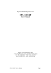
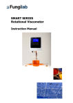
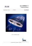
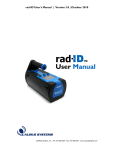
Bode 100 - Application Note Audio Amplifier Frequency Response By Tobias Schuster © 2015 by OMICRON Lab – V1.00 Visit www.omicron-lab.com for more information. Contact [email protected] for technical support. Smart Measurement Solutions® Bode 100 - Application Note Audio Amplifier Frequency Response Page 2 of 21 Table of Contents 1 EXECUTIVE SUMMARY ....................................................................................................................................... 3 2 MEASUREMENT TASKS ..................................................................................................................................... 3 3 MEASUREMENT SETUP & RESULTS ............................................................................................................... 4 3.1 SOUND SYSTEM DETAILS .............................................................................................................................................. 4 3.2 AMPLIFIER GAIN MEASUREMENTS ................................................................................................................................ 6 3.2.1 Bode 100 & Sound System Setup .................................................................................................................... 6 3.2.2 Measurement Setup ............................................................................................................................................ 9 3.2.3 Measurement Results ....................................................................................................................................... 10 Maximum, Minimum, Range and 50% of the Gain ................................................................................................. 10 Influence of treble, mid-range and bass level ......................................................................................................... 11 3.3 INPUT IMPEDANCE MEASUREMENT.............................................................................................................................. 13 3.3.1 One-Port Impedance Measurement ............................................................................................................... 13 3.3.1.1 Bode 100 & Sound System Setup ............................................................................................................... 13 3.3.1.2 Measurement Setup ...................................................................................................................................... 14 3.3.1.3 Measurement .................................................................................................................................................. 14 3.3.2 Measurement using a High Impedance Bridge ............................................................................................. 15 3.3.2.1 Bode 100 & Sound System Setup ............................................................................................................... 15 3.3.2.2 Measurement Setup ...................................................................................................................................... 16 3.3.2.3 Measurement Results.................................................................................................................................... 17 3.4 MEASURING THE OUTPUT IMPEDANCE........................................................................................................................ 17 3.4.1 Bode 100 & Sound System Setup .................................................................................................................. 17 3.4.2 Measurement Setup .......................................................................................................................................... 19 3.4.3 Measurement Results ....................................................................................................................................... 20 4 CONCLUSION ..................................................................................................................................................... 20 Note: Basic procedures such as setting-up, adjusting and calibrating the Bode 100 are described in the Bode 100 user manual. You can download the Bode 100 user manual at www.omicron-lab.com/bode-100/downloads#3 Note: All measurements in this application note have been performed with the Bode Analyzer Suite V2.43 SR1. Use this version or a higher version to perform the measurements shown in this document. You can download the latest version at www.omicron-lab.com/bode-100/downloads Smart Measurement Solutions® Bode 100 - Application Note Audio Amplifier Frequency Response Page 3 of 21 1 Executive Summary This application note explains how to measure frequency dependent characteristics of audio amplifiers with the Bode 100 and additional accessories. After a short introduction to the measurements we show how to configure the Bode 100 and how to connect the DUT1 for each measurement. 2 Measurement Tasks The following measurements are shown in this application note: Measurement of the amplifier’s gain range (maximum and minimum gain) Visualization of the equalizer settings’ influence and the 3 dB bandwidth Measurement of the input impedance of the sound system with and without a special high impedance bridge2 Measurement of the sound system’s output impedance The measurements are performed on a self-developed sound system. This sound system was developed by the teacher Dipl.-Päd. Ing. Michael Kvasznicza at the Federal Higher Technical Institute for Education and Experimenting in Bregenz. It was improved and extended with a Bluetooth connection to Android devices during a diploma thesis project. 1 Device Under Test Find more details on https://www.omicronlab.com/fileadmin/assets/customer_examples/Bode_Info_HighImpedance_V1_1.pdf 2 Smart Measurement Solutions® Bode 100 - Application Note Audio Amplifier Frequency Response Page 4 of 21 3 Measurement Setup & Results 3.1 Sound System Details The self-made sound system we are using for the measurements contains a preamplifier (TDA7439) and a self-made power amplifier. The input signal is modified in the preamplifier and can be set as desired via buttons on the housing of the sound system or via Bluetooth on an application for Android devices called “Blue Sound Control”3. Figure 1: Front view of the sound system Figure 2: Rear view of the sound system 3 This application for android smartphones is only usable with the corresponding sound system like the one we are using Smart Measurement Solutions® Bode 100 - Application Note Audio Amplifier Frequency Response Page 5 of 21 Figure 3: Settings of the sound system in the android app For reproducibility we use the smartphone app to change the settings as desired since the app directly displays the set values as numbers. The following settings that can be changed in the smartphone app: Range Maximum Minimum Step size Input Gain 30 0 2 Smart Measurement Solutions® Balance R 80 L 80 1 Treble +14 -14 2 Mid-range +14 -14 2 Bass +14 -14 2 Volume 0 -47 1 Bode 100 - Application Note Audio Amplifier Frequency Response Page 6 of 21 3.2 Amplifier Gain Measurements We can measure the maximum and minimum gain of the amplifier as well as the influence of the equalizer settings on the amplifier’s frequency response. Saving of the measurement results in the memory then allows us to quickly see the influence of the different settings. 3.2.1 Bode 100 & Sound System Setup We actually want to measure the voltage gain from the amplifier input to its output. There are two possibilities how to connect the Bode 100 to the amplifier. One is to use the Bode 100 as a vector network analyzer by using its “internal Reference”. We then can simply measure the gain by connecting the output of the Bode 100 to the input of the sound system and CH2 to the output of the sound system. However, because the input impedance of the sound system is not 50 Ω we will introduce an error. The error is estimated in the following: The input impedance of audio systems is generally very high. In our case the input impedance is >70 kΩ (see also 3.3 Input impedance Measurement). As shown below, the real input voltage present at the sound system input will be lower than the internal source voltage of the Bode 100. However, the difference is negligible (0.07% as calculated below). Therefore we can set the channel 1 input to “internal reference” and take the internal source voltage of the Bode 100 as reference signal. 𝑉𝑖𝑛 = 𝑉0 ⋅ 𝑅 𝑅𝐷𝑈𝑇 𝐷𝑈𝑇 +50 𝛺 70 𝑘𝛺 = 𝑉0 ⋅ 70 𝑘𝛺+50 𝛺 = 0.9993 ⋅ 𝑉0 → 0.07% Note: For this measurement you must perform a “thru” calibration before starting the measurement! The following settings are applied to the Bode 100 in the frequency sweep mode: Start Frequency: 10 Hz Stop Frequency: 100 kHz Sweep Mode: Logarithmic Number of Points: 201 Smart Measurement Solutions® Bode 100 - Application Note Audio Amplifier Frequency Response Page 7 of 21 Figure 4: Gain measurement configuration window For all gain measurement we set the channel 1 to internal reference, the attenuator CH1 to 0 dB and the receiver bandwidth to 100 Hz. We connect the loudspeakers for all measurements in order to operate the sound system under normal conditions. Attenuator CH2 is initially set to 40dB to avoid channel overload. In addition, trace 1 and 2 are set to measure Gain magnitude and phase as shown below: Figure 5: Gain measurement trace 1 & 2 settings Smart Measurement Solutions® Bode 100 - Application Note Audio Amplifier Frequency Response Page 8 of 21 The values that have been set for the following measurements are: Trace memory G30 V0 max 20dB4 G0 V-47 min G16 V-24 50% G10 V-24 G10 V-24 T14 G10 V-24 M14 G10 V-24 B14 G10 V-24 E14 Bode 100 settings Level in Attenuator dBm CH2 in dB -27 5 -20 0 -20 -20 -20 -20 40 0 20 20 20 20 20 20 Gain 30 0 16 10 10 10 10 10 Sound system settings MidBalance Treble range Bass Volume 0 0 0 0 0 0 0 0 0 0 0 0 14 0 0 14 0 0 0 0 0 14 0 14 0 0 0 0 0 0 14 14 0 -47 -23 -24 -24 -24 -24 -24 The Bode 100 source level and the attenuator CH2 are set to a value that the signal is high enough to get a noiseless measurement curve but not too high in order to avoid an overload at CH2. Therefore we always start with a small source level and a high attenuator at CH2 and change it afterwards to fight noise and to get a clean measurement result. 4 Additional 20 dB attenuator at the Bode 100 output and no loudspeaker connected since the gain is too high without the attenuator Smart Measurement Solutions® Bode 100 - Application Note Audio Amplifier Frequency Response Page 9 of 21 3.2.2 Measurement Setup For this measurement, we connect the sound system and the loudspeaker as well as the Bode 100 as shown in the picture below. Figure 6: Gain measurement - connection setup For the connection between the Bode 100 output and the sound system input, we use a BNC cable and a self-made BNC to 3.5 mm stereo audio connector (see Figure 7). Each of the two BNC-connectors are for either the left or the right input of the sound system. Smart Measurement Solutions® Bode 100 - Application Note Audio Amplifier Frequency Response Page 10 of 21 Figure 7: Audio connector to BNC connector 3.2.3 Measurement Results Before we start a measurement, we perform a THRU calibration. Maximum, Minimum, Range and 50% of the Gain TR1/dB 50 0 -50 -100 101 102 103 104 105 f/Hz G16 V-24 50% : Mag(Gain) G30 V0 max 20dB : Mag(Gain) G0 V-47 min : Mag(Gain) Figure 8: Gain measurement - minimum, maximum and 50 % In the measurement above, we measure the minimum and maximum amplification of the sound system and then we calculate the values we have to set to get 50 % of the gain. The minimum amplification at 1 kHz (sound system settings: G0 V-47 min) results in a gain of -23 dB. The maximum amplification at 1 kHz (sound system settings: G30 V0 max 20 dB) results in a gain of 34 dB +20 dB = 54 dB (we added a 20 dB attenuator at the Bode 100 output) The gain range of the sound system therefore is: |𝑔𝑎𝑖𝑛𝑚𝑖𝑛 | + 𝑔𝑎𝑖𝑛𝑚𝑎𝑥 = 23 𝑑𝐵 + 54 𝑑𝐵 = 77𝑑𝐵 . Smart Measurement Solutions® Bode 100 - Application Note Audio Amplifier Frequency Response Page 11 of 21 Influence of treble, mid-range and bass level To visualize the influence of the equalizer settings, a high variety of measurements could be done. As an example, we choose an input gain of 10 and set all equalizer settings (treble, mid-range and bass) to 0. 40 20 TR1/dB 0 -20 -40 -60 -80 -100 101 102 103 104 105 f/Hz G10 V-24 : Mag(Gain) Figure 9: Gain measurement - equalizer neutral Then, we do four more measurements with different equalizer settings and safe the curves into different memories. Figure 10: Trace 1 settings - memory function We can save the measurement curve to the memory by pressing the Button “Data -> Memory1”. Furthermore, we can add some more memory spaces and change the name of e.g. “Memory 1” in the tab “Memory”. Smart Measurement Solutions® Bode 100 - Application Note Audio Amplifier Frequency Response Page 12 of 21 To see the differences of each measurement, we add the other four measurements to the existing curve. The changes we make in the four additional measurement curves are: 1 Treble +14 (G10 V-24 T14) 2 Mid-range + 14 (G10 V-24 M14) 3 Bass + 14 (G10 V-24 B14) 4 Treble, Mid-range and Bass + 14 (G10 V-24 E14) 30 TR1/dB 25 f/Hz TR1/dB Cursor 1 134,658 6,959 1 20 15 10 5 0 101 102 103 104 105 f/Hz G10 V-24 : Mag(Gain) G10 V-24 M14 : Mag(Gain) G10 V-24 E14 : Mag(Gain) G10 V-24 T14 : Mag(Gain) G10 V-24 B14 : Mag(Gain) Figure 11: Gain measurement - equalizer maximum As shown in the diagram above, the 3 dB bandwidth of the curve with all equalizer parameters set to 0 starts at approx. 135 Hz and is very flat until the end of the x-axis at 100 kHz. If we want to improve the low-bandwidth we could increase the bass (see curve G10 V-24 B14). The curves display quickly in what frequency range the equalizer changes the frequency response of the amplifier and how much the corresponding frequency range (bass, treble and mid-range) is amplified when the equalizer values are set to a maximum (see curve G10 V-24 E14). Smart Measurement Solutions® Bode 100 - Application Note Audio Amplifier Frequency Response Page 13 of 21 3.3 Input impedance Measurement 3.3.1 One-Port Impedance Measurement 3.3.1.1 Bode 100 & Sound System Setup To measure the input impedance we perform a logarithmic frequency sweep from 10 Hz to 100 kHz and use the maximum Bode 100 output level (13 dBm) for maximum sensitivity. The other setup parameters can be seen in the following: Figure 12: Standard input impedance measurement - configuration window Figure 13: Standard input impedance measurement - trace 1 settings Smart Measurement Solutions® Bode 100 - Application Note Audio Amplifier Frequency Response Page 14 of 21 Before we start the measurement we perform a user calibration (OPEN, SHORT, LOAD) to get the best possible result. In addition we have to switch the sound system on to ensure that all active components are up and running like during normal operation. 3.3.1.2 Measurement Setup To measure the input impedance we connect the Output of the Bode 100 to the input of the sound system. Figure 14: Standard input impedance measurement - connection setup 3.3.1.3 Measurement 1 2 TR1/Ohm 100K 80K 60K 40K 20K f/Hz TR1/Ohm Cursor 1 20,000 96,491k Cursor 2 20,000k 71,789k C2-C1 19,980k -24,702k 101 102 103 104 105 f/Hz Memory 2 : Mag(Impedance) Figure 15: Standard input impedance measurement - frequency sweep The measurement shows that the input impedance reaches very high values. The one-port impedance measurement method is recommended up to approximately 10 kΩ whereas our sound system has a much higher input impedance. This is the reason for the noise on the measurement that shows the limits of this measurement method. To improve this measurement we can use a special setup that improves the sensitivity for high impedance values as shown in the next section. Smart Measurement Solutions® Bode 100 - Application Note Audio Amplifier Frequency Response Page 15 of 21 3.3.2 Measurement using a High Impedance Bridge 3.3.2.1 Bode 100 & Sound System Setup If we use the high impedance bridge5 we have to set the Bode 100 to the “frequency sweep (external coupler)” mode: The start and stop frequency, the sweep mode and the output level are just the same as for the oneport measurement. The other settings can be seen in the following pictures. Figure 16: Input impedance with high impedance bridge – configuration window 5 Find more details on https://www.omicronlab.com/fileadmin/assets/customer_examples/Bode_Info_HighImpedance_V1_1.pdf Smart Measurement Solutions® Bode 100 - Application Note Audio Amplifier Frequency Response Page 16 of 21 Figure 17: Input impedance with high impedance bridge - trace 1 settings 3.3.2.2 Measurement Setup For this measurement we use the high impedance bridge and connect it between the Bode 100 and the sound system as we can see in the pictures below. Figure 18: Input impedance with high impedance bridge - setup front view Smart Measurement Solutions® Bode 100 - Application Note Audio Amplifier Frequency Response Page 17 of 21 3.3.2.3 Measurement Results Before we could start the measurement, we have to do an OPEN, SHORT and LOAD calibration. 1 2 TR1/Ohm 100K 80K 60K 40K 20K f/Hz TR1/Ohm Cursor 1 20,000 98,468k Cursor 2 20,000k 69,644k C2-C1 19,980k -28,823k 101 102 103 104 105 f/Hz white input : Mag(Impedance) Figure 19: Input impedance with high impedance bridge - frequency sweep The measurement result shows that the input impedance starts at 98 kΩ at 20 Hz and reduces to 70 kΩ at 20 kHz. Since the input impedance in datasheets are mostly measured at 1 kHz, we also want to know the value at this frequency. The input impedance of an audio amplifier at 1 kHz should be > 10 kΩ and typically is between 10 kΩ and 100 kΩ for a bridging6 impedance of the output and the input (𝑅𝐼𝑁 ≫ 𝑅𝑂𝑈𝑇 ). Therefore an input impedance of 96 kΩ at 1 kHz is very good. 3.4 Measuring the Output Impedance 3.4.1 Bode 100 & Sound System Setup We have to set the Bode 100 to measure the impedance like the way we did in 3.3.1 on page 13. The Bode 100 is set in the frequency sweep mode as follows: Start Frequency: 10 Hz Stop Frequency: 100 kHz Sweep Mode: Logarithmic Number of Points: 201 Source Level: 13 dBm Attenuator CH1: 10 dB Attenuator CH2: 10 dB If the load impedance is 10 times or more the source impedance, this is called a „bridging” impedance. 6 Smart Measurement Solutions® Bode 100 - Application Note Audio Amplifier Frequency Response Page 18 of 21 Receiver Bandwidth: 10 Hz Figure 20: Output impedance measurement - trace 1 settings Smart Measurement Solutions® Bode 100 - Application Note Audio Amplifier Frequency Response Page 19 of 21 3.4.2 Measurement Setup To measure the output impedance of the sound system, we have to connect the output of the Bode 100 to the output of the sound system. The input of the sound system is short-circuited to reduce noise at the input and to protect the Bode 100 of an output signal from the sound system. Please take care of the maximum reverse power of the Bode 100 which can be seen in the user manual. Figure 21: Output impedance measurement setup Figure 22: Output impedance measurement - input Smart Measurement Solutions® Bode 100 - Application Note Audio Amplifier Frequency Response Page 20 of 21 3.4.3 Measurement Results 0,10 0,09 TR1/Ohm 0,08 1 2 f/Hz TR1/Ohm Cursor 1 20,000 29,042m Cursor 2 20,000k 53,173m C2-C1 19,980k 24,131m 0,07 0,06 0,05 0,04 0,03 0,02 101 102 103 104 105 f/Hz OUTPUT : Mag(Impedance) Figure 23: sound system output impedance measurement The output impedance of the sound system is between 29 mΩ at 20 Hz and 53 mΩ at 20 kHz. Since the impedance of the loudspeakers should be much bigger than the audio output of the sound system they are connected to, the output of the sound system is typically < 100 mΩ and in our case approx. 34 mΩ at 1 kHz. 4 Conclusion The Bode 100 is a test set that allows to measure a high variety of important sound system parameters in a simple and fast way. Input and output impedances of the sound system or the different settings of the equalizer can be visualized as well as the amplifier’s gain range and its 3 dB bandwidth. If you are interested in sound system measurements, check out our application note “Loudspeaker and Audio Crossover Measurements”. In this application note is described how to measure the impedance of loudspeakers and how to characterize audio crossovers. Smart Measurement Solutions® Bode 100 - Application Note Audio Amplifier Frequency Response Page 21 of 21 OMICRON Lab is a division of OMICRON electronics specialized in providing Smart Measurement Solutions to professionals such as scientists, engineers and teachers engaged in the field of electronics. It simplifies measurement tasks and provides its customers with more time to focus on their real business. OMICRON Lab was established in 2006 and is meanwhile serving customers in more than 40 countries. Offices in America, Europe, East Asia and an international network of distributors enable a fast and extraordinary customer support. OMICRON Lab products stand for high quality offered at the best price/value ratio on the market. The products' reliability and ease of use guarantee trouble-free operation. Close customer relationship and more than 25 years in-house experience enable the development of innovative products close to the field. Europe, Middle East, Africa OMICRON electronics GmbH Phone: +43 59495 Fax: +43 59495 9999 Asia Pacific OMICRON electronics Asia Limited Phone: +852 3767 5500 Fax: +852 3767 5400 Americas OMICRON electronics Corp. USA Phone: +1 713 830-4660 Fax: +1 713 830-4661 [email protected] www.omicron-lab.com Smart Measurement Solutions®