1
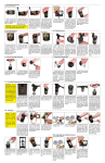
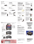
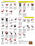
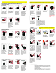
90.9 Series Nitrogen Gas Spring Repair Instructions
I. Exhausting Pressure
Self-Contained Mode
1. W h e n e x h a u s t i n g
pressure, position gas
spring horizontally with port
up for safety.
Linked Mode
2. Remove Por t Plug
(90.607.110 or 90.505.110).
Retain parts for use during
reassembly.
CAUTION: Always wear safety goggles
when performing maintenance work.
3. Keeping face and hands
clear of port, use Valve
Bleed Tool (90.360.4)
or Por t Ser vicing Tool
(90.320.8) to depress
Compact Valve (90.260).
Cover port with a cloth to
absorb discharge.
4. After all gas pressure is 1. Exhaust nitrogen gas
exhausted, be sure piston by opening bleed valve on
rod will freely extend and control panel.
retract into tube manually.
If not, try depressing valve
again. If still unsuccessful,
STOP and contact DADCO.
Self-Contained Mode
2. Remove Compact Valve
(90.260) by unscrewing it
with the Port Servicing
Tool (90.320.8).
2. Once cartridge and rod
are removed from Tube
Assembly, slide cartridge
off of rod and discard.
Retain rod for inspection
and reuse.
3. Replace damaged
Compact Valve. Use Port
Servicing Tool (90.320.8)
to thread new Compact
Valve (90.260) into the port
until it fits snugly on the
seat. Avoid over torquing
the valve.
5. Insert C-Style Retaining
Ring (90.285.x) into
re ta i n i n g r i n g gro ove
using C-Ring Installation
Tool (90.352) or standard
bench tools. Be sure CStyle Retaining Ring is
fully seated in retaining
ring groove.
1. Check port for deposits or
burrs and clean thoroughly.
Inspect service fitting and
replace if it shows signs of
damage. Lubricate threads
and seals on fitting and
thread into the gas spring
port.
1. Stand the gas spring
upright. Make sure rod is
retracted in tube. Place
removal sleeve (90.340.x)
over rod. Tap sleeve until
Dust Cover (90.246.9.x) is
loosened. Remove Dust
Cover and discard.
V. Cleaning & Inspection
1. Lightly polish rod surface
with emery cloth (600 grit).
Inspect finish of rod for
scratches or gouges. If
rod is damaged, it must be
replaced.
VI. Cartridge Replacement & Reassembly (continued)
4. Place rod and cartridge
assembly into the tube. To
release any back pressure,
depress compact valve.
Position top of cartridge
just below retaining ring
groove. DO NOT force the
cartridge down further into
the tube.
2. Reposition Removal
S l e eve a n d c o n t i n u e
tapping until rod cartridge
assembly is slightly below
retaining ring groove. DO
NOT force the cartridge
down further into the Tube
Assembly.
3.
Remove C-st yle
Retaining Ring (90.285.x)
using C-Ring Removal Tool
(90.356). Position hooked
end of tool below c-ring.
For best results locate tool
near either end of c-ring.
Linked Mode
IV. Rod & Cartridge Removal
1. To remove Rod and
Cartridge Assembly thread
a T-Handle (90.320.2)
into rod end. Pull entire
assembly out of tube. The
spring body can be held in
a vise (with soft jaws) while
pulling out the assembly.
3. Unthread service fitting
and wipe with a clean
cloth. Proceed to “II. Port
Maintenance” Linked Mode,
step 1.
III. C-Ring Removal
II. Port Maintenance
1. The compact valve
usually does not need
replacing. If it appears
damaged, is leaking or
sticking proceed to step 2,
otherwise leave the valve
undisturbed and proceed
to “III. C-Ring Removal.”
2. Verify all pressure
is relieved by manually
re t r a c t i n g p i s to n ro d
into tube. If rod will
not fully retract, release
remaining pressure. If still
unsuccessful, STOP and
contact DADCO.
6 . T h r e a d T- H a n d l e
(90.320.2) into end of
piston rod. Pull up on
T- H a n d l e u n t i l to p o f
cartridge is completely
past c-ring. The rod must
seat cartridge assembly
fully before charging. The
housing should be flush
with end of cylinder. Make
sure rod is extended to
its proper stroke length.
(Depress the compact
valve to facilitate full rod
extension.)
2. Inspect Tube Assembly
for damage, especially
around opening. Lightly
polish scratches at mouth
of Tube Assembly to avoid
damaging seals during
reassembly. If damage to
Tube Assembly is severe,
it must be replaced. Wash,
clean and dry the inside
thoroughly.
VI. Cartridge Replacement & Reassembly
CAUTION: Before
starting reassembly
p ro c e s s , b e s u re
repair area is clean.
It is imperative that
the gas spring be free
of all contaminants
upon reassembly. If
this precaution is not
taken, it may lead to
premature gas spring
failure.
1. Choose appropriate
repair kit (90.109.x) for
specific model you are
repairing. The repair kit
number is laser marked on
back of the Tube Assembly.
NOTE: Repair kits are not
interchangeable among
models.
3. Lubricate the inside
wall of the tube with entire
contents of the bottle of
assembly oil.
Self-Contained Mode
Linked Mode
1S. Thread the Quick
Disconnect Filler Valve
(90.310.143 or 90.310.111)
into port of gas spring.
Connect female end of
charging assembly to
charging nipple. The
DADCO Pressure Analyzer
(90.315.5) can also be used
for charging, discharging
and gauging pressure.
1L. Pipe all gas springs back
to the control panel, making
sure that all connections are
tight and that gas spring rods
are extended.
Self-Contained or Linked Mode
2L. Attach the Charging 3. Open main valve on
Assembly (90.310.040 or nitrogen tank.
90.310.045) to the quick
disconnect filler valve on the
control panel.
4. Set desired charging
pressure on regulator.
VIII. Adjusting Gas Spring Pressure
Self-Contained or Linked Mode
6. Disconnect charging
assembly from charging
nipple. The small amount
of nitrogen trapped between
shut-off valve and filler
valve will bleed off as you
disconnect fitting.
2. Position the Cartridge
Assembly over the rod,
making sure wiper end
marked “TOP” is facing
up. While holding cartridge
vertically, slide it down the
rod to the rod retainer. Be
careful not to force cartridge
at an angle as seal could
become damaged.
NOTE: For best results, use the DADCO Charging Assembly which has a shut off
valve and Quick Disconnect Adapter at the end of the hose.
VII. Charging
VII. Charging (continued)
5. Slowly open shutoff valve and allow gas
spring to reach the desired
charging pressure. After
spring has been charged to
desired pressure, CLOSE
HOSE SHUT-OFF VALVE
AND TANK SHUT-OFF
VALVE.
4. Once hooked end of
tool is firmly seated below
c-r ing, begin pushing it
toward outside of gas spring
can. The handles will close
naturally and c-ring will be
extracted as you complete
this motion.
Self-Contained or Linked
Self-Contained Mode
7. Check for leaks at top of
tube around rod and at base
around valve compartment
by using vegetable oil or
water.
8S. Verify pressure with
a DADCO Load Cell using
a Po r t a bl e Te s t S t a n d
(90.305.3) or arbor press.
9S. Make sure Compact
Valve (90.260) is in place
and thread Por t Plug
(90.607.110 or 90.505.110)
securely over top.
10. Install new Dust Cover
(90.246.9.x). Tap with a
soft mallet until top of Dust
Cover rests flush with top of
can. The rod wiper should
be visible.
1. To increase spring
pressure, thread Quick
Disconnect Filler Valve
(90.310.143 or 90.310.111)
into port, set regulator to
d e s i re d p re s s u re a n d
fill. DADCO’s pressure
analyzer (90.315.5) may
also be used to adjust
pressure.
2. To decrease gas spring
pressure, depress valve
stem using a Valve Bleed
Tool (90.360.4).
90.9 Series Parts List
90.9.03000 – 90.9.07500
Piston Rod
90.215.9.       .
Model
Dust Cover
90.246.9.
Stroke
Rod Wiper
90.248.9.
Model
Model
C-Style Retaining Ring
90.285.
**O-ring Backup Ring
90.249.
Model
Model
Cartridge Assembly
90.230.9.
**O-ring
90.245.
Model
Model
Tube Assembly
90.205.9.      .
Model Stroke
G 1/8 Port Plug
90.505.110
Compact Valve
90.260
90.9.01500
M6 Port Plug
90.607.110
Compact Valve
90.260
Replacement Part Ordering Example:
Models: 01500, 03000, 05000, 07500
Piston Rod: 90.215. 9. 01500. 025
Part Number
Series
The 90.9 Series Repair Kit includes:
**Included in Cartridge Assembly.
Cartridge Assembly..90.230.9.
Dust Cover................90.246.9.
Assembly Oil.............90.289.1
Stroke (mm)
Model
NOTE: DADCO’s 90.9 Series Nitrogen Gas Springs are
permanently marked with model number, serial
number and repair kit number. Please refer to
these when ordering replacement parts.
Model
Model
A step-by-step maintenance manual is also included.
Repair Tools
C-Ring Installation Tool • 90.352
To insert the C-style retaining ring into the
retaining ring groove.
Removal Sleeve • 90.340.
(01500, 03000, 05000, 07500)
To position the cartridge below the
C-ring groove when assembling or
disassembling a gas spring.
Valve Bleed Tool • 90.360.4
C-Ring Removal Tool • 90.356
Use the DADCO Valve Bleed Tool to slowly
discharge a spring to the desired pressure.
To remove the C-style retaining ring safely in a
single controlled motion.
Standard Load Cell • 90.300.
(01500, 03000, 05000, 07500)
T-Handle • 90.320.2 (M8 thread)
When used with a Portable Test Stand, the
Standard Load Cell gives precise
measurement of gas spring
charging pressure. Request
bulletin # 97B119G.
To remove the piston rod when
disassembling and position
correctly when reassembling.
®
Nitrogen Gas Spring
Maintenance Instructions
90.9 Series
ed
u
tin
–
n
o
c
is
–D
Port Servicing Tool • 90.320.8
Quick Disconnect Charging Nipple
90.310.143 (M6: Model 01500)
90.310.111 (G 1/8: Models 03000 – 07500)
To perform all necessary servicing to the valve
compartment.
Use the DADCO Quick Disconnect Charging
Nipple to charge 90.9 Series Gas Springs.
Portable Test Stand • 90.305.3
90.310.143
90.310.111
Charging Assembly • 90.310.040
Use the DADCO Quick Disconnect Charging
Assembly with the charging nipple or pressure
analyzer to charge self-contained gas springs.
It can also be used with a
DADCO control panel for
charging linked systems.
©DADCO, Inc. 2010 • All Rights Reserved
Use the Portable Test Stand in
conjunction with a Standard Load Cell
for precise measurement of gas spring
force. For more information, request
bulletin #97B121.
DADCO Pressure Analyzer • 90.315.5
Use the DADCO Pressure Analyzer to easily
charge, discharge, and gauge
the pressure in DADCO’s 90.9
Series Gas Springs.
Bulletin No. B02111A
Comprehensive Guide
This service manual is a simple step-by-step
maintenance guide for DADCO 90.9 Series
Nitrogen Gas Springs. Proper repair requires
careful examination of all component parts
and replacement of any that are worn or
damaged. All DADCO replacement parts
are available from factory stock.
Note: Nitrogen Gas Spring repair varies
slightly from model to model and by mode of
operation (self-contained or linked). As you
proceed through the basic steps outlined in
this bulletin, take care to follow the instructions
pertaining to your model. All DADCO Gas
Springs are permanently marked with model
and serial number. Please refer to these
numbers when performing repair work and
when ordering replacement parts.