1
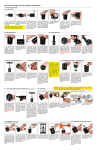
Service Tools
C-Ring Installation Tool
90.352 (U.2600-U.9600)
90.352.10000 (U.20000)
C-Ring Removal Tool
90.356
To remove the C-style retaining
ring safely in a single controlled
motion.
Standard Load Cell
90.300.2600 (Models: U/UH/UT/UX.2600)
90.300.4600 (Models: U/UH/UT/UX.4600)
90.300.6600 (Models: U/UH/UT/UX.6600)
90.300.9600 (Models: U/UT/UX.9600)
90.300.20000 (Models: U/UX.20000)
To insert the C-style retaining ring
into the retaining ring groove.
When used with a Portable Test Stand,
the Standard Load Cell gives precise
measurement of gas spring charging
pressure. Each model requires its
specified load cell. For more information
contact DADCO.
Valve Bleed Tool
90.360.4
Port Servicing Tool
90.320.8
Quick Disconnect Charging Assembly
90.310.040
Use the DADCO Valve Bleed
Tool to slowly discharge a
spring to the desired pressure.
To perform all necessary servicing to
the valve compartment.
Use the DADCO Quick Disconnect Charging
Assembly with the Filler Valve or Pressure
Analyzer to charge self-contained gas
springs, or with a DADCO Control
Panel for charging linked systems.
For more information contact
DADCO.
Removal Sleeve
90.340.01500 (Models: U/UH/UT/UX.2600)
90.340.03000 (Models: U/UH/UT/UX.4600)
90.340.05000 (Models: U/UH/UT/UX.6600)
90.340.07500 (Models: U/UT/UX.9600)
T-Handle
90.320.2 (M8)
90.320.10 (M10)
Quick Disconnect Charging Nipple: Self Contained
90.310.143 (M6 Port)
90.310.111 (G 1/8 Port)
To remove the piston rod when
disassembling and position
correctly when reassembling.
Use the DADCO Quick Disconnect Charging Nipple to
charge DADCO Nitrogen Gas Springs.
To position the cartridge assembly below
the C-ring groove when assembling or
disassembling a gas spring.
90.310.143
Portable Test Stand
90.305.3
Use the Portable Test Stand in
conjunction with a Standard Load Cell
for precise measurement of gas spring
force on contact. Excludes use with
the U.9600 and U.20000. For more
information request bulletin 97B121.
DADCO Pressure Monitor
90.421.1 (120 VAC) – bulletin B00136
.2 (240 VAC) – bulletin B01115A
.2D (24 VDC, SPDT) – bulletin B00134A
The DADCO Pressure Monitor indicates
if pressure drops below a pre-set level,
alerting the press controller to shut
down the press. The shutdown point
is adjustable between 15 and 200
bar (200-3000 psi). For additional
information request the appropriate
bulletin.
DADCO Pressure Analyzer
90.315.5 (M6 and G 1/8 bits)
Use the DADCO Pressure Analyzer to easily charge,
discharge, and gauge the pressure in DADCO’s
U Series. This tool can take the
place of the Valve Bleed Tool,
Standard Load Cell, Quick
Disconnect Filler Valve,
and Portable Test Stand.
For more information
request bulletin B01133D.
90.310.111
Digital Load Cell
90.305.BG (Meter)
90.305.LC.50 (222 kN Load Cell)
The DADCO Digital Load Cell Meter
can display force in Newtons, Kg or lbs.
The 90.305.LC.50 (supplied with the
connector) may be used to measure
gas spring force up to 50,000 lbs. Other
digital load cell units are
available, for more
information request
bulletin B04106B.
DADCO Electronic Pressure Monitors
DADCO’s Electrical Pressure Monitors
indicate if pressure drops below a
preset level, alerting the press
controller to shut down the press.
They are available in a variety of
configurations to suit a variety of
applications. For more information
request bulletin B10105 or
contact DADCO.
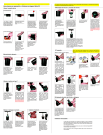
Parts List
All DADCO gas springs are permanently marked with model and serial number. Please refer to these numbers for corresponding
repair kits when ordering replacement parts.
Piston Rod
90.215.
.
Bulletin No. B06127A
®
.
Series Model Stroke
Wiper
Dust Cover
90.246.U.
Model
C-Style Retaining Ring
Model Part Number
2600 90.285.01500
4600 90.285.03000
6600 90.285.05000
9600 90.285.07500
20000 90.285.10000
O-Ring Backup Ring
O-Ring
UltraPak® Cartridge
90.200.U.
Model
Tube Assembly
90.205.
.
.
Comprehensive
Guide
This service manual is a simple step-by-step
maintenance guide for DADCO’s Ultra Force® and
Ultra Force Extended® Nitrogen Gas Springs
Models: U.2600−U.20000 / UH.2600−UH.6600 /
UT.2600−UT.9600 / UX.2600−UX.20000.
Series Model Stroke
U.4600 - U.9600
UH.2600 - UH.6600
UT.2600 - UT.9600
U.2600–U.20000
UH.2600–UH.6600
UT.2600–UT.9600
UX.2600–UX.20000
Proper repair requires careful examination of all
component parts and replacement of any that are
worn or damaged. All DADCO replacement parts
are available from factory stock.
Compact Valve
90.260
Port Plug
90.505.110
Nitrogen Gas Spring
Maintenance Instructions
Ultra Force® and
Ultra Force Extended®
Models:
Typically, DADCO Nitrogen Gas Springs can be
rebuilt in less than ten minutes by replacing only
one part, the factory pre-assembled cartridge
assembly.
U.2600
After reviewing this maintenance guide, if you
require any additional training or have any
questions please contact DADCO for assistance.
T20 6-Lobe Drive
90.296
Compact Valve
90.260
Sealing Washer
90.252
U.20000
UX.2600 -UX.20000
Port Plug
90.505.110
Note: All DADCO gas springs are permanently marked with
model and serial number. Please refer to these numbers
for corresponding repair kits and when ordering
replacement parts.
Cartridge Valve
90.265
Repair Kits
Includes a fully assembled cartridge, dust cover, bottle of assembly oil and
a maintenance manual.
Model
Kit Number
UH
UT
Series
UX
U
2600
90.108.2600
UH
UT
UX
U
4600
90.108.4600
UH
UT
UX
U
6600
90.108.6600
–
UT
UX
U
9600
90.108.9600
–
–
UX
U
20000
90.108.20000
Ordering Example:
Models: 02600. 04600, 06600,
09600, 20000
90.215.
U.
2600.
All DADCO bulletins and catalogs are available for download from
our web site, www.dadco.net.
025
Part No. Series Model Stroke (mm)
©DADCO, Inc. 2013 • All Rights Reserved
®
43850 Plymouth Oaks Blvd.
Plymouth, Michigan USA 48170
1.734.207.1100 • 1.800.323.2687
Toll Free: 1.800.DADCO.USA
Fax: 1.734.207.2222
www.dadco.net
CAUTION: Always wear safety goggles when performing any maintenance work.
NOTE: Before starting the reassembly process, be sure the repair area is clean. It is imperative that the gas spring be free of all
contaminants upon reassembly. If this precaution is not taken it may lead to contamination and premature gas spring failure.
U Series Nitrogen Gas Spring Repair Instructions
VI. Cartridge Replacement and Reassembly
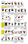
I. Exhausting Pressure
Self-Contained Mode
1. When exhausting pressure,
position the gas spring
with the port up for safety.
2. Remove the Protective
Screw, (90.505.110 or 90.296).
Retain parts for use during
reassembly.
3. Keeping face and hands
clear of the port, use the Valve
Bleed Tool, (90.360.4), or Port
Servicing Tool, (90.320.8), to
depress the Compact Valve
stem, (90.260), or Cartridge
Valve, (90.265). Cover the
port with a cloth to absorb
discharge.
4. After all of the gas pressure
is exhausted, be sure that the
piston rod will freely retract
into the tube manually. If not,
try depressing the valve again.
If still unsuccessful stop and
contact DADCO.
3. Lubricate the inside wall of
the tube with all of the DADCO
Assembly Oil.
1. Choose the appropriate
repair kit. The repair kit number
needed is laser marked on the
back of the Tube Assembly.
NOTE: Repair kits are not
interchangeable among
models.
2. Position the Cartridge
Assembly over the rod, making
sure that the wiper end is facing
up. While holding the
cartridge vertically slide the
cartridge down the rod to the
rod retainer. Be careful not to
force the cartridge at an angle
as the seal could become
dislodged.
5. Insert the C-Style Retaining Ring in the retaining ring
groove using a DADCO C-Ring
Installation Tool, (90.352 or
90.352.10000). Be sure the
C-Style Retaining Ring is fully
seated in the retaining ring
groove.
6. Thread the T-Handle, (90.320.2
or 90.320.10), into the end of
the piston rod. Pull up on the
T-Handle until the top of the
cartridge is completely past the
c-ring. The rod must seat the
cartridge assembly fully before
charging. The housing should be
flush with the end of the cylinder.
Make sure the rod is extended to
its proper stroke length. (Depress
the needle valve to facilitate full
rod extension.)
4. Place the rod and cartridge
i n to t h e Tu b e A s s e m bly.
Use the Valve Bleed Tool,
(90.360.4), or Port Servicing
Tool, (890.320.8), to depress
the needle valve to release any
back pressure. Position the
top of the cartridge just below
the retaining ring groove.
Open Flow Mode
1. Exhaust nitrogen gas by
opening the bleed valve on the
control panel.
2. Verify that all pressure is
relieved by manually retracting
the piston rod into the tube. If
the rod will not fully retract
release the remaining
pressure. If still unsuccessful
stop and contact DADCO.
3. Unthread the service fitting
and wipe with a clean cloth.
Proceed to “II. Port
Maintenance” Open Flow
Mode step 1.
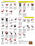
VII. Charging
Self Contained
Note: For best results, use the DADCO Charging Assembly which has a shut
off valve and Quick Disconnect at the end of the hose.
Open-Flow Mode
II. Port Maintenance
Self-Contained
Open-Flow Mode
Self contained spring with a
90.310.143 shown.
1. Generally the valve does
not need replacing. Only if the
valve appears damaged, is
leaking pressure or sticking
proceed to step 2, otherwise
leave the valve undisturbed
and proceed to “III. C-Ring
Removal.”
2. Remove the Compact Valve,
(90.260), or Cartridge Valve,
(90.265), by unscrewing it
with the Port Servicing Tool,
(90.320.8).
3. Thread a new Compact
Valve, (90.260), or Cartridge
Valve ( 90.265), into the
port until it fits snugly on the
seat. Avoid over torquing the
valve.
1. Check the port for deposits
or burrs and clean thoroughly.
Inspect the service fitting and
replace if it shows signs of
damage. Lubricate threads and
seals on the fitting and thread
the service fitting into the gas
spring port.
1. T h r e a d t h e Q u i c k
D i s c o n n e c t Fi l l e r Va lve,
(90.310.143 or 90.310.111),
into the port of the gas spring.
Connect the female end of
the charging assembly to the
charging nipple. The DADCO
Pressure Analyzer, (90.315.5),
can also be used for charging,
discharging and gauging
pressure in self contained
gas springs.
1. T h r e a d t h e D A D C O
Pressure Analyzer (90.315.5)
into the por t of the gas
spring and open the valve.
For a detailed explanation
of how to use the DADCO
Pressure Analyzer see bulletin
B01133D. Connect the female
end of the charging assembly
to the male quick disconnect.
4. After the spring has been
charged to the desired pressure,
CLOSE THE HOSE SHUTOFF VALVE AND TANK SHUTOFF VALVE. Disconnect the
charging assembly from the
charging nipple. The small
amount of nitrogen trapped
between the shut-off valve and
filler valve will bleed off as you
disconnect the fitting.
5. Check for leaks at the top
of the tube around the rod and
at the base around the valve
compartment by using mineral oil
or water to test for leaks. Verify the
pressure of self contained spring
models 2600−6600 with a DADCO
Load Cell using a DADCO Portable
Test Stand, (90.305.3). Verify the
pressure of self contained spring
models 9600 and 20000 using a
DADCO Load Cell and an arbor
press. NOTE: If spring is open-flow
mode, then a DADCO Pressure
Analyzer, (90.315.5), may be used
to verify pressure and must remain
in place during testing.
2. Open the main valve on the
nitrogen tank. Set the desired
charging pressure on the
regulator. Do not exceed the
maximum charging pressure
of 150 bar (2175 psi).
3. Slowly open the shut-off
valve at the end of the charging
hose and allow the gas spring
to reach the desired charging
pressure.
Self Contained
III. C-Ring Removal
1. Stand the gas spring
upright. Place a removal
sleeve, (90.340.x), longer than
the stroke over the rod. Tap
the sleeve until the Dust Cover,
(90.246.U.x), is loosened.
Remove the Dust Cover and
discard.
2. Reposition the DADCO
Removal Sleeve and only
continue tapping until the rod
cartridge assembly is slightly
b e l ow t h e re t a i n i n g r i n g
groove.
3. Remove the C-style Retaining
Ring, (90.285.x.), using a C-Ring
Removal Tool, (90.356) . Position
the hooked end of the tool below
the c-ring. For best results locate
the tool near either end of the
c-ring.
IV. Rod & Cartridge Removal
V. Cleaning & Inspection
1. To remove the Rod and
Cartridge Assembly thread
a T-Handle, (90.320.2 or
90.320.10), into the rod end.
Pull the entire assembly out
of the tube. The spring body
can be held in a vise (with
soft jaws) while pulling out the
assembly.
1. Lightly polish the rod surface
with an emery cloth (600 grit).
Inspect the finish of the rod for
any scratches or gouges. If the
rod is damaged it must be
replaced.
4. Once the hooked end of the
tool is firmly seated below the
c-ring, begin pushing it toward
the outside of the gas spring
can. The handles will close
naturally, and the c-ring will
be extracted as you complete
this motion. For a detailed
explanation of c-ring removal
see bulletin 97B110.
6. Install the new Dust Cover,
(90.246.U.x). Tap with a soft
mallet until the top of the Dust
Cover rests flush with the top of
the can. The rod wiper should
be visible.
7. Securely re-install the
Protective Screw, (90.505.110
or 90.296).
VIII. Adjusting Gas Spring Pressure
1. To increase the spring
pressure, thread the Quick
D i s c o n n e c t Fi l l e r Va lve,
(90.310.143 or 90.310.111),
into the port, set the regulator
to the desired pressure and fill.
DADCO’s Pressure Analyzer,
(90.315.5), may also be used
to adjust pressure.
2. To decrease the gas spring
pressure, depress the valve
stem using a DADCO Valve
Bleed Tool, (90.360.4), or a
DADCO Pressure Analyzer,
(90.315.5).
IX. Linked Systems
2. Once the cartridge and rod
are removed from the Tube
Assembly slide the cartridge off
the rod and discard. Retain the
rod for inspection and reuse.
2. Inspect the Tube Assembly
for any damage, especially
around the mouth of the Tube
Assembly. Lightly polish out
any scratches at the mouth
of the Tube Assembly to
avoid damaging seals during
the reassembly process. If
damage to the Tube Assembly
is severe it must be replaced.
Wash, clean and dry the inside
thoroughly.
After testing all springs for leaks, the open-flow springs are ready to be re-linked in the system. If possible, once the springs are all linked back
to the control panel, leave the system to sit fully charged overnight. If pressure has dropped indicating a leak verify that each connection is tight
and test each fitting for a leak.
Contact DADCO for information on converting a self-contained DADCO Nitrogen Gas Spring to a linked system.
NOTE: DADCO U/UH/UT/UX Series Nitrogen Gas Springs should not be linked with the valve installed.