1
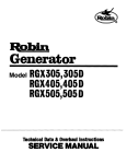
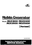
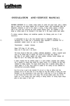
CONTENTS
Title
Section
Page
1.
SPECIFICATIONS
2.
EXTERNAL
3.
................................................
VliWS
..............................................
3
..............................................
3
2-l.
Model
RGD551
2-2.
Model
RGD1101
PERFORMANCE
3-1.
3-2.
Model
Model
5.
OPERATION
6.
WIRING
..
Phase
3 phase
Generator
Generator
For Single Phase, 2 Wires Generator
For Single Phase, 4 Wires Generator
CHECKING
SHOOTING
FUNCTIONAL
PARTS
13
13
...............................
...............................
. . . . . . . . . . . . .. . . . . . . . .
... ... . .... ... .. .. ....
. ... ... ... ...
.. ... .. .
.. ... .. ... .
Stator
8-2.
8-3.
Rotor/&y
Voltmeter
...................................................
9.
10.
8.9.
SR Assy
....................................................
Injection
of Residual
DISASSEMBLING
SAFETY
AND
PRECAUTlONS
Magnetism
. ..
15
15
16
16
16
16
16
.................................
REASSEMBLING
15
15
15
B-4. Neon Lamp ..................................................
8.5. Slip Rings ...................................................
8-6. Brush Assy ..................................................
8-7. AVR Assy (Single phase) .......................................
...........................................
8-8. CT Assy (3 phase)
8-l 0.
14
15
Assy ..................................................
..................................................
8-l.
13
13
..................................
6-2.
6-3.
8.
12
12
.........................................
............................................
.. ... . ..... ... ... .. .... ... ... .. .. ... ... .. .... .
DIAGRAM
11
. . . . . . . . . . . . . . . . . . . . . . . . . . . . . . . . . . . . . . . . . . . . . . 12
For 3 Phase, 4 Wires Generator
TROUBLE
8
.. ... ... .. ... .. .... .. .. ... .... ... .. ... .. .... ..
6-l.
7.
5
.............................................
.. ...
Single
5
.........................................
..............................................
RGD551
RGDllOl
CONSTRUCTION
4
.............................................
CURVES
4.
5-l.
5-2.
1
.. ... .... .. ... ... ... .. .... . .
.... .. ... ... ..
..
... .. ..
.. .. .. .. ... .
18
23
1. SPECIFICATIONS
RGD551
Model
Self exciting,
2 pole
I
/ Type
Single phase,
Single phase, 2 wires
3 phase, 4 wires
4 wires
I
50Hz
L :
a :
Max.
E I output
E !
u’
Rated
50Hz
i
60Hz
(VI
5000VA
Current
(A)
2201380
.230/400
7.6
Revolution
(rpm)
7.0
60Hz
4ooow
I
.I271220
! 2401415 I120/208
7.2
: 50Hz
I
4500w
5500VA
110
I
:
120
36.4
’
33.3 :
I
: Voltage
/ Rated
60Hz
I
,
13.9
13.1
I
I
220
110
: 36.4
18.2
240
17.4
1 16.7
3000
3600
3000
i
230
!
3600
i
i
llOl220
36.4118.2
/ 3000 ; 3600
I
i Power
0.8
Factor
1 .o
!
Air-cooled,
Type
4cycle.
Singlecylinder
I
Diesel Engine
DY40-A
Model
I
I
Piston
Displacement
402cc (24.53)
fcu.in)
E
.e :. Maximum
w
Fuel
a PS
Horsepower
Diesel Oil
Fuel Tank
Capacity
15i
(3.96)
(U.S. gal.)
Starting
Starting
System
Motor
I
output
Output
Terminal
Output
4
Terminal
2
Terminal
Terminal
Output
Socket
Output
2
CT type
Voltage
Protection
Breaker
fluctuation
Breaker
I
Dry Weight
flbs)
Dimensions
LxWxHfinchl
fluctuation
I
Breaker1
:
!lP 37A.
140kg
Breaker
(309)
al lx598x773mm(31.9x23.5x30.4~
-l-
3P 15A
:
Output
/
Socket
2
type
Voltage
+5%
3P 7.3A
Socket
AVR
I
Regulator
Voltage
Circuit
4
!
1P 18A
Breaker
~5%
Breaker;
/lP37A’lP35Aj
Breaker
2P 1BA
2
I
-
,Model
I
RGDllOl
I-
Self exciting,
2 pole
Type
1 Single phase,
3 phase, 4 wires
Single phase, 2 wires
4 wires
’ Frequency
50Hz
50Hz
60Hz
1 Max.
60Hz
11 OOOVA
50Hz
1 60Hz
I
9ooow
output
1 OOOOVA
Voltage
(VI
2301400
2201380.
Current
(A)
Rated
Revolution
15.2
(rpm)
!
14.4
aooow
2401415
I
1201208
13.9
3000
I
’ 1271220 I:
26.2
27.8
3600
I
I
’
110
1
72.7
220
1I 230
240
110
120
1101220
36.4
I 34.8
33.3
72.7
66.7
72.7136.4
3000
/
3600
3000 : 3600
I
Power
Factor
0.8
1 .o
,
Aircooled,
Type
4cycle.
Model
Piston
2cylinder
I
Diesel Engine
DYBO-2A
Displacement
a04cc
(49.06)
(cu.in)
Maximum
Horsepower
16PSl3000rpm
Fuel
Diesel Oil
Fuel Tank
Capacity
24C (6.34)
(U.S. gal.)
Starting
Starting
System
Output
Terminal
Motor
4
Output
Terminal
output
2
Terminal
4
output
Output
Socket
Output
2
Socket
2
/ Socket
I
CT type
Voltage
Voltage
Breaker
Circuit
AVR
type
Regulator
Protection
Dry Weight
(Ibs)
Dimensions
LxWxHfinch)
3P 16A
I
1
1 Breaker
!
fluctuation
=5X
Voltage
-Breaker/Breaker
3P 15A
Breaker
3P 30A
lP 75A’lP
220kg
96lx650xB72mm
-2-
.Breaker
37Aj
(485)
(37.8x25.4x34.3)
fluctuation
1P 35A
+5%
Breaker
-lP 75A’lP
Breaker
Breaker
70A’
2P 37A
2
’
2. EXTERNAL
0
2-1.
Model
-EXTERNAL
VIEWS
RGD551
VIEW
(1)
/
!
Air cleaner
Pipe frame
Fuel tank
\
\
i
!
i
Decompression
lever
(
I
Fuel tank cap!
Fuel gauge,
Control
i
\
\
let
\
\
Control
box
i
‘!,
:.: i:.
,I I,
CA
Oil filler
Gel filter
0
Earth cord /
\Oil
filter
I
Caster /
EXTERNAL
VIEW
(2) - CONTROL
PANEL
(VIEW
“A”)
vibration
isolator
.. AC voltmeter
,No-fuse
Neon lamp
Rubber
:
/
breaker
;Terminal
cover
For 3 phase, 4 wires Generator
Output
For single phase, 2 wires Generator
socket
For single phase, 4 wires Generator
2-2
Model
EXTERNAL
RGDllOl
VIEW
(1)
Air cleaner
,Engine
:
‘?
Control
iPipe frame
:-Decompression
;
.!;
:
lever
I!
,
.
Fuel tank I
Fue! tank cap ,. ‘.
:
.
lever
Muffler
/
:Fuel gauge
Control
9
/
t i
Oil filler
Rubber
Caster .’
EXTERNAL
VIEW
(2) - CONTROL
PANEL
(VIEW
“A”)
isolator!
AC voltmeter
,No-fuse
Neon lamp 1
vibration
:’
/
breaker
;Terminal
cover
output
Ij ,n
! QJb
Output
terminal
‘j
D
’0
0 0 0
For 3 phase, 4 wires Generator
Neon lamp.
For single phase, 4 wires Generator
For single phase, 2 wires Generator
-4-
box
3. PERFORMANCE
0
3-1
Model
CURVES
RGD551
l Self exciting,
80%
........................................
Engine
Output
Max
...............................
Rated
............................
Voltage ........................................
53
I
j
:
power
Factor
Engine
Output
Rated
Frequency
Voltage
Engine
Output
............................
Frequency
22OV/38OV
Voltage
l Self exciting,
power
E.ngine
Output
:
o3
/
Max
Voltage
(A) 6
8
100%
DY40-A
..............................
45OOW
............................
...................................
4OOOW
50Hz
1 1ov/22ov
.......................................
5000
4500
I
5
E
50
Tu.Ez
49
10
2 pole, single phase, 4 wires
53
j
I
230/400\/
_^I
-Li
I- 32
51
I
5500
’
:
5OHz
........................................
Frequency
I
&
5000VA
...............................
Rated
240\1/4 15V
-L
Factor
550()VA
I
woe
............................
..................................
2
Current
Dy40-A
!
5500VA
1
:
50Hz
53
Dy4f-JA
...............................
........................................
5000VA
...................................
Y
435 ---vi
425 -
Max
Rated
80%
...............................
8056
........................................
5OHz
2 pole, 3 phase, 4 wires
...............................
Wuency
2 pole, 3 phase, 4 wires
...............................
10
.......................................
52r-F
51m
Factor
(A) La
........................................
Max
bY40-A
5500VA
I
;
!
2
Curren:
l Self exciting,
power
5000VA
..................................
Frequency
l Self exciting,
2 pole, 3 phase, 4 wires
power Factor ...............................
1
/I
.--^
4,“”
4ooo3
3500 ;
4000
1
3000
230
220
210
12345678910
Current (A)-
2500° 5
5
(10)
Current
-5-
~10~
(20)
(A)&
15
(30)
20
(40)
~~~,
-
l Self exciting,
Power Factor
Engine..
2 pole, single phase, 2 wires
................................
Frequency
DY4@A
Engine
Output
Rated
4O()()w
.............................
....................................
I
10
l Self exciting,
Power Factor
Engine
20
30
Current (A)-
Voltage
Voltage
...............................
....................................
5
l Self exciting,
joey;,
Power Factor
DY40-A
Engine
45OOW
Output
........................................
10
15
Current (A)-
20
1
25
1(-jay<
DY40-A
.........................................
Rated
50Hz
22OV
2 pole, single phase, 2 wires
...............................
Max
45()(&V
4o()()\Jv
........................................
50
4(-J(-JOW
....................................
.............................
!
!
2 pole, single phase, 2 wires
...............................
Output Max ..................................
Rated
Frequency
1lOV
40
DY4()-A
Max ................................
Rated
.
1()0X
..........................................
50Hz (60Hz)
T.
2 pole, single phase, 2 wires
...............................
I
..........................................
Frequency
Power Factor
45()OW
........................................
Voltage
loo?6
Max ................................
.........................................
Output
l Self exciting,
...............................
45OOW
.............................
4O()()W
50Hz
Frequency
23OV
Voltage .........................................
...................................
50Hz
240~
53
52
-4500
-4000
-3500
-3000
-2500
-2000
-1500
I
5
10
Current (AIF
I
I
15
20
25
5
-6-
10
Currenr
15
IAl-
20
25
_
l Self exciting,
Output
Max
0 Self exciting,
2 pole, 3 phase, 4 wires
Power Factor ...............................
Engine ..........................................
...............................
Rated ..............................
Frequency .....................................
........................................
Voltage
DY40-A
Engine
5500VA
Output
2 pole, 3 phase, 4 wires
80%
...............................
Power Factor
80%
..........................................
Max
DY4@A
...............................
55OOVA
Rate-J .............................
5OOOV A
5000VA
(j(-jHz
...................................
60Hz
Frequency
J~OV!~O@J
Voltage .........................................
63
I
127V,i22OV
I
-3500
I
/
Current
l Self exciting,
Power Factor
Engine
Output
-3000
I
2500
-2500
Current
(A)-
2 pole, single phase, 4 wires
...............................
..........................................
l Self exciting,
100%
Power Factor
DY4@A
Engine
Max ................................
45OOW
Output
Rated ..............................
4OOOW
Frequency
....................................
Voltage. ........................................
60Hz
Voltage
2 pole, single phase, 2 wires
...............................
..........................................
100%
DY40-A
...............................
45OOW
Rated ..............................
4OOOW
Max
Frequency
1 1OV/22OV
iA)-
....................................
........................................
60Hz
12ov
63
62
61
61
4500
60
4000
59
-4500
60.
-4000
59
-3500
3500
3000
230
220
210
I
2500
5
(10)
Current
IO
(20)
15
/30!
20
(40)
25
(50)
10
(A)-
-7-
20
30
Current IAl-
40
50
3-2
Model
RGDllOl
l Self exciting,
2 pole, 3 phase, 4 wires
l Self exciting,
2 pole, 3 phase, 4 wires
Power Factor
..__._...._....___.______________
80’$&
Power Factor
.................................
._.____.____.._.............................. Dy80-2A
Engine
Output
Max
. .. .. ... .. .. . .. . ... .. .. ... . .. .. ..
Rated
Frequency
._........_...................
Engine
1 1000VA
Output
Frequency
. ...____.......____.................... 50Hz
N
521
i
,
-
:
DY80-2A
.................................
Max
Rated
1 OOOOVA
. . .... . .. .. . . ... ... . .. .. . .... .. . .. .. . .... . 22OVl38OV
Voltage
.............................................
..............................
.......................................
1 1 (-J-J-Jv,~,
1 OOOOVA
5()Hz
230/400\1
..........................................
Voltage
80%
I
-.-
I50000
/
I f
2
4
6
Current
8
I
10 12 14 16 18 20
(A)-
o Self exciting,
2 pole, 3 phase, 4 wires
Power Factor
.................................
l Self exciting,
80%
Power Factor
2 pole, single phase, 4 wires
.................................
l(-J(-J%
.............................................
Dy80-2A
Engine
.............................................
Dy80-2A
Engine
Output
Max
1 lOOOVA
Output Max ....................................
....................................
Rated
Frequency
Voltage
.................................
.......................................
..........................................
xI
53
I 2z$
IL
50
52
51
49
Rated .................................
1 O(-jO()VA
50Hz
Frequency
24OV,‘41 5V
Voltage
.......................................
iI
8OOOW
5()Hz
1 1 OV!22OV
.............................................
53
9OOOW
I
10000~
11000
9000 6>
L
80001
7000 2
=
435
425
415
405
230-Voltage
/
220
210
/
y_
7 50006
6000 5
7
z 1,201
“‘g1100;
I1 10;.
,
Voltage
/
Y
3
>
2
4
Current
6
8
5 10 15 20 25 30 35 40 45 50
i301
(SOi
‘7Oi
igoi
ilO!
i2oj i40,
iE.0: 18Oi ilOO!
10 12 14 16 18 20
(A)-
Current
-8-
(A) -
I
0
l Self exciting,
2 pole, single phase, 2 wires
l Self exciting,
2 pole, single phase, 2 wires
Power Factor
_._....__........................
Power Factor
.................................
Engine
.. ... .. .. .. . ..._..._.........................
Output
Max
Voltage
zzI
Output Max ....................................
Rated
___._.._..._..................... 8000W
.. .. ..._...............................
.. .. . .. .. . . .._...__....................
.............................................
Engine
DY80-2A
___.._______._._.___................
9OOOW
Rated
Frequency
100%
Frequency
50Hz (60Hz)
1 1 ov
.................................
.......................................
..........................................
Voltage
100%
D’,‘8@2/,
g()()OW
8OOOW
5()Hz
22ov
(62152
g (61151
: (60150
=I
$ (59!49
LL
120
-110
>
-100
8
J
! 2
I
I
20
40
Current
l Self exciting,
60
80
Y
I
100
10
(A) -
40
50
Curren?(A)-
2 pole, single phase, 2 wires
.................................
100%
0 Self exciting,
2 pole, single phase, 2 wires
Power
. .. .. ... .. .. .. .. .. .. ... . . .. . ... .. 100%
Power Factor
Engine .............................................
Dy80-2A
Engine
... .. . . ... .. .. . .. . . .... .. . .. .. . .. .. .. . ... . .. . DY80-2A
Output Max ....................................
9OOOW
Output
Max
Rated .................................
80(3)W
Frequency
............... -.......................
Voltage ............................................
Factor
.. . .. .. . .. ... .. .. ... . .. .. .. .. .. .. .. . 9OOOW
Rated
50Hz
Frequency
23OV
Voltage
. . .. .._...__._._._............... 8000~
. ... . . . .. .. .._.._......................
50Hz
___.........._.._._..........................
240V
,800O
.6000 2
-5000 ‘;:
2 t
-4000 2
.3000$
I
230
I z5 220 /:
g,210
s
>
,
30
40
1
50
kkren?(A)-
Current
-9-
(A) -
l Self exciting,
Power Factor
Engine
Output
2 pole, 3 phase, 4 wire
.........................................
Max
Rated
Frequency
l Self exciting,
80%
...............................
...............................
.............................
Power Factor
DY8@2A
Engine
1 1 OO()VA
Output
Voltage .........................................
8()9&
..........................................
Dy8()-2A
Max ................................
Rated ..............................
1 OOOOVA
....................................
2 pole, 3 phase, 4 wires
...............................
60Hz
Frequency
12OV,l208V
Voltage
....................................
........................................
1 lOOOVA
1OOOOVA
60Hz
127Vi22oV
62
61
-11000
11000
60
59
8000
z
$
2
Z
t >
210
220
6000
7000
5000
2
L
-8000
8000
-6000
6000
120
130
l Self exciting,
20
(A)-
-7000
7000
220
2
5
- t
0
140
10
Current
-9000
9000
230
130
I/
-10000
10000
59
9000
5000
I
30
40
Current
l Self exciting,
2 pole, single phase, 4 wires
10(-J?&
IAl-
2 pole, single phase, 2 wires
...............................
100%
..............................
Power Factor
.........................................
Engine
Dy80-2A
Engine
Output
Max ................................
9OOOW
Output
Rated .............................
8OOOW
800(34/
6()Hz
Frequency
Voltage ......................................... 12(-J/
Frequency
Voltage
....................................
.........................................
DY80-2A
Max ................................
Rated
gOO()W
............................
...................................
6()Hz
1 1ov/22ov
........................................
63
Power Factor
I
631
I
;
62
/
61
/
---loo
ac
.n,-.
8Guu
60
.8000
59
-7000
7000
6000
5000
!
I
20
30
40
(80)
60
20
50
(100)
Cur%
w
-lO-
(A)-
80
100
4. CONSTRUCTION
(2)
The Generator
control
box
frame.
(RGD551
and
a fuel
The stator
cover
which
stator,
engine.
frame
available
ard for
is directly
rubber
Control
bolts
to
the
engine.
with
coupling
The
for RGD551
The
(The fuel
voltmeter,
a neon lamp,
terminals,
control
box
regulator
assembly
inside
A 2-pole
and
and
is
a no-fuse
a terminal
equipped
(AVR),
breaker,output
cover.
with
or a current
an
automatic
transformer
(3)
AC voltmeter,
\
voltage
output
(CT) and diode
is
is
coil
for excitation
coupled
with
CONTROL
secured
on the rotor
with
bolts
a coup1 ing and coupling
is cooled
of
and
is wound
by the engine’s
to the
plate.
cooling
fan.
load
Variations
in the load
voltage
to the 2 output
sockets
of the output
are automatically
regulator
(AVR)
and the 2
voltage
controlled
due to
by the
or the current
trans-
breaker
Terminal
coves
,Stator
’
is attached,
which
terminals.
changes
former
(CT).
no-fuse
breaker
When overloads
(N.F.B.)
;
thus protecting
The engine
is started
with
circuits
occur,
and cut-off
the generator.
the starting
motor
and stopped
lever.
cover
PANEL
Brush assy
Brush holder
Slip ring
SECTIONAL
VIEW
Rubber
i
vibration
isolator
Note
CT (Current
transformer)
..... CTcontrols
output voltage to maintain it at rated voltage.
SR (diode stack) ...... SR converts alternate current generated at secondary coil to direct current, and transfers it to rotor coil.
N. F. B. (No-fuse breaker)--.
When overloads
or short circuits
occur,
the N.F.B.
will operate to cut-off the output voltage.
A VR (Automatic
voltage regulator) ......’ A VR automatically
controls output
voltage when change in the load makes output
voltage
vary.
-ll-
the
the out-
Engine cover
cover
! Front
or short
will operate
put voltage,
Stator
terminal
assembly
which
with the engine control
Output
Inside the
the brush
and lead wires)
is supported
The load is connected
automatic
,No-fuse
‘\
and
by the collar
is directly
Connecting
of the
stack (SR).
Neon lamp
the electricity.
to which
plate,
(output
the rear cover and by the flywheel
rotor
The generator
an AC
sockets
The inside
brush
coils
is sunk to receive the ball bearing.
engine flywheel
box are mounted
generate
stator
on the engine side.
and as a stand-
tank bands.)
panel of the control
the
is a holder
springs,
rotor
situated
is
with
which
there
and the collar
in the pipe
in the pipe frame.
coils),
(brushes,
the
which
is wound
rear cover,
to the
battery,
stator
auxiliary
to a pipe
Inside
are installed
isolators.
is also installed
The
a
a rear cover and a front
connected
equipment
of a stator,
box
On the front
and
cover,
with
and the engine
as an optional
RGDllOl,
consists
attached
bolts
vibration
tank is secured with
(1)
with
The generator
using
tank
has a stator
is fixed
a rotor
& RGDllOl)
Generator
5. OPERATION
5-1 Single phase Generator
When the engine is started,
as a result
poles,
of the
a minute
induced
rotor
the rotor
residual
voltage
voltage
assembly
magnetism
increases
passes through
the
the excitation
rated
voltage.
indicate
the
(N.F.B.)
is thrown
until
At
rated
of the
is induced
this
in the
the AVR
coil; this increases the induced
rotates
magnetic
stator.
which
voltage
point
the
voltmeter
no-fuse
When
the
OFF
while
the
further
the induced
voltage.
This
and excites
voltage
ON from
and,
reaches
will
breaker
generating,
the
neon lamp will light.
Should
the speed change due to variations
terminal
voltage
action
of
will
the
always
AVR
in the load, the
be kept constant
which
increases
through
the
or decreases
the
excitation.
5-2 Three phase Generator
When the engine
as a result
poles,
of the
a minute
induced
the
is started,
rotor
further
coil;
residual
voltage
voltage
this
increases
thrown
in the
the induced
until
magnetic
stator.
When
ON from
OFF
while
the
change
due
will
always
voltage
the induced
At this point
voltage.
and
This
the CT and SR to excite
the excitation
rated
rotates
of the
is induced
reaches the rated voltage.
the
assembly
magnetism
passes through
increases
indicate
the rotor
which
voltage
the voltmeter
the no-fuse
generating,
will
breaker
is
the neon
lamp
in the
load,
will light.
Should
the terminal
the
action
speed
voltage
of the
CT which
tovariations
be kept constant
increases
through
or decreases
the
excitation.
Since the induced
the rotor,
voltage
the voltage
is proportional
can be adjusted
to the speed of
by controlling
the
speed.
-12-
6. WIRING
0
DIAGRAM
Blue
6-1
For 3 phase, 4 wires Generator
Brown
6-2 For single phase, 2 wires Generator
63
For single‘phase,
4 wires Generator
-I-
Blue
Blue
L
A
u
V
U’
V’
a
B
Black
I
I
Name of-Parts-
II
Symbols
1
Stator
coil (output)
II
c
1
AC outout
Stator
coil (auxiliary)
II
p
I
Plug-in
Rotor
coil.(excitation)
II
B
I
Brush
CT-
I
SR
1
Symbols
Y!?
No-fuse
breaker
Automatic
voltage
II
regulator
11
AC voltmeter
PL
i__
UY
Neon
T
lamp
AC output
~
terminal
-13-
Name of Parts
pin terminal
~GrrentLansfoYmer
Diode
Output
I
socket
I
(red)
~
I
1
I
stack
terminal
Pl
Plug-in pin terminal
(blue)
P2
Plug-in.pin
(red)
terminal
-7. TROUBLE
SHOOTING
Phenomenon
1.
Generator
Remedy
Cause
will not generate.
1. Disconnection
plug-in
or poor contact
3. Break in the rotor
load cannot
is normal,
but rated
Generated
higher
5.
Repair or replace.
coil circuit.
:o Replace.
.z Replace.
AVR,
1. Faulty
CT or SR.
of slip ring.
o
Repair or replace.
magnetism.
c
Induce
or poor contact
2. Faulty
insulation
3. Faulty
AVR,
CT or SR.
4. Poor contact
of brushes.
of output
anew.
,o Repair or replace.
is greatly
than rated voltage.
1. Erroneous
2. Faulty
=: Repair or replace.
of coil windings.
output
.o Repair or replace.
of engine.
:
c
Repair or replace.
i
2
Adjust
3
Correct.
o
Replace.
o
Adjust.
wiring.
AVR
i
or CT.
3. Over-speeding
4.
o
terminals.
be applied.
voltage
of brushes.
5. Faulty
5. Low power
3.
Repair or replace.
:z Replace.
7. No residual
voltage
o
4. Break in the stator coil circuit.
6. Distortion
No-load
;
pin terminals.
2. Wear or poor contact
2.
of
of engine.
or repair.
Voltmeter
needle will not move, or
1. Faulty
voltmeter.
-2 Repair or replace.
indication
is faulty.
2. Faulty
lead wire.
c
Replace.
Generator
is generating,
1. Faulty
neon lamp.
lamp will not light.
but neon
2. Faulty
3. No-fuse
lead wire.
breaker
-14-
in wrong
position.
.:
Replace.
I
!
o
Replace.
l
o
Turn to ON.
0
8-l
Stator
Assy
(3 phase)
a.
With
the
lead, all lead wires
blue
lead wire
are tested
for
as the common
continuity
tester.
If all lead wires show continuity:
(Single
phase, 2 wires) With the white
b.
common
for continuity
(Single
a
lead wire as the
lead, the blue and red lead wires are tested
with
continuity:
c.
with
OK.
a tester.
If these lead wires show
OK.
phase, 4 wires)
blue and yellow
In addition
lead wires
to the above,
are tested
If all lead wires show continuity:
the
i Stator
for continuity.
assy
OK.
8-2 Rotor Assy
If there
is continuity
slip rings:
when
a tester
is applied
to the two
OK.
(The resistance
is 6 to 10 ohms for single phase, and 10 to
50 ohms for 3 phase.)
8-3 Voltmeter
Give an alternating
meter
84
current
If volt-
voltage to a terminal.
shows the given voltage:
OK
Neon Lamp
If the
lamp
applied
lights
when
a voltage
to the lamp terminals:
of about
AC 1OOV is
OK.
8-5 Slip Rings
If the surface of the slip rings is uniformly
Slip rings showing
wear should
The
while
slip
the rotor
spots, excessive
OK.
About
AC
wear, or uneven
be repaired.
ring
turning
Care should
black
bright:
should
the rotor,
be polished
until
w/th
the rough
be taken to prevent
fine
sandpaper,
spots disappear.
the sandpaper
Voltmeter
touching
coils.
Neon lamp i
AC1 OOV
..:‘/sout
“Sandpaper
-l5-
8-6 Brush Assy
If the surface
this
in contact
surface
surface
with
is rough,
the slip ring is clean:
repair
of the slip ring will
using
OK. If
fine sandpaper.
also be rough,
(The
so polish
this
Brush assy
with
fine sandpaper
Brushes
should
12mm from
8-7 AVR
also.)
be replaced
the contact
when
worn
to a height
of
(Standard
surface.
Service
Assy (single phase)
If the epoxy
AVR
cover protecting
is clean:
discoloured
OK.
(The
the functional
AVR
parts of the
is faulty
if the cover
is
or burnt.)
8-8 CT Assy (3 phase)
When continuity
3 and 4, with
is shown
a tester:
(The CT is faulty
between
terminals
1 and 2, and
OK.
if continuity
is shown
between
terminals
2 and 3.)
8-9 SR Assy
If no continuity
lead
wires
continuity
wires:
is shown
of
the
is shown
OK.
with
a tester
3 yellow
lead
for one only
(If both
applied
wires:
to any 2
OK.
Also,
if
of the green or red lead
show continuity,
the SR assembly
is
faulty.)
8-10
4
Injection
The
of Residual
source
minute
of
electric
electricity
after
completely
disappear,
Also,
when
residual
Methods
(a)
power
generated
Sometimes,
CT
Magnetism
of
the
generator
by the residual
long disuse the residual
the
and will
rotor
magnetism
has
magnetism.
magnetism
have to be newly
been
is the
replaced,
may
injected.
injection
of
box
and
will be necessary.
for inducing
residual
magnetism.
3 phase Generator
(1)
When a battery
Remove
is available.
the
disconnect
cover
the two
of
the pin terminals
body
and the SR. Then
through
or
2
from
connecting
the generator
residual
magnetism
from
coil lead wires
the generator
seconds,
connected
green and brown,
by passing a current
the rotor
coming
control
lead wires,
from
be induced
the
so that
the
the battery
(the lead wires
body),
green
to (+) and the brown
Diode stack CSFI)~’
can
for about
lead
1
wire
is
lead wire to (-I
of the battery.
After
induction
its former
state.
is finished,
restore
Use a battery
the wiring
to
of 72 to 48 V .
-16-
limit
18mm)
12mm
0
(2)
When an AC power
While
line is available.
operating
the
generator,
power
line to the generator
series
resistance
of
disconnect
the
voltmeter
deflects.
Use an AC power
terminals
from
AC
apply
10 to
power
the
through
50 ohms,
line
as soon
line near the rated
3 phase Generator
AC
a
and
as the
voltage
of
the generator.
(b)
Single Phase Generator
(1)
When a battery
Remove
is available.
the
cover
disconnect
the two
connecting
the
of
the
lead wires,
generator
the pin terminals.
control
black
body
Then
box,
by connecting
the battery
wires
from
the generator
body
seconds,
so that
connected
the
green
can
to the lead
for
to (+) and the black
from
magnetism
be induced
2
and green,
and AVR
residual
and
about
lead
1 to
wire
is
lead wire to (-)
of the battery.
After
0
induction
its former
is finished,
to
-AC
power
line
of 12 to 48V.
When an AC power
line is available.
While
operating
power
line to the output
through
the wiring
state.
Use a battery
(2)
restore
the
generator,
the
voltmeter
deflects.
AC
Use an AC power
the
AC
Single phase Generator
socket of the generator
a series resistance
disconnect
apply
of 10 to 50 ohms, and
power
line
as soon
line near the rated
as the
voltage
of
the generatoc
CAUTION:
REFER
RELATION
NOT
OF
EXCEED
I
TO
THE
FOLLOWING
TABLE
VOLTAGE
AND
RESISTANCE
A SECOND
FOR
EXCITING.
VOLTAGE
I
:
RESISTANCE
loo-12ov
10R
200-240V
20,0,
36O-45OV
409
0 lac
FOR
R. DO
I
R
I
R(lO-
-17-
50.0.!
a.111
.
+AC
.
power
line
9. DISASSEMBLING
AND REASSEMBLING
COMPONENT
1. Battery
DISASSEMBLING
1) Disconnect
2) Remove
3) Remove
nuts from
battery
4) Demount
2. Fuel tank
battery
PROCEDURE
cords from(+)
battery
fitting
battery
DISASSEMBLED
from
terminals.
fitting
bracket.
Nut M6 - 2 ea.
I
Spring washer M6 - 2 ea.
’
Washer M6 - 2 ea.
bracket.
frame.
1) Drain fuel.
(Fuel tank capacity
2) Disconnect
fuel pipe from
Battery
fitting
bracket
’
Battery
fitting
bolt - 2 ea.
:
Battery
-
-
1 ea.
1 ea.
I
= 24 E)
upper part of fuel tank
by hand, and fuel pipe from
PART
Banjo bolt - 1 ea.
Gasket - 2 ea.
lower part by loosen-
ing banjo bolt.
3) Remove
nuts and screws from
fuel tank bands
that secure fuel tank.
3. Control
box
4) Remove
fuet tank bands.
5) Demount
fuel tank from
1) Remove
bolts from
frame.
control
;
Nut M6 - 8 ea.
/
Band clip - 4 ea.
/
ScrewM6x3-4ea.
!
Fuel tank band assy - 2 ea.
I
box cover.
I
Fuel tank -
1 ea.
Bolt M4 x 10 - 6 ea.
Spring washer M4 - 6 ea.
2) Remove control
3) Disconnect
*
lead wires extending
The number
between
box cover.
and color
out of yoke.
of wires are different
3 phase units and single phase units.
Wires are also connected
to different
connec-
I
i
Control
:
For 3 phase units only
’
box cover - 1 ea.
Screw M4 x 10 - 3 ea.
Washer M4 - 3 ea.
Nut M4 - 3 ea.
tors.
4) Remove
bolts and nuts that fasten control
box to
Bolt M5 x 30 - 4 ea.
Nut M5 - 4 ea.
frame.
Spring washer M5 - 4 ea.
5) Demount
control
box from
frame.
-18-
Control
box - 1 ea.
DISASSEMBLING
COMPONENT
4. Brush assy
1) Remove
bolts that fasten
2) Remove
brush cover.
l
When separating
separate
3) Loosen
l
5. Rubber
vibration
isolator
(Battery
DISASSEMBLED
PROCEDURE
/ Bolt M5x
brush cover.
brush cover,
not to remove
brush assy.
1) Remove
nuts from
vibration
isolator
1 ea.
I
Nut M4 - 2 ea.
nuts that fasten brush assy.
4) Remove
2ea.
/ Brush cover lead wires from
them one by one in order of thickness.
Use caution
lo-
PART
nuts.
Brush assy - 2 ea.
top and bottom
underneath
of rubber
Nut M8 - 4 ea.
Spring washer M8 - 4 ea.
yoke.
Washer M8 - 2 ea.
cord (-) )
Nut M8 - 4 ea.
Spring washer
M8 - 4 ea.
Washer M8 - 4 ea.
3) Disconnect
4) Lifting
(-)
up yoke,
battery
remove
cord.
rubber
vibration
-19-
isolator.
Rubber
vibration
isolator
- 2 ea.
COMPONENT
6. Yoke,
Stator
Front
cover,
I
DISASSEMBLING
1) Remove
PROCEDURE
bolts that fasten front
I
cover to engine.
Bolt Ml0
PART
x 25, P = 1.25
- 8 ea.
Rear cover,
Stator
DISASSEMBLED
cover,
2) Separate
yoke from
1 Spring washer Ml0
!
- 8 ea.
; Pentagonal
bolt M8 -4
engine.
Brush holder
l
Use caution
3) Remove
front
not to damage slip ring of rotor.
pentagonal
through
bolts that fasten
cover and rear cover to stator,
4) Remove stator cover fastening
through
Spring washer M8 - 4 ea.
/ Screw M4 x 25 - 2 ea.
screws.
Spring washer M4 - 2 ea.
i Washer M4 - 2 ea.
i Nut M4 - 2 ea.
I
5) Remove stator
6) Remove front
cover.
cover and rear cover from
stator.
Stator
cover -
Stator
-
Front
cover -
1 ea.
1 ea.
1 ea.
i Rear cover - 1 ea.
7) Remove
brush holder
screws from
rear
ScrewM5x20-2ea
1 Spring washer M5 - 2’ea.
cover.
1 8) Remove
fastening
brush holder.
! Brush holder
assy -
1 ea.
ea.
DISASSEMBLING
COMPONENT
7. Rotor
1) Remove
assy,
Coupling
DISASSEMBLED
PROCEDURE
bolts that fasten coupling
! Bolt M8 x 20 - 6 ea.
plate to
Spring washer
flywheel.
plate
PART
M8 - 6 ea.
Washer M8 - 6 ea.
2) Remove
*
rotor
When placing
caution
3) Remove
Rotor
assy.
rotor
assy after removing,
assy -
1 ea.
use
not to damage slip ring and coil.
bolts that fasten coupling
plate to
; BoltM8x20-6ea.
j Spring washer M8 -6
coup1 ing.
ea.
1 Washer M8 - 6 ea.
4) Separate
coupling
plate from
coupling.
Coupling
Rotor
Coupling
7. Rotor
assy
Ball bearing
.
::
\
‘S!ip
ring
‘Coil
plate,
plate -
- 1 ea.
1 set (3 pcs.) ea.
-
COMPONENT
DISASSEMBLING
1) Demount
8. Engine
l
engine from
When demounting
PROCEDURE
’ Engine -
frame.
engine,
DISASSEMBLED
I
use firm
tools like
PART
1 ea.
i (F rame) -
1 ea.
a chain block.
9. Rubber
isolator,
vibration
I) Remove
Caster,
vibration
bolts and nuts that fasten rubber
isolator
For casters
Bolt M8 x 25 - 14 ea.
and casters to frame.
Screw
Earth cord
M8 x 25 -
Nut M8 -
2ea.
16 ea.
Spring washer M8 Washer M8 For rubber
16 ea.
16 ea.
vibration
isolator
Nut M8 - 4 ea.
Spring washer M8 - 4 ea.
2) Remove rubber
vibration
isolator,
casters and
A unit has 2 front
rotary
vibration
isolator
- 2 ea.
earth cord.
l
Rubber
fixed
casters and 2 rear
Caster - 4 ea.
Earth cord - 1 ea.
casters.
9 Earth cord,
‘\\
9 Rotary
3
To reassemble
generator,
C When disassembling
make the disassembling
and reassembling,
procedures
in the reverse sequence.
please refer to Parts Catalog.
-22-
caste:
. . /
10. SAFETY
(1)
PRECAUTIONS
Never place inflammable
objects
0
oil,
Avoid
placing
light
inflammable
(2)
Attention
should
hazards,
and very
avoided
near the generator.
When
be paid
dusty
working
in closed
should
power
in by cables.
be brought
operation
avoided,
lation
from
in
should
0
tunnels,
fire
be
places
monoxide
be provided
manholes,
outside
and the
cannot
and other
and be dangerous,
be
poisonous
adequate
to prevent
exhaust
be stopped
when
ventigases
accumulating.)
of fuel oil
engine
should
always
ishing the fuel oil.
Never operate the generator
0
and
places should
be operated
confined
since carbon
Replenishing
The
ventilation
rooms,
etc. the generator
gases may gather
s
to
and damp
in closed rooms
(When
(5)
rags and other
as far as possible.
Never operate
3
(4)
oily
Place of operation
0
(3)
objects
near the generator
matches,
Never
operate
the
there
is the
danger
(Also,
avoid
touching
with
generator
of
replen-
wet hands
with
wet
hands,
receiving
an electric
the generator
when
since
shock.
wet from
rain or sea water.)
(6)
Storage
o
Store
prevent
in
a dry
room,
the accumulation
and cover
the
generator
to
of dust.
-23-
B
0 i FUJI
-HEAVY INDUSTRIES LTD.
:j
,:-.;r