1
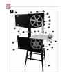
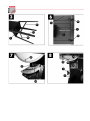
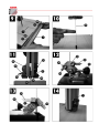
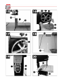
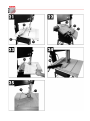
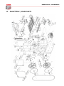
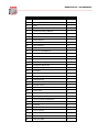
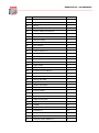
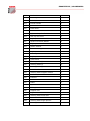
DE BEDIENUNGSANLEITUNG DE HOLZBANDSÄGE EN EN USER MANUAL WOOD BANDSAW HBS 300J Ausgabe: 11.02.2014 – Revision 02 DEUTSCH 1. AUFBAU DER (FIG 1 UND 2) MASCHINE 1) 2) 3) 4) 5) 6) 7) 8) 9) 11) 12) 13) 14) 15) 16) 17) 18) 19) 20) 21) 22) 23) 24) 25) Ein/Aus Schalter Halterung Laufgummi Handrad Bodenplatte Absauganschluss unteres Bandsägelaufrad obere Bandsägelaufrad Festziehrad Obere Sägebandführung Türe Türverschluss Fixierschraube Arbeitstisch Winkelskala Tischneigung Tischeinlage Winkelfixierhebel für Arbeitstisch Einstellhebel für Sägebandführung Fixierung d. Sägebandführung Stellfüße Einstellrad für oberes Laufrad Parallelanschlag Maschinenkörper Sägeband 2. LIEFERUMFANG Bandsäge Bandsägeband Arbeitstisch Schiebestock Parallelanschlag Unterbau mit Stellfüße 3. SICHERHEITSHINWEISE o o o o o ACHTUNG! Jedesmal, wenn Sie mit einem elektrisch betriebenen Sägegerät arbeiten, ist höchste Vorsicht geboten! Es besteht Gefahr von Stromschlag, Feuer, Schnittverletzung; Die Anleitung ist Teil der Maschine. Geben Sie diese Anleitung an jede Person, die diese Maschine benutzt. Sorgen Sie für eine sichere Arbeitsumgebung! Kein Betrieb bei Regen oder in feuchter Umgebung! Halten Sie die Arbeitsumgebung sauber! Sorgen Sie für gute Lichtverhältnisse! Kein Betrieb in der Nähe von explosions- oder brandgefährlichen Stoffen. Minimieren Sie Störquellen, die Ihre Konzentration stören könnten. Vermeiden Sie Körperkontakt mit geerdeten Bauteilen! Betrieb der Maschine nur durch Fachpersonal ab 18 Jahren. Unbefugten, insbesondere Kindern, ist der Zugang zur Maschine verboten. Überlasten Sie Ihre Maschine nicht für Tätigkeiten, für die eine größere Maschine vorgesehen wäre! Brennholz schneiden ist verboten! Benutzen Sie für jede Tätigkeit das bestmöglich geeignete Werkzeug. Arbeiten Sie stets konzentriert! Kleiden Sie sich den Arbeitsvorschriften entsprechend! Tragen Sie keine langen Haare, keine abstehende Kleidung, keinen Schmuck etc. Diese könnten von bewegenden Maschinenteilen erfasst werden und dem Benutzer schwere Verletzungen zufügen! Tragen Sie eine Schutzbrille sowie Gehörschutz. Arbeiten Sie in gut durchlüfteten Räumen! Vorsicht – manche Holzwerkstoffe beinhalten gesundheitsschädigende chemische Lösungsmittel etc. In diesem Falle ist zusätzlich eine Atemschutzmaske zu verwenden. Der Anschluss der Maschine an eine Absauganlage mit Mindestabsaugleistung von 20m/sec ist alleine aus gesundheitlichen Gründen verpflichtend. Prüfen Sie Ein/Aus/NOTAUS Schalter regelmäßig auf Funktionstüchtigkeit. Prüfen Sie regelmäßig das Elektrokabel auf Beschädigungen. GEFAHR! RÜCKSCHLAGGEFAHR! Achten Sie stets auf einen sicheren Stand. halten Sie Ihre Hände vom Bandsägeblatt fern! Seien Sie auf einen möglichen Rückschlag vorbereitet! DEUTSCH Benutzen Sie bei schmalen Schnitten IMMER den Schiebestock zur Werkstückführung! 4. BEDIENHINWEISE Die Bandsäge HBS 300J ist für das Schneiden von Holzwerkstoffen im privaten Heimwerkerbereich vorgesehen. Das Schneiden von Brennholz ist verboten. Runde Werkstücke dürfen nur unter Verwendung von zusätzlichen Hilfsmitteln zur Werkstückfixierung bearbeitet werden. Lesen Sie diese Anleitung aufmerksam durch! Holzmann Maschinen haftet nicht für Schäden, die durch unsachgemäße Verwendung bzw. durch eigenmächtige Änderungen der Maschine entstanden sind! Auch bei sachgemäßer Verwendung bestehen Restrisiken: Hörschaden bei mangelhaftem Gehörschutz. Gefährdung der Atemwege bei giftigem Holzstaub. Schwere Verletzungen bei Kontakt mit dem Bandsägeblatt Verletzung durch fliegende Werkstückteile, -splitter. Quetschung der Finger. Verletzungsgefahr bei Rückschlag. Bei erstem Einschalten prüfen Sie die Laufrichtung des Motors (bei 400V). Sollte der Motor in die falsche Richtung laufen, ist durch einen Elektrofachmann die Phase zu wenden. Lassen Sie den korrekten Anschluss Ihrer Maschine durch einen Elektrofachmann prüfen. Der Sägebandschutz (10) sollte 3mm über der Höhe des zu bearbeitenden Werkstückes stehen. Lange Werkstücke sind mit einem Rollbock zu sichern. Vergewissern Sie sich, dass das gewählte Sageblatt für Ihren Holzwerkstoff und für die gewünschte Schnittgenauigkeit geeignet ist! Fragen Sie beim Kauf Ihren Fachhändler. Defekte Bandsägeblätter sind sofort zu ersetzen! Stumpfe Bandsägeblätter sind zu schärfen! Beachten Sie unbedingt die gültigen Unfallverhütungs- und Arbeitsvorschriften Ihres Landes sowie die Information in dieser Anleitung. Schneiden Sie NIE Werkstücke, welche nicht 100% sicherbar sind. Ziehen Sie vor jeglichen Wartungs- oder Reinigungsarbeiten den Netzstecker! 5. TECHNISCHE 300J DATEN HBS Spannung 230V/ ~ 50Hz Leistung 750W Leerlauf no 1400 min-1 Bandsägebandlänge 2240mm Bandsägebandbreite 6-18mm Bandgeschwindigkeit 360/720 m/min Schnitthöhe 90° 170mm Schnitthöhe 45° 70mm Tischgröße 500 x 400mm Schwenkbereich Tisch 90° - 45° Max. Werkstückgröße 600 x 600mm Gewicht 83kg LÄRMEMISSIONSWERTE LPA LWA Schalldruck Schallleistung 102,3db(A) 6. VOR INBETRIEBNAHME Vergewissern Sie sich, dass die Maschine stabil steht. Vor Inbetriebnahme überprüfen Sie, dass alle Werkzeuge vom Arbeitstisch entfernt sind und alle Fixierhebel, schrauben, -handräder angezogen sind. Prüfen Sie das Werkstück vor der Bearbeitung auf Fremdkörper! 92,7db(A) DEUTSCH 7. 7.1 MONTAGE Untergestell montieren Befestigen Sie zuerst die Stellfüße (21) locker zur Grundplatte (5) der Maschine mit jeweils 2 Schrauben pro Fuß. Schrauben Sie die 2 langen Querstreben (41) und die 2 kurzen Querstreben (42) locker an die Stellfüße an (Fig. 3). Stecken Sie die Gummifüße auf die Stellfüße (21). Stellen Sie die Maschine auf das Untergestell (auf die Grundplatte). Richten Sie das Untergestell (2. Person erforderlich) aus, sodass die Maschine zu allen Richtungen eben ist. Fixieren Sie nun alle Schrauben des Untergestells. Montieren Sie die Halterung (29) des Schiebestockes (28), folgendermaßen: Schrauben Sie die Fixiermutter auf den Bolzen und schrauben Sie dann den Bolzen an. 7.2 Arbeitstisch montieren Lösen Sie die Fixierhebel (45) an der Unterseite des Tisches (15) und entfernen Sie die Halterung (2) vom Tisch. Führen Sie das Bandsägeblatt durch den Schlitz (a) in den Arbeitstisch und platzieren Sie den Arbeitstisch so auf der Tischaufhängung, dass die Fixierschraube (47) durch die Halterung (48). Schrauben Sie den Arbeitstisch mit der Flügelmutter (18) fest. Platzieren Sie die Halterung (2) auf dem Tisch (15), sodass die Schraubenköpfe (50) in die Führungsschlitze (51) laufen. Prüfen Sie, dass das Bandsägeband (25) frei läuft und den Tisch nicht berührt. 7.3 Bandsägeband spannen (Fig. 10) ACHTUNG! Lösen Sie die Spannung vom Bandsägeband, wenn die Maschine längere Zeit nicht benutzt wird. Vergessen Sie NIE, vor Inbetriebnahme das Band erneut zu spannen! 7.4 Drehen Sie das Festziehrad (9) im Uhrzeigersinn, um das Bandsägeband (25) zu spannen. Die korrekte Bandspannung kann folgendermaßen ermittelt werden: Drücken Sie in der Mitte mit einem Finger seitlich gegen das Bandsägeband, das Band sollte max. 1-2mm nachgeben. ACHTUNG! Das Bandsägeband reißt wenn es zu stark gespannt ist! Verletzungsgefahr! Wenn die Bandspannung zu niedrig ist, dreht zwar das Bandsägelaufrad (7) aber das Band läuft nicht. Bandsägeband einstellen ACHTUNG! Das Bandsägeband muss vor der Einstellung bereits korrekt aufgespannt sein. Öffnen Sie die Türverschlüsse (13) und öffnen Sie die Abdeckung (12). Drehen Sie das obere Bandsägelaufrad (8) langsam im Uhrzeigersinn. Das Bandsägeband (25) sollte zentral auf dem Laufrad (8) laufen. Wenn dies nicht der Fall ist, muss der Neigungswinkel des oberen Laufrades (8) angepasst werden. Wenn das Bandsägeband in Richtung hintere Seite des Laufrades wegläuft, muss das Einstellrad (22) im Uhrzeigersinn gedreht werden. Läuft es zur vorderen Seite des Laufrades hin weg, muss das Einstellrad (22) gegen den Uhrzeigersinn gedreht werden. Prüfen Sie nach jeder Einstellung die Änderung, indem Sie das Laufrad mehrere Male komplett drehen. Wenn Sie die Position des oberen Laufrades gefunden haben, bei dem das Bandsägeband in der Mitte zentriert läuft, drehen Sie bitte das obere Laufrad einige Male, sodass das Band auch am unteren Laufrad in der Mitte aufliegt. Wenn Sie das Bandsägeband erfolgreich eingestellt haben, schließen Sie die Türe (12) und verschließen diese mit dem Türverschluss. Fixieren Sie das Einstellrad (22) mit der Fixierschraube (14) gegen unbeabsichtigtes Verdrehen. DEUTSCH 7.5 Sägebandführung einstellen (Fig. 11 +13) Jedesmal, wenn Sie das Bandsägeband wechseln, müssen Sie die Lauflager (30-31) sowie die Führungen (28+29) neu einrichten! 7.5.1 oberes Lauflager einstellen Lösen Sie die Schraube (33). Bewegen Sie das Lauflager (30) so, dass es fast das Bandsägeband berührt. Die Distanz sollte ca. 0,5mm betragen Ziehen Sie die Schraube (33) wieder fest. 7.5.2 unteres Lauflager einstellen Demontieren Sie den Arbeitstisch (15). Stellen Sie das untere Lauflager (31) in der selben Art und Weise ein wie das obere Lauflager (30) zuvor. 7.5.3 obere Führungen (28) einstellen Lösen Sie die Schraube (35). Bewegen Sie die Halterung (36) der Führung (28) so, dass ein Spalt von ca. 1mm zu Bandsägeblatt entsteht. Fixieren Sie wieder die Schraube (35). Achtung! Das Bandsägeband wird zerstört, wenn die Zähne des Bandes die Führung berühren. Lösen Sie die Schraube (37). Bewegen Sie die Führungen (28) so, dass ein Spalt von ca. 0,5mm zw. Führung und Bandsägeband ist. Ziehen Sie die Schraube (37) fest. Drehen Sie das obere Laufrad (8) einige Male im Uhrzeigersinn, um die Einstellungen zu überprüfen. 7.5.4 untere Führung (29) einstellen Demontieren Sie den Arbeitstisch (15) (siehe 7.2). Lösen Sie die Schraube (40). Bewegen Sie die Halterung der Führungen (29) so, dass ein Spalt von ca. 1mm zu Bandsägeblatt ist. Ziehen Sie die Schraube (40) wieder fest. Achtung! Das Bandsägeblatt wird zerstört wenn die Zähne die Führung berühren! Entfernen Sie die Schrauben (38). Bringen Sie die Führungen (29) Richtung Bandsägeblatt, sodass ein Spalt von ca. 0,5mm entsteht zw. Führung (29) und Bandsägeblatt (25). Ziehen Sie die Schrauben (38) wieder fest. Drehen Sie das untere Laufrad (7) einige Male im Uhrzeigersinn, um die Einstellung zu überprüfen. 7.6 Obere Sägebandführung einstellen Lösen Sie die Fixierung der Sägebandführung (20). Betätigen Sie den Einstellhebel (19) der Sägebandführung, und bringen Sie die Führung so nahe als möglich zum Werkstück (Spalt sollte ca. 3mm betragen). Fixierung (20) wieder festziehen. 7.7 Arbeitstisch (15) einstellen auf 90° (Fig. 8 und 15) Bewegen Sie die obere Sägebandführung (11) in die oberste Position. Lösen Sie den Winkelfixierhebel für den Arbeitstisch (18). Platzieren Sie ein Winkelmessgerät (d) auf den Arbeitstisch (15) und legen Sie es am Bandsägeband (25) an. Schwenken Sie den Arbeitstisch (15) sodass der Winkel zwischen Tisch und Bandsägeband genau 90° ausmacht! Ziehen Sie den Winkelfixierhebel (18) wieder an. Lösen Sie die Schraube (52) der Winkelanzeige, und richten Sie die Spitze der Winkelanzeige so aus, dass diese exakt auf die 0° Markierung zeigt! Schraube (52) wieder festziehen. 7.8 Wahl des Bandsägebandes Das mitgelieferte Bandsägeband ist so gewählt, dass es für vielfältige Aufgaben verwendbar ist. Wenn Sie ein Bandsägeband auswählen, beachten Sie folgende Punkte: Zum Schneiden von kleinen Radien verwenden Sie eher schmale Bandsägeblätter DEUTSCH 7.9 Für gerade Schnitte sowie Schnitte in Massivholz sind breite Bandsägeblätter zu verwenden, Das Bandsägeblatt hat nämlich die Tendenz, bei Massivholz der Faserung zu folgen. Diesen Effekt können Sie mit der Verwendung von breiten Blättern reduzieren. Bandsägeblätter mit feiner Zahnung liefern ein saubereres Schnittbild als grobgezahnte Blätter, jedoch auf Kosten der durchschnittlichen Schnittgeschwindigkeit. Bandsägeblattwechsel ACHTUNG! Bei Bandsägeblattwechsel immer Handschuhe verwenden! Schnittgefahr! Bringen Sie die Sägeblattführung 11) in ca. mittlere Position zw. Tisch und obere Maschinenkörper (24). Lösen Sie den Türverschluss (13) und öffnen Sie die Türe (12). Entfernen Sie die Halterung (2). Drehen Sie das Festziehrad (9) gegen den Uhrzeigersinn um die Bandsägeblattspannung zu lösen. Entfernen Sie das Bandsägeblatt (25), indem Sie es von den Laufrädern (7 +8) ziehen und aus dem Tisch ziehen. Legen Sie das neue Band ein, achten Sie dabei, dass es zentral auf den Laufrädern aufliegt. Die Zähne des Blattes müssen nach unten Richtung Tisch zeigen! Spannen Sie das Bandsägeband. Schließen Sie die Türe (12) und verschließen Sie sie. Nach erfolgtem Bandsägebandwechsel drehen Sie das Bandsägeblatt einige Male, falls nötig sind die Punkte 7.4 und 7.5 durchzuführen! 7.10 Laufradgummierung wechseln (Fig. 17) Durch den Betrieb nützen sich die Laufradgummierungen der Holzbandsäge ab. Dies ist ganz normal. Sobald die Gummierungen abgenützt sind, müssen sie ersetzt werden. Öffnen Sie die Türe (12). Entfernen Sie das Bandsägeband (25). Lösen Sie die Kante des Gummirades (3) mit einem kleinen Schlitzschrau- benzieher (f), lösen und entfernen Sie das alte Gummirad. Montieren Sie das neue Gummirad (Ersatzteil bei Fachhändler zu bestellen), montieren Sie das Bandsägeblatt (25) und schließen Sie die Türe (12). 7.11 Tischeinlage wechseln (Fig. 18) Um das Verletzungsrisiko zu minimieren, ist rund um das Bandsägeblatt eine Tischeinlage (17) vorgesehen. Wechseln Sie diese, wenn sie beschädigt oder abgenutzt ist. Legen Sie den Arbeitstisch (15) frei, sodass Sie freien Zugang zur Tischeinlage 817) haben. Ziehen Sie nun die Tischeinlage (17) heraus. Führen Sie die Ersatzeinlage ein, und bringen Sie den Arbeitstisch wieder in betriebsbereiten Zustand. 7.12 Absauganschluss Die HBS 300J ist zum Betrieb mit einer Absauganlage vorgesehen. Der Absauganschluss (6) hat einen Durchmesser von 100mm. 7.13 Bandsägegeschwindigkeit len einstel- Die Holzbandsäge kann in zwei Geschwindigkeiten betrieben werden. Um die Geschwindigkeit zu ändern, gehen Sie bitte folgendermaßen vor: Lösen Sie den Antriebsriemen (54) indem Sie das Handrad (4) gegen den Uhrzeigersinn drehen. Bringen Sie den Riemen in die gewünschte Stellung auf der Riemenscheibe (55) und dem unteren Laufrad (7). Die Bandgeschwindigkeit ist an der Innenseite der unteren Türe angebracht. Spannen Sie den Antriebsriemen (54) indem Sie das Handrad (4) im Uhrzeigersinn drehen. WICHTIG: Antriebsriemen dürfen nicht zu stark gespannt werden. DEUTSCH 8. BETRIEB 8.1 EIN/AUS Schalter (Fig. 19) Um die Holzbandsäge einzuschalten, drücken Sie den grünen Knopf (g). Um die Holzbandsäge auszuschalten, drücken Sie den roten Knopf (h). Ihre Holzbandsäge hat einen Unterspannungsschalter. Nach einem Stromausfall z.B. müssen Sie den Schalter reaktivieren 8.2 Parallelanschlag (Fig. 20/21) Der Parallelanschlag dient als seitliche Werkstückführung. Platzieren Sie den Parallelanschlag (23) auf die Halterung (2). Zum Fixieren drücken Sie den Fixierhebel (27) herunter. Die Halterung (2) kann unterschiedlich für dünne Werkstücke verwendet werden (Fig. 20) oder auch für dickere Werkstücke (Fig. 21). 8.3 Gehrungsschnitte (Fig. 8/22) Lösen Sie den Winkelfixierhebel (18) für den Arbeitstisch. Schwenken Sie den Arbeitstisch (15) nach vorne bis der gewünschte Winkel an der Skala (16) angezeigt wird. Fixieren Sie den Winkelfixierhebel (18). Wenn Sie Gehrungsschnitte machen, muss der Parallelanschlag an der Außenseite des Tisches montiert sein, so liegt das Werkstück automatisch auf dem Parallelanschlag auf. 9. BETRIEBSHINWEISE WICHTIG! Nach jeder neuen Einstellung empfehlen wir Ihnen, dass Sie einen Probeschnitt machen, um die gewählte Einstellung zu prüfen. Für alle Schnittoperationen gilt: Sägebandführung auf ca. 3mm an das Werkstück einstellen (siehe 7.6). Führen Sie das Werkstück stets mit zwei Händen. Sollte zu einer Seite hin der Abstand zwischen Werkstückkante 9.1 und Schnittlinie unter 12 cm liegen, ist für diese Seite statt der Hand der Schiebestock zu verwenden. Führen Sie das Werkstück gleichmäßig zu, sodass das Bandsägeblatt problemlos durchsägen kann. Verwenden Sie stets den Parallelanschlag als seitliche Führung. Wenn irgendwie möglich, sollte eine Schnitt als ganzes durchgeführt werden! Müssen Sie jedoch das Werkstück entfernen, schalten sie VORHER die Maschine aus und warten bis das Bandsägeblatt komplett zum Stillstand kommt. Das Werkstück sollte immer auf der breiteren Seite geführt werden während der Schnittoperation Längsschnitte (Fig. 20) Längsschnitte sind ablängen von Holz, mehrheitlich entlang der Faserung. Platzieren Sie den Parallelanschlag (23) links des Bandsägeblattes. Passen Sie die Sägebandführung (11) auf die Werkstückhöhe + 3mm an. Schalten Sie die Holzbandsäge ein. Drücken Sie die Kante des Werkstückes gegen den Parallelanschlag sowie auf den Arbeitstisch und führen Sie das Werkstück kontinuierlich zu. ACHTUNG: Lange Werkstücke müssen hinten mit einem Rollbock abgestützt werden. 9.2 Freie und gebogene Schnitte (Fig. 25) Der einzigartige Vorteil einer Bandsäge besteht in der Möglichkeit, mühelos gebogene geschwungene, runde Schnitte zu vollführen. Senken Sie die Sägebandführung (11) auf Werkstückhöhe +3mm) Schalten Sie die Säge ein. Halten Sie das Werkstück sicher auf dem Arbeitstisch (15) und führen sie das Werkstück der Schnittlinie folgend dem Bandsägeblatt (25) zu. Freihandschnitte sollten stets langsam gemacht werden! Überschüssige Kanten können Sie vor dem Schnitt auf Schnittlinie im Vorfeld entfernen. DEUTSCH 10. WARTUNG Wichtig! Vor jeglichen Wartungs- und Instandhaltungsarbeiten ziehen Sie als erstes den Netzstecker! Befreien Sie die Maschine regelmäßig nach der Arbeit von Holzstaub und Holzresten. Verwenden Sie nie Chemische Stoffe zur Reinigung. 11. ERSATZTEILBESTELLUNG Vor jeder Ersatzteilbestellung halten Sie bitte folgende Informationen bereit. Modell/Type der Maschine Seriennummer der Maschine Gekauft bei wem, wann? Nummer(n) der Ersatzteile, die benötigt werden. ENGLISH 1. LAYOUT 1) 2) 3) 4) 5) 6) 7) 8) 9) 11) 12) 13) 14) 15) 16) 17) 18) 19) 20) 21) 22) 23) 24) 25) On/Off Switch Chain bar Rubber tires Hand wheel Base plate Dust extraction connector Lower blade pulley Upper blade pulley Tightening screw Upper blade guide Side cover Cover fastener Retaining screw for upper blade pulley Machine table Dial scale for tilt angle Table insert Fixing handles for table Adjustable handle for blade guide Fixing handle for blade guide Legs Setting screw for upper blade pulley Parallel stop Machine frame Blade 2. ITEMS SUPPLIED Bandsaw Machine table Push stick Parallel stop Base frame Blade 3. PROPER USE The bandsaw is intended for the slitting and cross-cutting of timber or wood-like workpieces. Round materials may only be cut with suitable holding devices. The machine is to be used only for its prescribed purpose. Any other use is deemed to be a case of misuse. The user/operator and not the manufacturer will be held liable for damage and/or inju- ries of any kind that result from such misuse. The machine is to be operated only with suitable saw blades. To use the machine properly you must also observe the safety regulations, the assembly instructions and the operating instructions to be found in this manual. All persons who use and service the machine have to be acquainted with this manual and must be informed about the machine`s potential hazard. It is also imperative to observe the accident prevention regulations in force in your area. The same applies for the general rules of health and safety at work. HOLZMANN will not be liable for any changes made to the machine nor for any damage resulting from such changes. Even when the machine is used as prescribed it is still impossible to eliminate certain residual risk factors. The following hazards may arise in connection with the machine´s construction and design: Damage to hearing if ear-muffs are not used as necessary. Harmful emissions of wood dust when used in closed rooms. Contact with the blade in the uncovered cutting zone. Injuries (cuts) when changing the blade. Injury from catapulted workpieces or parts of workpieces. Crushed fingers. Kickback. Tilting of the workpiece due to inadequate support. Touching the blade. Catapulting of pieces of timber and workpieces. 4. IMPORTANT INFORMATION SAFETY INFORMATION CAUTION! Whenever you use electric tools it is imperative to take basic safety precautions in order to reduce the risk of fire, electric shock and personal injury. Essential safety precautions include: Keep your work area tidy! An untidy work area may cause accidents. ENGLISH Check the working conditions. Do not expose your bandsaw to rain. Never use it in damp or wet locations. Make sure there is good lighting. Do not use the bandsaw near flammable liquids or gases. Guard against electric shock! Avoid body contact with earthed components. Keep other persons away. Do not allow other persons, particularly children, to touch the machine or the cable. Keep them away from your work area. Store tools in a safe place. When tools are not in use they should be stored in a dry, locked room out of children`s reach. Do not overload your machine. Your bandsaw works better and safer when used within their quoted capacity range. Use a machine with insufficient power for a job at hand. Never use your bandsaw for on jobs for which it was not untended. Wear suitable work clothes! Do not wear loose clothing or jewellery as they might get caught in moving parts. Wear a hair net if you have long hair. Use personal safety equipment: earmuffs, safety goggles, dust mask when working on dusty jobs. Connect the machine to a vacuum extraction system! Do not use the cable for purposes for which it is not designed. Avoid abnormal working postures! Make sure you stand squarely and keep balance at all times. Always pull out the power plug: When the machine is not being used, plug it out. Remove adjusting keys, wrenches and other tools from the working table after use. Always stay focused when working. Reduce distortion sources in your working environment. Check the ON/OFF Switch periodically. Have repairs carried out only by a qualified electrician. Have your power connection checked by a qualified electrician. Wear safety gloves whenever you carry out any maintenance work on the blade. In the case of mitre cuts the parallel guide must be placed at the lower place of the working table to hold the workpiece. A dust collecting system with a minimum air velocity of 20m/min shall be connected to the bandsaw. Give this operation manual to every person who works with the machine. DO NOT USE THIS SAW TO CUT FIREWOOD. The machine is equipped with a safety switch to prevent it being switched on again accidentally after a power failure. Never dismantle the machine`s safety devices or render them infunctional. Let unreadable safety stickers be replaced immediately. Never cut workpieces that are too small to be guided securely by your hand or pushstick. Never remove loose splinters, chips or jammed pieces of wood when the saw blade is running. It is imperative to observe the accident prevention regulations in force in your country as well as all other generally recognized rules of safety. Position the blade guard so that it is approx. 3mm above the material you want to saw. Secure long workpieces against falling off at the end of the cut with a roller table. Make sure the blade guard is in its lowest position when the machine is being transported. Blades that are deformed or damaged have to be replaced immediately. Worn table inserts have to be replaced immediately. Never start the machine when the door protecting the blade is open. Do not touch the blade until it has come to a complete stop. IMPORTANT: THIS BANDSAW IS INTENDED ONLY FOR HOME AND DOIT-YOURSELF HOBBY USE. THE MACHINE IS NOT DESIGNED FOR PROFESSIONAL USE. ENGLISH 5. TECHNICAL DATA HBS 300J 230V/~ 50Hz Power 750W Idle run speed no 1400 min-1 Blade length 2240mm Blade width 6-18mm Blade speed 360/720 m/min Cutting height 90° 170mm Cutting height 45° 70mm Table size 500 x 400mm Tilting range 90° - 45° Max. workpiece size 600 x 600mm weight 83kg Make sure the machine stands securely, i.e. bolt it to a workbench or solid base. Fixing holes are provided in the base plate for this purpose. The saw table must be correctly assembled. All covers and safety devices have to be properly fitted before the machine is switched on. It must be possible for the blade to run freely. When working with wood that has been processed before, watch out for foreign bodies such as nails or screws etc, Before you actuate the On/off switch, make sure that the saw blade is correctly fitted and that the machine`s moving parts run smoothly. Check that the voltage on the rating plate is the same as your supply voltage before you connect to the power supply. First attach the legs (21) loosely to the base plate (5) of the machine using 2 screws for each leg. Use the round head M8x12 screws to do so. Screw the 2 long struts (41) and the 2 short struts (42) loosely to the legs (21). The doubled-over part of the struts must be at the top. Attach the rubber feet to the legs (21). Place the machine onto the legs Align the entire base frame and tighten all screws. Fasten the holder (29) for the push stock (28) as follows: Screw the lock nut onto the bolt (29) and then screw this into the housing until the push stick (28) can be hung up. 92,7dB(A) 102,3dB(A) BEFORE MACHINE Assembly of the sub-frame and wheels (Fig. 3-5/27) 6. 7.1 Nose emission values: STARTING ASSEMBLY CAUTION! Pull out the power plug before carrying out any maintenance, assembly, resetting work on the machine! Voltage LPA sound pressure level LWA sound power level 7. THE 7.2 Assembling the saw table (Figures 6-9) Slacken the wing nuts (45) on the underside of the saw table (15) and remove the chain bar (2) from the saw table. Lead the blade through the slot (a) in the machine table and place the machine table on the table guide so that the clamping screw (47) fits through the mounting (48). Screw the saw table tight with the wing nut (18). Place the chain bar (2) onto the saw table (15) so that the screw heads (50) slide into the guide slots (51). Check that the blade (25) runs freely and does not touch the saw blade. To remove the saw blade guard, proceed in reverse order. ENGLISH 7.3 Tensioning the blade CAUTION! Remove the tension from the blade if the bandsaw is not going to be used for some time. Be sure to retension the blade before you start the machine. Turn the tightening screw (9) for tensioning the blade (25) in a clockwise direction. The correct blade tension can be checked by applying pressure to the side of the blade with your finger, somewhere in the middle between the two blade pulleys (7+8). You should only be able to bend the blade (25) very slightly (approx. 1-2mm). CAUTION! The blade may break if the tension is too high. BEWARE IF INJURY! If the tension is too low, the powered blade pulley (7) will spin while the blade does not move. 7.4 Adjusting the blade Undo the fasteners (13) and open the side cover (12). Turn the upper blade pulley (8) slowly in a clockwise direction. The blade (25) should run centrally on the blade pulley (8). If it does not, the angle at which the upper blade pulley (8) tilts must be adjusted. If the blade (25) runs more towards the rear of the blade pulley (8), i.e. towards the machine housing (24), the setting screw (22) must be turned in an anticlockwise direction. Then turn the blade pulley (8) slowly with the other hand to check the position of the blade. If the blade (25) runs towards the front edge of the belt pulley (8), the setting screw (22) must be turned in a clockwise direction. After adjusting the upper blade pulley (8), check the position of the blade (25) on the lower blade pulley (7). Again, the blade (25) should run in the middle of the blade pulley (7). When adjusting the upper blade pulley you have to turn it several times until the adjustment has an effect on the position of the blade on the lower blade pulley. When adjustment has been completed, close the side cover (12) again and secure it with the fasteners (13). 7.5 Adjusting the blade guide (Fig. 1113) Whenever you change the blade you must reset both the support bearings (30+31) and the guide pins (28+29). 7.5.1 Upper support bearing (Fig. 11) Undo the screw (33). Move the support bearing (30) s that it is almost touching the blade (25). There should be a gap of approx. 0,5mm. Re-tighten the screw. 7.5.2 Setting the lower support bearing (31) Disassemble the saw blade (15). Adjust in the same way that the upper support bearing was adjusted. The blade (25) is only supported by the support bearings (30+31) during cutting. During idle run the blade should not touch the ball bearings. 7.5.3 Setting the upper guide bearings (Figure 11) Undo the screw (35). Move the mount (36) of the guide bearings (28) so that there is a gap of approx. 1mm between the front edge of the guide bearings (28) and the gullet of the blade in front. Re-tighten the screw (35) CAUTION! The blade will be rendered useless if the teeth touch the guide bearings while the blade is running. Undo the screws (37) Move the two guide bearings (28) towards the blade so that there is a gap of approx. 0,5mm between the guide bearings (28) and the blade (25). Re-tighten the screws (37). ENGLISH Turn the upper blade pulley (8) several times in a clockwise direction. Check the setting of the guide bearings (28) again and re-adjust If necessary. Tilt the table (15) by turning it so that the angle between it and the blade (25) is precisely 90°. Re-tighten the fixing handles (18). Undo the screw (52) of the pointer of the dial scale (16), set the pointer to exactly 0° and tighten the screw (52) again. 7.8 Blade selection 7.5.4 Setting the lower guide bearings (29) (Fig. 12/13) Disassemble the saw table (15) (see 7.2) Undo the screw (40) Move the mount of the guide pins (29) so that there is a gap of approx. 1mm between the front edge of the pins (29) and the gullet of the blade in front. Re-tighten the screw (40). CAUTION! The blade will be rendered useless if the teeth touch the guide pins while the blade is running. Undo the screws (38). Move the guide pins (29) towards the blade so that there is a gap of max. 0,5mm between the guide pins (29) and the blade (25). (The blade must not jam). Re-tighten the Allen screws (38). Turn the lower blade pulley (7) several times in a clockwise direction. Check the setting of the guide pins (29) again and re-adjust if necessary. 7.6 Adjusting the upper blade guide (11) (Fig. 2/14) Undo the fixing handle (20). Turn the adjustment wheel (19) to lower the blade guide (11) as close as possible to the workpiece to be cut (the gap should be approx. 2-3mm). Re-tighten the fixing handle (20). Check the setting before each cut and re-adjust if necessary. 7.7 Adjusting the saw table (15) to 90° (8/15) Move the upper blade guide 811) to the top. Undo the fixing handles (18). Set the angle (d) between the blade (25) and the table (15). The blade supplied with the bandsaw is designed for all-purpose use. When you select a blade you should have regard to the following criteria: Use a narrow blade to cut tighter radii than you can with a wider blade. Wide blades are used to saw straight cuts. This is particularly important in cutting wood because the blade has a tendency to follow the grain of the wood and thereby deviate easily from the cutting line. Finely toothed blades provide smoother cuts but are slower than coarse blades. IMPORTANT: Never use warped or lacerated blades! 7.9 Replacing the blade (Figure 16) Move the blade guide (11) into a position approximately half way between the table (15) and the machine frame (24). Undo the fasteners (13) and open the side cover (12). Remove the chain bar (2). Turn the tightening screw (9) anticlockwise to remove the tension from the blade (25). Remove the blade (25) from the blade pulleys (7,8) and take out through the slot in the table (15). Fit the new blade (25), aligned centrally on the blade pulleys (7,8). The teeth of the blade (25) must point downwards in the direction of the table. Tension the blade (25) (see 7.2) Close the side cover (12) again. Mount the web panel (4) again. ENGLISH 7.10 Changing the rubber tires on the blade pulleys (Fig. 17) After a certain time the rubber tires (3) on the blade pulleys (7,8) will get worn by the sharp teeth of the blades and must be replaced. Open the side cover (12). Remove the blade (25) (see 7.7) Lift the edge of the tire (3) with a small screwdriver (f) and remove it from the blade pulley (8). Repeat for the lower blade pulley (7). Fit the new rubber tire (3), mount the blade (25) and close the side cover (12) again. 8. OPERATION 8.1 ON/OFF switch (Fig. 19) To turn the saw on, press the green button (g). To turn the saw off again, press the red button (h). Your bandsaw has a switch with undervoltage release. After a power failure you must reactivate the switch 8.2 Parallel stop (Fig. 20/21) To prevent increased likelihood of injury the table insert (17) should be changed whenever it is worn or damaged. Dismantle the saw table (15) (see 7.2). Push out the worn table insert (17). Fit the replacement table insert by following the above in reverse. The parallel stop is used as a guide in slitting. Place the parallel stop (23) onto the chain bar (2) on the left or right and set the desired dimension. Clamp the parallel stop in the desired position by pressing the clamping lever (27) The chain bar can be used for thinner workpieces as shown in Figure 20 and for thicker workpieces as shown in Figure 21. 7.12 8.3 7.11 Changing the table insert (Fig. 18) Extractor port The bandsaw is equipped with an 100mm extractor socket (6) for extracting sawdust and chips. 7.13 Adjusting the blade speed (Fig. 28) The bandsaw can be operated at two blade speeds. To change the position proceed as follows: Slacken the drive belt (54) by turning the hand wheel (4) in an anticlockwise direction. Move the belt to the desired position on the belt pulley (55) and the lower blade pulley (7). The blade speeds are indicated on the inside of the side cover. Tension the drive belt (54) again by turning the hand wheel (4) in a clockwise direction. Important: Drive belts must not be tensioned too much! Angular cuts (Figure 8/22) To enable you to perform angular cuts parallel to the blade (25), the table (15) can be tilted forwards between 0° -45°. Undo the fixing handle (18). Tilt the saw table (15) forward until required angle value has been set on the man scale (16). Re-tighten the fixing handle (18). Important: When the table (15) is tilted, place the parallel stop (23) to the right of the blade (25) looking in the direction in which you are working, on the side pointing downwards. (provided the workpiece is wide enough) in order to stop the workpiece from slipping off. ENGLISH 9. OPERATION ADVICES Important! After every new adjustment we recommend you to make a trial cut in order to check the new settings. For all cutting operations it is important to position the blade guide (11) as close as possible to the workpiece. Always guide the workpiece with both hands, holding it flat on the table (15) in order to prevent the blade (25) from jamming. Feed the workpiece at a uniform speed that enables the blade to cut through the material without difficulty and without blocking. Always aim at making a complete cut in one pass rather than in a stop-and-go operation requiring the workpiece to be withdrawn. If you have to withdraw the workpiece, switch off the bandsaw first and wait for the blade (25) to stop before freeing the workpiece. The workpiece must always be guided by the longer side during cutting. Important! When handling narrower workpieces, it is essential to use a push stick. The push stick (28) must always be kept close at hand at then hook(29) provided for that purpose on the side of the saw (Fig. 27). 9.1 Longitudinal cuts Longitudinal cutting (also known as slitting) is when you use the saw to cut along the grain of the wood. Place the parallel stop (23) to the left of the blade (25), as far as possible, for the width required. Lower the blade guide (11) down to the workpiece. Switch the saw on. Press the edge of the workpiece with your right hand to hold it securely against the parallel stop (23) and flat on the table (15). Guide the workpiece along the parallel stop (23) and through the blade (25) at a uniform speed. Important: Long workpieces must be secured against falling off the table at the end of the cut- 9.2 Freehanded cuts (Figure 25) One of the most outstanding features of a bandsaw is the ease with which it allows you to make curved cuts and radii. Lower the blade guide (11) down to the workpiece. Switch on the saw. Hold the workpiece securely on the table (15) and guide slowly through the blade (25). Freehanded cuts should be made at low feed speed so that you can guide the blade (25) along the required line. It often pays to first cut off surplus curves and corners up to about 6mm from the cutting line. In the case of curves which are too tight for the blade to cut correctly, it can help to make a series of close-lying cuts at right angles to the curved line. When you saw the radius the material simply will drop off. 10. MAINTENANCE Important! Pull out the power plug first. Remove the dust and dirt regularly from the machine. Cleaning is best carried out with a fine brush or a cloth. Never use caustic agents to clean plastic parts. 11. ORDERING SPARE PARTS Please orders provide the following information on all for spare parts: Model/type of the machine Date of acquisition Serial number of the machine Spare part(s) marked on exploded drawing Required spare part numbers listed additionally. DEUTSCH / ENGLISH 12. KONFORMITÄTSERKLÄRUNG / CERTIFICATE OF CONFORMITY Inverkehrbringer / Distributor HOLZMANN MASCHINEN® AUSTRIA Schörgenhuber GmbH A-4170 Haslach, Marktplatz 4 Tel.: +43/7289/71562-0; Fax.: +43/7289/71562-4 www.holzmann-maschinen.at Bezeichnung / Name Holzbandsäge HBS 300J / Wood Bandsaw HBS 300J Type(n) / Model(s) HOLZMANN HBS 300J (JFB12), 220-240V, 50Hz, 750W, IP 20; EG-Richtlinie(n) / EC-Directive(s) 2006/42/EC Maschinenrichtlinie / Machinery Directive 2004/108/EC Richtlinie elektromagn. Verträglichkeit / EMC directive getestet nach / tested according to Art. 8(2), 8(2)c of 98/37/EC and 12(3) b or 12 (4) (a) of 2006/42/EC EN55014-1:2006, EN55014-2/A1:2001, EN61000-3-2:2006, EN61000-3-3/A2:2005 Hiermit erklären wir, dass genannte(n) Maschine(n) den oben genannten Sicherheits- und Gesundheitsrichtlinien der EG entsprechen. Diese Erklärung verliert ihre Gültigkeit, wenn Veränderungen an der Maschine vorgenommen werden, die nicht mit uns abgestimmt wurden. Hereby we declare that the mentioned machine fulfils all relevant requirements of the above stated EC-Directives. Any manipulation of the machines not authorized by us explicitly in written form renders this document invalid. Haslach, 11.02.2014 Ort/place, Datum/date Klaus Schörgenhuber, CEO Unterschrift / sign ERSATZTEILE / SPAREPARTS 13. ERSATZTEILE / SPARE PARTS ERSATZTEILE / SPAREPARTS No. Part Name Qty 1 motor 1 2 flat key5x25 1 3 body 1 4 locked handle 1 5 grooved locking M6x12 2 6 flat washer10 1 7 locked bolt 1 8 fitted sleeve 1 9 nutM8 4 10 flat washer8 17 11 flat washer6 41 12 inner hex boltM6x15 8 13 grooved locking M6x16 2 14 belt wheel 1 15 driving wheel 1 16 belt wheel ring 2 17 circlip for bores 40 4 18 6203bearing 5 19 circlip17 2 20 saw band 1 21 circlip12 1 22 6001bearing 2 23 circlip for bores 28 2 24 locked cover 1 25 locked shaft 1 26 drive belt 1 27 double head screw 3 28 driving wheel shaft 1 29 driving wheel fixed block 1 30 below fixed block 1 31 nut M4 6 32 flat washer4 16 33 touch switch 2 34 crossing groove head scerw M4x12 2 35 electromagnetic switch box KJD12 1 36 slid rail plate 2 ERSATZTEILE / SPAREPARTS 37 driven wheel shaft 1 38 driven wheel 1 39 adjustable nut 1 40 spring 1 41 connect pin 2 42 driven wheel fixed block 1 43 sliding seat 1 44 boltM6x8 4 45 door pin plate 4 46 plastic nut M24x1,5 4 47 lock washer 4 48 door pin cover 4 49 undee washer 10 8 50 door pin pith 4 51 crossing screw M4x8 2 52 down plate 1 53 swith contact 2 54 upper plate 1 55 pillar end cap 1 56 crossing screw M4x30 4 57 flat washer12 4 58 adjustable bolt 1 59 spring pin 4x24 1 60 adjustable handle 1 61 plastic barricade 1 62 tapping boltST4,8 4 63 locating plate 1 64 upper battern 1 65 square-neck boltM8x25 1 66 upper fixed plate 1 67 adjustable handle 1 68 nutM8 13 69 big flat washer8 10 70 boltM8x16 16 71 nutM6 22 72 upper fixed block(1) 1 73 external teeth washer 4 2 ERSATZTEILE / SPAREPARTS 74 upper fixed block(2) 1 75 inner hex bolt M6x25 3 76 crossing counter-sunk head M6x14 1 77 upper clamp block(3) 1 78 upper clamp block(1) 1 79 606z bearing 3 80 teeth guard bearing shaft 2 81 upper clamp block(2) 2 82 inner hex bolt M6x20 3 83 bearing pin(1) 1 84 bearing fixed plate 1 85 bearing pin(2) 1 86 627Zbearing 1 87 lock handle knob 2 88 bolt M6x12 8 89 crossing screw M4x6 2 90 teeth guard cover 1 91 teeth guard pin 2 92 eccentric shaft 1 93 crossing screw M6x8 3 94 big flat washer6 5 95 nether clamp block 1 96 nutM12 3 97 flat washer16 1 98 nutM16 1 99 dust outlet 1 100 inlet scoop 1 101 guide scale left end cap 1 102 guide scale 1 103 square-neck bolt M6x50 2 104 guide scale right end cap 1 105 guide pipe end cap 2 106 inner hex bolt M5x10 8 107 guide pipe 1 108 fixed plate 1 109 locked small handl knob 2 110 fixed plate left end cap 1 ERSATZTEILE / SPAREPARTS 111 scale mirror 1 112 crossing counter-sunk head M4x5 2 113 locked pin 1 114 locked handle 1 115 pad 1 116 fixed block 1 117 column nut 2 118 right end cap for fixed block 1 119 end cap for fence 2 120 angle protractor handle knob 1 121 square-neck bolt M6x20 2 122 angle protractor fence 1 123 plastic washer 1 124 handle knob(4) 2 125 angle protractor 1 126 crossing screw M4x5 3 127 angle pointer 1 128 guide block 1 129 working table(1) 2 130 working table(2) 2 131 working table(3) 1 132 bolt M6x16 16 133 working table support washer 1 134 reinforce plate 2 135 transom 1 136 tabula 2 137 baffle 1 138 square- neck bolt M8x50 1 139 sliding block 1 140 support bolt 4 141 angle lable 1 142 working table fixed seat 1 143 square-neck boltM8x20 4 144 working table angle pointer 1 145 working talbe bracket 1 PRODUKTBEOBACHTUNG / PRODUCT EXPERIENCE FORM 14. PRODUKTBEOBACHTUNG PRODUCT EXPERIENCE FORM Wir beobachten unsere Produkte auch nach der Auslieferung. We observe the quality of our delivered products in the frame of a Quality Management policy. Um einen ständigen Verbesserungsprozess gewährleisten zu können, sind wir von Ihnen und Ihren Eindrücken beim Umgang mit unseren Produkten abhängig: Your opinion is essential for further product development and product choice. Please let us know about your: - Probleme, die beim Gebrauch des Produktes auftreten - Impressions and suggestions for improvement. - Fehlfunktionen, die in bestimmten Betriebssituationen auftreten - experiences that may be useful for other users and for product design - Erfahrungen, die für wichtig sein können Benutzer - Experiences with malfunctions that occur in specific operation modes Wir bitten Sie, derartige Beobachtungen zu notieren und an diese per E-Mail, Fax oder Post an uns zu senden: We would like to ask you to note down your experiences and observations and send them to us via FAX, E-Mail or by post: andere Meine Beobachtungen / My experiences: Name / name: Produkt / product: Kaufdatum / purchase date: Erworben von / purchased from: E-Mail/ e-mail: Vielen Dank für Ihre Mitarbeit! / Thank you for your kind cooperation! KONTAKTADRESSE / CONTACTS: HOLZMANN MASCHINEN GmbH 4170 Haslach, Marktplatz 4 AUSTRIA Tel : +43 7289 71562 0 Fax: +43 7289 71562 4 [email protected]