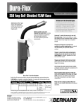
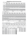
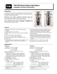
1
FLX34 & FLX54 Series Rotary Sprinklers Installation and Service Instructions Introduction The FLX34 and FLX54 series full-circle rotary sprinklers are designed specifically for golf course applications. Manufactured from durable, high-strength engineering plastic and stainless‑steel components, these sprinklers incorporate many innovative and time-proven features for lasting, maintenance-free operation. Prior to installing the sprinkler, read through the recommended installation and start-up procedures. Please observe all Warnings and Cautions when installing and operating this equipment. Features • • • • • • • • • • • • Full circle (360°) arc coverage Dual trajectory main nozzle adjustment – 25° standard or 15° low angle Two additional front nozzle positions Industry’s largest precision nozzle selection All nozzles are color coded, debris tolerant and threaded in from the front Five electric and two hydraulic activation types o Electric – Satellite systems – Standard 24 VAC solenoid; SPIKEGUARD 24VAC solenoid; Nickel plated SPIKEGUARD 24VAC solenoid o Electric – 2-wire systems – DC Latching solenoid; Integrated GDC module w/DC latching solenoid o Hydraulic – Normally Open valve in head; Check-O-Matic (requires remote valve) Constant velocity drive and variable stator provide consistent rotation speeds Manual control at the sprinkler ON-OFF-AUTO (electric models only) Selectable/lockable pressure regulation settings; 50 psi (3,4 bar), 65 psi (4,5 bar), 80 psi (5,5 bar) or 100 psi (6,9 bar) Indestructable stainless steel valve seat and valve communication tube Body inlet rock screen serviceable from the top All internal components are serviceable from the top of the sprinkler Specifications and Performance/Application Data FLX34 Series • • • • • • • • • • • • • • • Radius: 52'–91' (15,8–27,7 m) Flow Rate: 13–46.9 GPM (49,2–177,5 LPM) Trajectory: Selectable 15° or 25° Arc: Full Circle (360°) Recommended Operating Pressure: 65–100 PSI (4,5–6,9 Bar) Minimum Pressure: 40 PSI (2,8 Bar) Maximum Pressure: 150 PSI (10,3 Bar) Precipitation Rate: Minimum: 0.39"/hr (9,9 mm/hr) Maximum: 0.79"/hr (20,1 mm/hr) Body Height: 10" (254 mm) Pop-Up Height to Nozzle: 4 3/16" (106 mm) Inlet Size: 1" (25 mm) NPT, BSP or ACME Five electric activation types: Standard Solenoid - 24 VAC, 50/60 Hz, 0.30 Amps Inrush, 0.20 Amps Holding SPIKEGUARD Solenoid - 24 VAC, 50/60 Hz, 0.12 Amp Inrush, 0.10 Amp Holding Nickel Plated SPIKEGUARD Solenoid - 24 VAC, 50/60 Hz, 0.12 Amp Inrush, 0.10 Amp Holding DC Latching Solenoid - Momentary Low Voltage Pulse Integrated GDC Module w/ DC Latching Solenoid Momentary Low Voltage Pulse Manual Control (Electric VIH only): On-Off-Auto Check-O-Matic Model checks up to 37' (11,2 m) of elevation Seven Nozzle Variations FLX54 Series • • • • • • • • • • • • • • • Radius: 52'–99' (15,8–30,2 m) Flow Rate: 13.2–61.8 GPM (50–234 LPM) Trajectory: Selectable 15° or 25° Arc: Full Circle (360°) Recommended Operating Pressure: 65–100 PSI (4,5–6,9 Bar) Minimum Pressure: 40 PSI (2,8 Bar) Maximum Pressure: 150 PSI (10,3 Bar) Precipitation Rate: Minimum: 0.38"/hr (9,7 mm/hr) Maximum: 0.77"/hr (19,6 mm/hr) Body Height: 11" (289 mm) Pop-Up Height to Nozzle: 4 3/16" (106 mm) Inlet Size: 1.5" (40 mm) NPT, BSP or ACME Five electric activation types: Standard Solenoid - 24 VAC, 50/60 Hz, 0.30 Amps Inrush, 0.20 Amps Holding SPIKEGUARD Solenoid - 24 VAC, 50/60 Hz, 0.12 Amp Inrush, 0.10 Amp Holding Nickel Plated SPIKEGUARD Solenoid - 24 VAC, 50/60 Hz, 0.12 Amp Inrush, 0.10 Amp Holding DC Latching Solenoid - Momentary Low Voltage Pulse Integrated GDC Module w/ DC Latching Solenoid Momentary Low Voltage Pulse Manual Control (Electric VIH only): On-Off-Auto Check-O-Matic Model checks up to 37' (11,2 m) of elevation Nine Nozzle Variations Nozzle Performance Chart FLX34 Series Performance Chart—25° Nozzle Set 31 Front Nozzle Positions Nozzle Set 32 Nozzle Set 33 Nozzle Set 34 Nozzle Set 35 Nozzle Set 36 Nozzle Set 37 (Yellow) (Blue) (Brown) (Orange) (Green) (Gray) (Black) 102-0725 102-7001 102-0727 102-7002 102-6908 102-0730 102-4261 Red Plug Red Plug Red Plug Red Plug Red Plug Red Plug Red Plug Red Plug Red Plug Red Plug Red Plug Red Plug Red Plug Red Plug 102-4335 102-4335 102-4335 102-4335 102-4335 102-4335 102-4335 102-4335 102-4335 102-4335 102-4335 102-4335 102-4335 102-4335 Back Nozzle Positions PSI 50 65 80 100 Yellow Blue Yellow Orange Yellow Red Yellow Beige Yellow Beige Yellow Red Yellow Gray 102-6937 102-2925 102-6937 102-2926 102-6937 102-2928 102-6937 102-2929 102-6937 102-2929 102-6937 102-6944 102-6937 102-6945 Radius 57 58 60 62 GPM 13.0 14.6 16.2 17.9 Radius 58 60 63 66 GPM 15.5 18.0 20.5 23.4 Radius 64 68 72 75 GPM 21.9 24.4 26.9 29.8 Radius 68 72 76 79 GPM 24.4 28.1 31.1 34.9 Radius — 76 80 84 GPM — 32.2 35.6 39.3 Radius — — 83 88 GPM — — 38.2 43.4 Radius — — 85 91 GPM — — 41.5 46.9 GPM 21.7 24.2 26.6 29.5 Radius 62 64 69 71 GPM 25.5 28.0 31.0 33.9 Radius — 67 73 75 GPM — 32.1 35.5 38.4 Radius GPM — — — — 76 38.0 80 43.1 102-1940 White Radius — — 77 81 GPM — — 41.3 46.8 FLX34 Series Performance Chart—15° PSI 50 65 80 100 Stator Radius 52 53 56 57 GPM 12.9 14.4 16.0 17.5 Radius 53 54 57 59 GPM Radius 15.6 60 17.1 61 19.0 65 20.5 67 102-6929 Blue Conversions FLX34-3134 FLX34-3537 ■ Not recommended at these pressures. Radius shown in feet. Toro recommends the use of a 11⁄4" swing joint at flows over 25‑GPM (95‑LPM). Sprinkler radius data collected in Toro’s zero wind test facility per ASAE standard S398.1. Actual site conditions must be considered when selecting the appropriate nozzle. All sprinklers are equipped with the selectable pilot valve that allows settings at 50, 65, 80 and 100 PSI. FLX54 Series Performance Chart—25° Nozzle Set 51 Front Nozzle Positions Nozzle Set 52 Nozzle Set 53 Nozzle Set 54 Nozzle Set 55 Nozzle Set 56 Nozzle Set 57 Nozzle Set 58 Nozzle Set 59 (Yellow) (Blue) (Brown) (Orange) (Green) (Gray) (Black) (Red) (Beige) 102-0725 102-7001 102-0727 102-7002 102-6908 102-0730 102-4261 102-4260 102-4259 Red Plug Red Plug Red Plug Red Plug Red Plug Red Plug Red Plug Red Plug Red Plug Red Plug Red Plug Red Plug Red Plug Brown Red Plug Brown Red Plug Red Plug 102-4335 102-4335 102-4335 102-4335 102-4335 102-4335 102-4335 102-4335 102-4335 102-4335 102-4335 102-4335 102-4335 102-6883 102-4335 102-6883 102-4335 102-4335 Back Nozzle Positions PSI 50 65 80 100 Yellow Blue Yellow Orange Yellow Radius 58 60 61 63 GPM 13.2 14.8 16.4 18.1 Radius 59 61 64 67 GPM 15.7 17.5 20.0 23.6 Radius 64 68 72 75 FLX54 Series Performance Chart—15° PSI 50 65 80 100 Red Yellow Beige Yellow Beige Yellow Red Yellow Gray Yellow Gray Yellow Gray 102-6937 102-2925 102-6937 102-2926 102-6937 102-2928 102-6937 102-2929 102-6937 102-2929 102-6937 102-6944 102-6937 102-6945 102-6937 102-6945 102-6937 102-6945 Radius 52 53 56 58 GPM 13.2 14.8 16.4 18.1 Radius 53 54 58 60 GPM 15.8 17.4 19.4 21.1 Radius 61 63 68 71 GPM 22.0 24.8 27.6 30.4 Radius 70 74 78 81 GPM 26.2 29.3 32.6 36.7 Radius — 79 83 87 GPM — 34.2 38.0 42.5 Radius — — 85 90 GPM — — 40.7 45.8 Radius — — 87 93 GPM — — 44.9 50.2 Radius — — 91 95 GPM — — 50.2 55.4 Radius — — 96 99 GPM — — 55.6 61.8 GPM 22.0 24.8 27.6 30.4 Radius 65 67 72 75 GPM 26.0 29.2 32.5 36.4 Radius — 69 75 79 GPM — 34.1 37.8 42.3 Radius — — 79 84 GPM — — 40.4 45.5 Radius — — 81 87 GPM — — 44.6 49.9 Radius — — 85 89 GPM — — 49.9 55.1 Radius — — 87 94 GPM — — 55.3 61.5 Stator 102-6929 Blue 102-1940 White 102-1941 White Conversions FLX54-5154 FLX54-5558 FLX54-59 ■ Not recommended at these pressures. Radius shown in feet. Toro recommends the use of a 11⁄4" swing joint at flows over 25‑GPM (95‑LPM). Sprinkler radius data collected in Toro’s zero wind test facility per ASAE standard S398.1. Actual site conditions must be considered when selecting the appropriate nozzle. All sprinklers are equipped with the selectable pilot valve that allows settings at 50, 65, 80 and 100 PSI. Sprinkler Spacing Guidelines Precipitation Rate Formulas • Square Spacing • Square-spaced sprinklers in pattern: No wind - 55% of diameter 4 mph wind - 50% of diameter 8 mph wind - 45% of diameter • Triangular Spacing No wind - 60% of diameter 4 mph wind - 55% of diameter 8 mph wind - 50% of diameter • Single-Row Spacing No wind - 50% of diameter 4 mph wind - 50% of diameter 8 mph wind - 45% of diameter Note: Designing for zero (0) mph wind conditions is not recommended. Design for worst wind conditions. For additional information, refer to Toro Technical Data Manual, form number 490-1737. GPM of full circle x 96.3 (Spacing)2 • Triangular-spaced sprinklers in pattern: GPM of full circle x 96.3 (Spacing)2 (0.866) • Area and flow: Total GPM of zone x 96.3 Total irrigated Square feet of zone • Single row: GPM of full circle x 96.3 (Spacing) (Scallop) Toro Swing Joints Use Toro swing joints to connect the sprinklers to the lateral/main line pipe. Toro swing joints provide swivel joints that allow the sprinkler body to be easily positioned to finished grade and prevents pipe breakage by providing the flexibility to allow downward movement if the sprinkler is run over by heavy equipment. Figure 1 For installation using pipe thread connections (NPT or BSP), use PTFE tape only to seal all threaded connections. CAUTION: Use PTFE tape only for sealing pipe thread connections. Use of pipe dope or other paste sealants can cause deterioration of the sprinkler body threads. Tape should be applied to the male threaded fitting in compliance with the tape manufacturer recommendations. Thread the fitting into the mating female threaded fitting in the sprinkler body and service tee and tighten securely. For installation using ACME thread connections, do not apply additional sealant. CAUTION: ACME fittings incorporate an o-ring seal that requires no additional sealant. Sprinkler fitting installation - Thread the ACME fitting into the sprinkler body and hand tighten until it stops. No additional tightening or loosening is required. CAUTION: Loosening beyond 270° will result in a thread leak. Lateral/Mainline pipe installation - Thread the ACME fitting into the lateral/main line service tee and hand tighten until it stops, then loosen up to one full turn to ensure flexible movement of the swing joint. Wire Splices CAUTION: Communication cable or station wire connections will deteriorate when exposed to moisture and earth ground causing shorts or open circuits resulting in improper system operation. All direct burial wire connections must be done with approved waterproof connections installed in compliance with the manufacturer specifications. Contact your Toro Golf Distributor for approved waterproof connectors. Always provide a wire service loop for each splice to ensure sufficient wire is available should future servicing be required. Connecting Hydraulic Control Tubing Step 1 – Route control tubing from the controller to the sprinkler location(s). Note: Leave an 18" (45.7 cm) service loop of tubing at each sprinkler to facilitate movement of sprinkler and service operations. Refer to Hydraulic Control Systems Table for tubing run length and sprinkler elevation information. Step 2 – Flush tubing thoroughly to remove all air and debris. Step 3 – Remove the tube retainer and poly cap from the tubing adapter at the base of the sprinkler. Step 4 – Slide the tube retainer over the end of the control tubing and attach tubing to adapter. Step 5 – Slide tube retainer over the adapter area to secure tubing. Hydraulic Control Systems Table Type of System* Maximum Distance From Controller Elevation Restrictions Normally Open (01) with 3/16" Control Tubing 500' Valve elevation should not exceed 25' above controller elevation or 70' below controller elevation. Normally Open (01) with 1/4" Control Tubing 1000' Valve elevation should not exceed 25' above controller elevation or 70' below controller elevation * -All hydraulic connections on Toro valves are 1/4" insert type. -Control line pressure must be equal to or greater than mainline pressure. -Control line pressure range is 40 to 150 PSI. System Start Up WARNING! Never stand or lean over the sprinkler while the irrigation system is being filled, during manual or automatic operation or when performing sprinkler service procedures. Direct contact with irrigation spray, a failed or improperly installed sprinkler connection or sprinkler components forcibly ejected upward under pressure can cause serious injury. The following is a recommended procedure that will protect system components during system start-up. The procedure is based on a velocity fill rate of less than 2' (.61 m) per second. See Table 3 below. Step 1 – Use a jockey pump only to fill the system at a velocity fill rate of less than 2' (0.61 m) per second. CAUTION: Failure to comply with recommended fill rate will increase line pressure resulting in a water hammer effect that could damage sprinklers and piping components. See Warning above. Step 2 – Use quick coupler keys at all tees and greens with quick coupler valves to bleed air from the system lines during the filling process. For best results, do not compress air and then relieve it – bleed the air continuously while filling the system. Step 3 – After water has filled all lines and all air is removed, remove the quick coupler keys. Recommended System Fill Rate Pipe Size Flow Velocity Pipe Size Flow Velocity in. cm GPM LPM ft/secm/sec in. cm GPM LPM ft/secm/sec 1/2 1.3 2 7.6 1.600.49 3 7.6 45 170.3 1.860.57 3/41.9 311.41.92 0.59410.1 75 283.91.87 0.57 1 2.5 518.91.50 0.46615.2 150 567.81.73 0.53 1-1/4 3.1 10 37.9 1.860.57 8 20.2 250946.3 1.700.52 1-1/23.8 1037.9 1.410.431025.4 450 1703.01.970.60 2 5.0 2075.7 1.800.551230.5 500 1893.01.550.47 2-1/2 6.4 30 113.6 1.84 0.56 Winterization Trajectory Adjustment Procedure Winterizing the irrigation system is required in freezing climates to prevent damage from water expansion when it freezes. Following are three key points for successfully winterizing the system, however, Toro provides a complete “Winterization and Pressurization Guide” (P/N 373-0849) that is available from your local Toro Distributor. • Open low point drains, vent high points and allow the system to drain naturally several days prior to using compressed air. • Attach compressor to the highest point possible and use the compressed air to force remaining water out of the low points and close vents and drains working from high points to low points when clear air is observed. • Regulate compressed air to 50 psi and cycle each sprinkler ONCE until clear. The FLX34 and FLX54 sprinkler models are designed with a dual-trajectory main nozzle. Use the following procedure to select the sprinkler trajection of 15° or 25°. Step 1 – Using the multi-purpose tool (P/N 995-83), pull the riser from the provided slot in the cap. Pull the riser assembly until there is enough clearance for handling and hold onto the riser body. Step 2 – Remove cap screw and cap to unlock the main nozzle. Step 3 – Use a 5/8" nut driver (P/N 995-99) to turn the main nozzle assembly. Turn the main nozzle assembly clockwise until the angle indicator points towards the right to set 25° trajection. Continue turning the main nozzle clockwise until the angle indicator points towards the left to set 15° trajection. See Figure 2 and 3. Step 4 – Replace the cap. Make sure the main nozzle is secured and retained by the cap. Step 5 – Secure the cap with the cap screw. Figure 2 Figure 3 25° 15° Radius Reduction - FLX34/54 and FLX35/55 Only (Not for FLX35-6/55-6) For further refinement of the sprinkler’s radius, an optional radius reduction screw (363-4839) can be added to break up the main nozzle spray. The sprinkler cap provides an installation hole just above and in front of the main nozzle. Using a 3/32" Allen wrench (P/N 995-82), thread the radius reduction screw clockwise into the installation hole. Turn the sprinkler ON and continue to thread the screw clockwise into the main nozzle stream until the desired result is achieved. See Figure 4. Figure 4 Pilot Valve Operation (Electric Models Only) The pilot valve controls the operation of the main valve located in the base of the sprinkler body. The main valve is operated by the release of water metered through the pilot valve when it is activated either manually at the sprinkler or by the irrigation system controller. Another important function of the pilot valve is to regulate the water pressure to the sprinkler nozzle. Pressure regulation compensates for large variations within the system and maintains a constant pressure for optimum sprinkler operation. The pilot valve is factory set to regulate one of four pressure levels: 50 psi (3.5 bar), 65 psi (4.6 bar), 80 psi (5.6 bar) or 100 PSI (7.0 bar). Change the pilot valve operating pressure by loosening the thumb screw that secures the selector lever. Position the selector lever to the desired operating pressure and hand-tighten the nut. Figure 5 See Figure 5. Troubleshooting Possible equipment failures with causes and corrective action are listed below. Sprinkler won’t rotate – Debris wedged between stator and turbine • Remove obstruction – Drive assembly defective • Replace drive assembly – Nozzle base assembly defective • Replace riser assembly Head sticks up – Dirt in riser assembly • Flush out. (See Flushing Sprinklers) – Damaged or missing return spring • Replace – Damaged riser • Replace Poor distribution pattern – Nozzle plugged with debris • Clean or replace nozzle – Nozzle orifice damaged • Replace nozzle – Low operating pressure • Determine why system overloaded and correct Valve won’t close (Electric) – Continuous 24 VAC to sprinkler • Check controller for voltage source – Debris in Pilot Valve • Disassemble and remove all debris – Leak in pilot valve assembly • Replace pilot valve assembly – Plugged supply screen on piston • Clean or replace screen – Manual control selector on pilot valve assembly turned to “ON” position • Turn to “AUTO” position – Plunger movement restricted • Inspect and clean or replace – Valve cylinder misaligned with sprinkler body communication tube • Remove valve assembly and install correctly – Foreign object keeping valve from seating • Remove, clean and check valve for damage. Replace if necessary – Damaged piston seal or piston assembly • Replace valve assembly 100 PSI (7.0 kg/cm2) 80 PSI (5.6 kg/cm2) 65 PSI (4.6 kg/cm2) 50 PSI (3.5 kg/cm2) Valve won’t close (Hydraulic) – Leak in control tubing • Isolate and repair – Pilot valve leak in controller • Confirm by observing constant dripping from discharge line of controller. Refer to Controller Service Manual – Valve cylinder misaligned with sprinkler body communication tube • Remove valve assembly and install correctly – Foreign object keeping valve from seating • Remove, clean and check valve for damage. Replace if necessary – Damaged piston seal or piston assembly • Replace valve assembly Valve won’t open (Electric) – Control (field) wires severed • Isolate and repair – No power to controller • Establish controller power – No power from controller to solenoid • Check for blown fuse and replace – Manual control selector on pilot valve assembly turned to “OFF” position • Turn to “AUTO” position – Pilot valve solenoid inoperative • Remove and replace – Pilot valve plunger movement restricted • Inspect, clean and/or replace – No supply from main valve • Debris in control tube, main valve assembly and/or communication passages in body. Flush thoroughly Valve won’t open (Hydraulic) – Plugged controller discharge line or discharge port in pilot valve • Verify by checking for discharge at discharge line when station is activated. If no discharge, refer to Controller Service Manual Sprinkler Weeping (Slow leak in valve) – Damaged or blocked valve seat • Remove blockage and, if necessary, replace valve assembly – Damaged piston seal or piston assembly • Replace valve assembly – Damaged pilot valve discharge seat • Clean or replace pilot valve – Damaged pilot valve plunger • Clean or replace plunger – Low pressure on supply line (N.O. Hydraulic Models) • Check for low pressure reason and correct – Elevation of normally closed sprinkler exceeds 75' (22.9 m) differential Several valves on different stations fail to close (Hydraulic) – Control tubing leak which lowers supply pressure to other stations • Turn controller from station to station until a station is reached where only valves on that station stay open The leak would be in the tubing on that station. Isolate and repair – Leak in supply line to controller • Verify by checking pressure in all control lines – Leak in controller pilot valve • Verify by constant discharge from controller – Plugged supply line filter • Replace filter if more than 3 psi (0.21 bar) differential exists Servicing Procedures The FLX34 and FLX54 series sprinklers are designed to provide the user trouble-free operation for many years without scheduled maintenance. If it becomes necessary to disassemble the sprinkler to correct a malfunction or replace a component, all internal parts of the sprinkler can be accessed from the top. Refer to the Troubleshooting Procedure in this manual in the event of a malfunction. Some special tools are required for disassembly and/or maintenance of the sprinkler and are available from your Toro dealer. Servicing Sprinkler Mechanism WARNING! Never stand or lean over the sprinkler while the irrigation system is being filled, during manual or automatic operation or when performing sprinkler service procedures. Direct contact with irrigation spray, a failed or improperly installed sprinkler connection or sprinkler components forcibly ejected upward under pressure can cause serious injury. Note: Refer to Figure 6 for the following procedure. Figure 6 1 2 Step 1 – Insert the hooked end of the multi-purpose tool (P/N 995-83) into the slot in the cap (3) and pull the riser assembly up until there is 3 enough clearance to handle. 5 Step 2 – Insert the hooked end of the tool into the snap ring slot (11). Pull 6 the snap ring inward towards the sprinkler assembly, then upward 4 to remove from the groove in body. Hold onto the riser body (16) 7 and carefully extract it from the sprinkler body. 8 9 10 CAUTION: The seal/retainer (12) will rapidly move upward (caused by the decompressing spring [14]) as it clears the sprinkler body. 7 Step 3 – Using a 5/8" nut driver (P/N 995-99), unscrew main nozzle (10) from 11 main nozzle housing (8). 15 Step 4 – Using a 5/16" nut driver (P/N 995-105), unscrew the intermediate 12 nozzle (6) and inner nozzle (5) and plugs (7) from the nozzle base assembly. 16 Note: During reassembly, ensure that the inner nozzle orifice is aligned as shown. 13 Step 5 – Depress seal retainer (12) and spring (14), then remove cap screw (1) and cap (3). Step 6 – Carefully release tension from return spring. 14 17 Step 7 – Remove spring and seal retainer/o-ring assembly (12, 13 and 14). Step 8 – Grasp the riser (16) firmly and hold in place while removing nozzle base (4). Turn nozzle base assembly counter-clockwise to remove. 18 Step 9 – Remove o-ring (15) from top of riser assembly. Step 10 –Three small tabs are provided on the edge of the multi-purpose 19 tool. Insert tabs into the debris filter screen (19). Holding the plastic base of riser assembly, turn the screen counterclockwise to remove. Step 11 –Remove drive assembly (17) and stator (18) from riser assembly by carefully pressing on end of threaded shaft. Step 12 –Thoroughly clean and inspect all parts and replace as necessary. Reassemble in the reverse order. Note: During reassembly, ensure snap ring is correctly installed and fully seated in snap ring groove. Servicing Main Valve WARNING! If the valve snap ring is difficult to remove, residual water pressure may be remaining in the system. To prevent possible serious injury due to valve being ejected upward under pressure, confirm the following conditions exist prior to removing the snap ring and valve. A. Water supply to sprinkler is shut off at source. B. All pressure is bled from system, including control tubes. C. AC power is disconnected at source. Step 1 – See WARNING above. To remove valve assembly, Figure 7 Figure 8 squeeze snap ring ears together with snap ring pliers (P/N 995-100) and remove snap ring from sprinkler body. See Figure 7. Step 2 – Use valve removal tool P/N 995-08 for FLX34 or 995-09 for FLX54 to remove valve assembly from base of sprinkler body. Valve removal tool is inserted into sprinkler body and pushed through valve ribs. A slight twist will catch tool under ribs enabling valve removal by pulling straight up and out. See Figure 8. Note: If valve removal tool is not available, use snap ring pliers to grasp rib of valve cylinder assembly and pull up and out of sprinkler body. Step 3 – Reinstall valve assembly using valve insertion tool P/N 995-76 for FLX34 or 995-101 for FLX54 as follows: • Load snap ring onto insertion tool carrier with stepped side against carrier as shown in Figure 9. While holding snap ring in compressed position, slide retainer clip in to hold snap ring ears • Load valve assembly on carrier as shown. • Locate position of communication tube in bottom of sprinkler body and orient insertion tool accordingly. • Insert tool straight down into sprinkler body aligning bosses on t-handle with holes on sprinkler body flange. When valve assembly clears vertical side wall ribs inside body, pull up on snap ring release mechanism (FLX54 models only) and press valve assembly into position. Snap ring will lock into groove when properly installed. Remove insertion tool and check snap ring to confirm that it is fully seated in groove. Figure 9 Snap Ring Release Mechanism Snap Ring In Retainer Clip Stepped Side of Snap Ring Valve Assembly Orientation In Carrier Press Valve Assembly Into Position Snap Ring Released Servicing Pilot Valve WARNING! Never stand or lean over the sprinkler while the irrigation system is being filled, during manual or automatic operation or when performing sprinkler service procedures. Direct contact with irrigation spray, a failed or improperly installed sprinkler connection or sprinkler components forcibly ejected upward under pressure can cause serious injury. Note: Refer to Figure 10 for the following Figure 10 procedure. 15 Step 1 – Make sure that the water supply to sprinkler 9 14 is positively shut off and any residual 10 13 pressure has been bled off. If the sprinkler is 8 12 pressurized, main valve will open when the pilot 11 16 valve is disconnected from control tube. Step 2 – Carefully remove turf and soil from the side of 1 7 the sprinkler to expose pilot valve and control 5 tubing. 2 17 Step 3 – Remove the two retaining screws from the pilot 6 18 valve housing. 3 Step 4 – Pull the pilot valve assembly away from the sprinkler body and cut the control tubing just below tube retainer. Unless pilot valve has 4 been previously removed, control tubing length will be sufficient for re-connection. Step 5 – Remove tube retainer and remaining piece of control tubing from valve body fitting. Step 6 – Remove the solenoid (1, 2 or 3) or Normally Closed actuator (4) by turning it counterclockwise. Step 7 – Remove the retaining nut (18) and washer (17) from the pressure adjuster (11) and pull the pilot valve body assembly out of housing (16). Step 8 – Remove diaphragm assembly (15), piston (14), spring (13), traveling adjuster (12), pressure adjuster (11) and o-ring (7). Step 9 – Remove selector shaft assembly (9) and plunger assembly (5). (The selector shaft retains the plunger in the valve body.) Step 10 –Thoroughly clean and inspect all parts. Replace damaged parts as necessary and reassemble in reverse order. Note: For service part numbers, refer to www.toro.com and click Parts. Select the “Irrigation” category and search for “Pilot Valves”. Flushing Sprinklers WARNING! Never stand or lean over the sprinkler while the irrigation system is being filled, during manual or automatic operation or when performing sprinkler service procedures. Direct contact with irrigation spray, a failed or improperly installed sprinkler connection or sprinkler components forcibly ejected upward under pressure can cause serious injury. Step 1 – With sprinkler operating, carefully step down on center of cap several times. Water will flow around riser and flush out debris. Step 2 – Cycle sprinkler on and off several times to check for proper retraction. Cap should be even with top of body flange when fully retracted. If riser sticks in up position, check for debris lodged between riser and body. Flush out all debris. Remove sprinkler mechanism if necessary. NOTES: NOTES: © 2015 • The Toro Company, Irrigation Division • www.toro.com Form Number 373-0858 Rev. A