1
4-2010
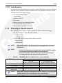
3. Step-By-Step Outline of Installation
3.6.3.1 Transfer Switch Communications Wires
WARNING: Interconnecting the generator set and the public utility can lead to the
electrocution of personnel working on the utility lines, damage to equipment
and fire. An approved switching device must be used to prevent
interconnections.
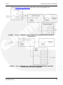
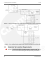
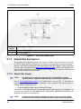
Install the transfer switch in accordance with its Installation Manual.
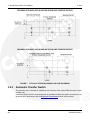
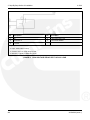
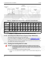
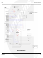
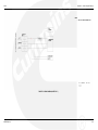
Wiring harnesses are available in various lengths for quick connection between the generator
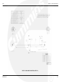
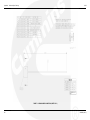
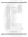
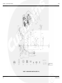
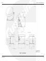
set and transfer switch. See the Outline and System Drawings for harness details.
3.6.4
Heater and Outlet Connections
3.6.4.1 120 Volt Optional Accessories
NOTE:
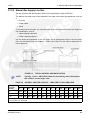
To supply 120 VAC to power the following accessories, connect 12 AWG 75 °C wires to the
accessory wires in the 120 volt junction box from a 15 amp protected circuit in the main
distribution panel in the house.
· Optional battery heater
· Optional engine heater and alternator drier assembly
· Optional installer-supplied GFCI outlet
· Optional carburetor heater
NOTE:
3.6.5
The wires my be run through the same conduit as the AC power output wires.
Operator Panel
3.6.5.1 Operator Panel Communication Wires
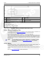
Wiring harnesses are available in various lengths for quick connection between the generator
set and in-home display. See the Outline and System Drawings for harness details.
Class 1 wiring methods should be used for the in-home display, Ethernet and transfer switch
communication conductors between the generator set and transfer switch. Separation of Class 2
and power circuits should be maintained per Article 725.136 of 2008 NFPA 70: National
Electrical Code.
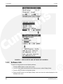
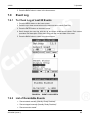
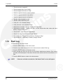
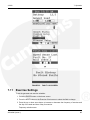
See the Operator Manual (A029V091) for information regarding using the operator panel to
operate and monitor the generator set.
3.6.5.2 Operator Panel Installation In The Home
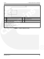
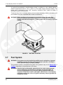
Mount the generator set operator panel on a wall, in a convenient location such as next to the
house thermostat.
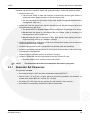
To install the operator panel:
· In drywall or paneled walls:
1. Drill a hole that is large enough to clear the harness connector on the back of the
operator panel.
2. Route the wires inside the wall, to hide the wires.
A029V090 (Issue 1)
21