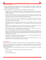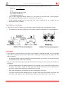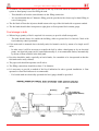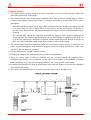
1
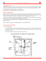
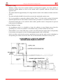
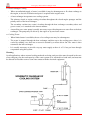
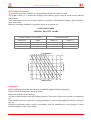
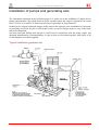
Emergency Relief Items Catalogue 2002 Installation of pumps and generating sets The information contained in the following pages is to assist you in the installation of engine driven pumps and generators .We would, however, point out that because the range of equipment can extend from 1 kVA to over 1000 kVA it has been necessary to generalise in many instances. Should you be in doubt, technical support at HQ can provide expertise in the installation of your pump or generating set. Please feel free to call on this service, as errors in design can prove very costly at the end of the installation. Servicing and fault finding must always be carried out in conjunction with the pump, engine and alternator manufacturers recommendations. A copy of their service manual together with copies of all circuit diagrams are usually supplied. Typical installation generator set Water and Sanitation 451 Emergency Relief Items Catalogue 2002 General information Nearly all generating sets and pumping sets are capable of running on any outdoor or indoor solid foundations. Where adverse weather is likely it is recommended the unit is supplied complete with canopy or similar method of covering. For fixed installations it is advised to take into consideration the following points: - Foundations: The room and floor should be of solid construction with a concrete floor and have adequate space for the servicing of the equipment. The foundations should also be flat and level. See also next chapter. - Trenches: Trenches should be allowed in the floor for both fuel pipe work and cables. They should never be run in the same trench. With cable trenches you must always take into account the bend radius of the cable when determining the depth of the trench. - Ventilation: For water-cooled or air cooled engines the room should have adequate ventilation with either louvered inlet and outlets or extractor fans. The importance of cooling air inlets and hot air outlets cannot be over stressed. - Fuel Supply: It is most important that sufficient fuel and easy handling facilities are provided with the generating set. On unattended sites, it is recommended to provide an automatic 'top up' system. - Exhaust System: The exhaust must always be taken to the outside of the building and care should be taken to ensure that the fumes or noise do not cause inconvenience to others. - Noise attenuation: Advice on attenuation can be provided so as to reduce the noise level in degrees to a level which is virtually inaudible outside the building. - Fire precautions and Warning notices: It is strongly recommended to provide fire protection for all types of fire likely to occur in the engine room together with warning notices showing the dangerous parts of the machinery and control panel. Please consult with your fire officer as to the best methods of fire control. - Switchgear: Your control panel should be placed with easy access and the installation and repair should only be attempted by competent electricians. - Commissioning: Technical support group can provide a pre-commissioning check of your installation and can fully commission the plant if you require. Foundations For existing concrete foundations if in doubt as to the load carrying capabilities it is advisable to consult a structural engineer. He/she will require the weight and dimensions of the unit showing the fixing points and also the type of equipment so as to check that all vibrations produced by the set running will be absorbed. For new foundations the following information will be required when calculating the size and depth of the base: - Total size of the unit (add 300mm to length and width for the foundations) - Total net weight - Type of mounting provided 452 Water and Sanitation Emergency Relief Items Catalogue 2002 - To calculate the necessary foundation depth the following formula should be used: Depth (m) = W . 2402.8 x B x L where: W =Total net weight of set (kg) B =Foundation width (m) L =Foundation length (m) - This is with a suggested concrete mixture of 1 part cement, 2 parts sand, and 3 parts aggregate. The foundations should be reinforced with steel reinforcing bars. - If anti-vibration mounts are not used, add 25% to the weight of the set to allow for the transmission of the vibration. Anti vibration mountings These are two types of mounts, one with rubber isolators and the other with adjustable springs. - The mounts are delivered with the sets in accordance with the manufacturer's recommendations. Fuel tanks You will have received with your set either a set mounted or separate fuel tank. The set mounted tank will be already connected to the engine and no other pipe work between the engine and fuel tank is required. - If a separate tank is provided it should be positioned within easy reach of the engine fuel pump and should be either wall or floor mounted. Engines without fuel lift pumps require the fuel tank to be at least 0.6 metres above the fuel inlet on the engine. - The fuel connections to the engine should always be flexible so as to absorb the vibration when the engine starts and is running. All other pipe work should be run in the size recommended in trenches or strapped and protected to either the floor or walls. - Pipe work should not be galvanised as the zinc is attacked by diesel fuel. - The outlet of the fuel tank should always be at least 25mm above the bottom of the tank and preferably at the opposite end to the drain plug. Both the outlets should have on/off valves. Water and Sanitation 453 Emergency Relief Items Catalogue 2002 A suitable vent connection must be provided in the top of the tank when an automatic fuel transfer system or hand pump is used for filling the tank. - This should be at least the same diameter as the filling connection. - It is recommended that a 3"diameter filling point be provided with a brass cap for hand filling in case of emergency. The fuel leak off from the injectors should return to the top of the fuel tank with a separate conduit. The fuel tank should either incorporate a sight glass or float operated fuel contents gauge. Fuel storage in bulk When a large quantity of fuel is required it is necessary to provide a bulk storage tank. - The tank should always be outside the building, either at ground level or burried. Check with local authority what is permitted. If the main tank is mounted above the daily tank, fuel transfer can be by means of a simple on/off valve. - In other cases it will be necessary to transfer the fuel by either a hand pump or by an electrical pump. An electrical pump can be controlled manually or, in an unattended station, automatically by means of float switches in the daily tank. Provision should be made, especially on buried tanks, for a manhole to be incorporated so that the fuel tank can be easily cleaned. The pipe work should incorporate on/off valves. The filling connections should be at least 3" in diameter. It is necessary to provide a method of fuel level indication for above ground installation. A float operated or visual fuel indicator is recommended. - For buried tanks an electrically operated fuel level gauge should be provided. 454 Water and Sanitation Emergency Relief Items Catalogue 2002 Exhaust system The engine exhaust system should be as short as possible so as to avoid back pressure which will affect the performance of the engine. The exhaust should come off the engine manifold with a short section of flexible pipe or bellows section to the exhaust silencer. By means of solid pipe and bends it is then taken to the outside atmosphere. - All bends should be smooth and of large radius and should the pipe include more than two bends or be more than 6 m (20 ft.) long, then it is necessary to increase the diameter of the pipe to prevent excess back pressure. The engine manufacturer can give advice on the dimension of pipe required. - The exhaust pipe should be supported preferably by hangers with vibration mountings at frequent points. The exhaust pipe should in no case be fixed rigidly or cemented on the wall. Try to avoid long vertical run, should it be required, install a drain plug at the bottom of the pipe to drain away any condensate which would have an adverse effect on the engine. The exhaust gases should not terminate within the area used for engine cooling or aspiration, and where it passes through the room should be lagged to avoid excess heat transmission to the room and also to prevent injury to personnel. Avoid combining two separate exhaust systems. Discharging exhausts into existing flues may present incompatibilities. There are various types of silencers available and your set will normally be supplied with a residential type silencer. Noise reduction can be reduced even further by the addition of another balanced silencer or by a specially designed silencer to meet your specific requirements. If installed horizontally the silencer should slope away from the engine to prevent the condensate from entering the engine. The exhaust run should always be kept well away from any wood or fuel pipe work. Water and Sanitation 455 Emergency Relief Items Catalogue 2002 Lubricating oils Details of the correct lubricating oil can be found in your engine operator handbook supplied with the generating or pumping set. Do not mix two different oils if they are not clearly indicated as “mixable”, as this will have a detrimental effect on your engine. Recommended oils are listed under codes TVECLUBR… Electric start batteries Batteries should be placed as near as possible to the electric starter, preferably on a metal stand with a hardwood cover to prevent fuel, dust or metal objects falling on the terminals. The cover must be clear of the ventilation plugs. Remember to keep the terminals clean and greased at all times. As there are various types of batteries available it is recommended to refer to the instructions supplied with the unit as to the specific gravity and charging rates required. Unless otherwise specified all batteries are dispatched dry charged. Battery acid is not supplied, should be found locally. More information and choice of standard batteries see code EELEBATT… Cooling of the equipment Air Cooled Engines - Air cooled engines require a ducting outlet aperture at least twice as large as the engine outlet because the air is forced over the cylinder in the compressed state increasing the volume of air at the engine air outlet. - The inlet should be half as large again as the engine outlet. 456 Water and Sanitation Emergency Relief Items Catalogue 2002 Radiator Cooling - Radiator cooling is the most common method of cooling diesel engines. It is most suitable to mount the engine radiator as close to the outside wall as possible with the air inlet on the opposite wall. - The outlet should be approximately 25% larger than the matrix of the radiator with the inlet 50% greater. - The inlet and outlet should be louvered to prevent rain entering the engine room. - If it is not possible to mount the radiator within 75mm (3") of the wall a section of ductwork should be placed between the radiator and louvered to prevent the re-circulation of the hot air. - If ductwork bends have to be used the widest radius possible must be incorporated to prevent back pressures building up. Remote Radiator Cooling - On installations where it is desirable to locate the radiator at some distance away from the generating set (i.e. the roof, outdoors or in another room), a remote radiator can be used. - If the radiator is over 10m (30ft) away or above 6m (20ft) from the engine, then it will probably be necessary to incorporate a water circulating pump together with a break tank. - In this case there must be the necessary precautions to prevent the engine room overheating by incorporating an extractor fan in the room. The air inlet should be increased in size by 50%. Water and Sanitation 457 Emergency Relief Items Catalogue 2002 Heat Exchanger Cooling - Where an unlimited supply of water is available it may be advantageous to fit a heat exchange to the engine, as less air circulation and space is required in the engine room. - A heat exchanger incorporates two cooling systems. The primary circuit or engine cooling circulates throughout the closed engine passages and the primary tubes of the heat exchanger. The secondary coolant (raw water) circulates through the heat exchanger secondary tubes and goes to waste, or is returned to the remote radiator. - An auxiliary raw water pump is usually necessary to provide adequate raw water flow to the heat exchanger. The pump may be driven by the engine or by an electric motor. Cooling Tower - When limited water is available, the use of a cooling tower may be advantageous. - The water is pumped through the heat exchanger and then up to the cooling tower where it is cooled by running over slats into a reservoir assisted by a motor driven fan. The water is then returned to the heat exchanger. - It is usually necessary to provide a top up water supply as there is a 3% loss per hour through evaporation using this system. Warning On all applications where external cooling methods are being used provision must be made in the case of an emergency for the total capacity of the water system to be retained in a bund wall, and must not be allowed to flood the room or come into contact with the electrical equipment. 458 Water and Sanitation Emergency Relief Items Catalogue 2002 Anti Freeze Solutions To avoid freezing of the coolant it is essential that an anti freeze solution is used. The graph on Page 31.12 defines the strength of the ethylene glycol required for the lowest ambient temperatures. The coolant approved for use in diesel engines is a mixture of 50%inhibited ethylene glycol and 50% clean fresh water. Mixtures containing methanol or propylene glycol are not approved. SELECTlON TABLE SPECIFIC GRAVITY CHART Coolant mixture (% by volume) Anti-freeze 30 50 60 Water 70 50 40 Protection down to Degree °C -15 -35 -40 Degree °F 15 -31 -40 Alternator Read carefully the alternator manufacturer's handbook supplied with the equipment. However the following points should be noted: Inspect the machine for any damage. Any dirt or dust should be removed from the machine. This can be carried out by means of compressed air. If the machine has been exposed to a damp atmosphere it must be thoroughly dried before being put into use. Electrical connections must be made in accordance with the manufacturer circuit diagram. Consult technical support in case of any doubt. Water and Sanitation 459 Emergency Relief Items Catalogue 2002 Switchgear Set mounted panels are completely wired so no installation or connections between panel and engine/alternator are required. Floor mounted panels, if possible, should be mounted on their own plinths at least 150 mm (6") above the floor level and should have easy access to both front sides and rear for maintenance purposes. If you are restricted for space at the rear of the panel advise your supply department on the order so that the panel can be designed with all cable connections being made at the front or side of the panel. The panel should be bolted to the foundations with 1/2" rawl bolts and should be protected before commissioning with a dust cover. Cabling Please ensure the correct cross sectional area of cable between the alternator/panel and distribution board is used and is adequate to carry the full rated continuous output of the generator, allowing for derating in high ambient temperatures. Butyl rubber EPR or CSP cable is recommended for main connections, allowing for a generous loop before the cable enters the alternator terminal box because of the vibration caused by the set starting. If long cable runs are involved you can run the cable to a terminal box and then use flexible connections between the terminal box and the alternator. For the D.C. wiring to the engine we would normally recommend a 1.5 mm 2 PVC cable, except battery charge circuit which should be 4 mm 2 . Should the panel be more than 10 metres away, give the exact information when ordering, as a cable of larger cross sectional area may be required. Attenuator In cases where noise is a critical factor it is possible to fit noise attenuators to the air inlet and outlets which can be designed to reduce the noise levels in degrees down to a virtually inaudible level. Should your requirements involve the application of noise attenuators you are advised to seek from your technical support advice as to the best methods of noise reduction. Recommended fuels and lubricants See TVECFUEL… and TVECLUBR… Pre-commission check Familiarise yourself with the individual engine and alternators recommendations before attempting to start the set. However generally the following points should be checked before the first start: (a) All connections are tight and leakproof, including cabling to auxiliary terminal box. (b) All protective coverings used in packing are removed. (c) Check the fuel, lubricating oil and coolant levels are adequate; top up if necessary. N.B. Engines will not run efficiently if over filled with oil. (d) If the engine has not been run for a month it may be necessary to prime the turbo charger bearings, if fitted. See engine manufacturer's recommendations. (e) Prime fuel system. (f) Charge batteries and connect to unit. (g) Check alternator connections. 460 Water and Sanitation Emergency Relief Items Catalogue 2002 (h ) Check all protective covers have been removed. Remember relays and timers are clamped for shipment. (i) Check fuses are in holders and correctly rated. (j) Isolate circuit breaker from load. When you are happy all the conditions above have been satisfied, you can now run the set. Should the engine not fire after 20 seconds cranking release the starter, pause for 30 seconds and repeat procedure. If after 4 attempts the engine does not start investigate the cause. Typical maintenance procedure Listed below is a typical maintenance procedure, but you are requested to refer to the manufacturer's handbook for specific requirements related to your engine. Before attempting any maintenance on the engine, disconnect the batteries and on stand by sets, isolate the mains. Daily Check lubricating oil level and top up to level shown on dipstick as necessary. Check coolant level and top up as necessary. Check fuel oil level in daily service tank and replenish as necessary. Weekly Above plus: Check level of electrolyte in battery and top up with distilled water as necessary. Test run plant for 60 minutes preferably on its rated full load. Monthly Above plus: Drain sludge from fuel tank. Inspect injectors and service as necessary. Inspect all filters and service, clean or replace as necessary. Inspect condition of all hoses and belts. Replace and tighten as necessary. Inspect governor and service as necessary. Inspect turbo-charger (if fitted) and prime bearing housing if necessary. Inspect battery charging alternator/dynamo and starter motor. Service and/or replace brushgear if necessary. Inspect all points requiring greasing, including alternator bearings and grease as required. Water and Sanitation 461