1
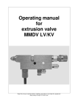
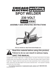
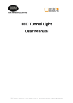
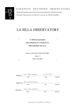
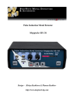
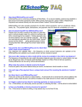
HELIOMOTION
QUICK ASSEMBLY GUIDE
PV-650
PART I - FOUNDATION
M16
1x
1x
8x
M16
4x
2
PLACEMENT
1m
Area around flange must
be clear of obstacles
in a 1 meter radius.
Place the unit in a location
that receives sunlight
throughout the day.
CONFIGURATION
B) FREE STANDING
MAX 1.5m
A) NEAR A WALL
0.4-0.7m
Wall support is required if column
height exceeds 1.5 meters
3
1
Make a hole for the concrete at your chosen
location. Refer to the user manual for
recommended volume.
2
Fill the hole with concrete up to a few
centimeters below ground level.
3
Push the rod unit into center of the
concrete and let the flange rest on
top of it. Use a spirit level to align the
flange horizontally.
Allow the concrete at least 1 week
to set before assemling the remainder
of the power plant. Cover the concrete
with soil after it has cured for 4 weeks.
4
Rod unit
1x
Extension column
4x
8x
1. Adjust bottom nuts to vertically align the column.
2. Tighten top stop nuts to secure the column.
3. Mount any additional columns in the same way.
5
Wall support
1x
2x
4x
2x
1
2
3
1. Fasten the wall support to the column, as high as the wall allows.
2. Adjust the length of the wall support as needed and fasten it to
the wall. If the wall is thin then first reinforce it by bolting a plank
horizontally to the inner or outer side of the wall.
3. Drill a 8mm hole through the inner telescopic rectangular tubes.
Fasten bolts through the holes to secure the wall support.
6
2x
PART II - TRACKER
M10x120
M16x70
M16
4x
8x
M16
4x
1x
7
1x
1x
1x
1
4x
8x
4x
Leave bolts loose
2
1x
A
A
B
1x
C
INDOORS
1x
1x
1. Pull the 4-wire cable through the column using the hole below the balk. A pull wire
simplifies this task.
2. Leave 20 cm of cable sticking out of the hole. Put a cable tie around the balk and
the cable to relieve strain from the cable hanging inside the column.
3. Remove the outer insulation from 10 cm of the cable and then remove the top
7 mm of inner insulation from each of the four wires.
4. Make holes for each of the four wires in the outdoor junction box (A) using a
screwdriver at the illustrated locations. Carefully push the wires into the junction box
through the elastic membrane.
5. Connect the wires to the ±24V terminal and one of the ±TE terminals. Make a note
of which wire color is connected to which terminal and polarity.
6. Wire the underground cable to the house and then bury it below ground. To
provide access to the burried cable in the future it is advisable to run the
underground part of the cable through a flexible conduit.
7. Mount the indoor junction box (B) on a wall inside using two screws and pull the
cable inside the box.
8. Connect the four wires to the terminal block inside the indoor junction box (B).
9. Fasten the power adapter (C) near the indoor junction box. Connect the power
adapter's wires to the ±24V wires in the indoor junction box. The red wire from the
adapter is +24V.
8
3
F
The tracker needs to be turned to face true
south in the northern hemisphere or true north in
the southern hemisphere. To do so follow these
steps.
Alternative 1:
1. Power on the tracker by plugging in the
power adapter.
2. The tracker will move to its initial position,
calibrate itself using GPS, and then proceed to
the sun's calculated position.
3. Temporarily fasten an M10 bolt to the flange
on top of the tracker in one of the holes next to
the forward marker (F).
4. When the tracker has reached the sun's
calculated position, rotate the tracker so that
the shadow from the bolt aligns with the hole
behind it. This step requires sunshine.
5. Remove the temporary bolt and unplug the
power adapter.
6. Tighten the bolts holding the tracker to the
foundation column.
Alternative 2:
1. Use a smart phone with a GPS compensated
compass.
2. Place the phone below the balk and align it
to true south (or north) according to the
compass. Make sure the compass is not
distorted by being too close to any metal
objects.
3. Turn the tracker so that the edge of the balk
aligns with the edge of the phone.
4. Tighten the bolts holding the tracker to the
foundation column.
9
1x
PART III - PANEL
M6
M6
2x
1x
2x
8x
8x
10
8x
8x
1
2x
1x
2x
8x
8x
2
1
8x
8x
Positive
1. Attach PV cables to the back of
the frame using supplied clip anchors
and cable ties.
2
2. Attach positive connector on
bottom panel to negative connector
on top panel.
3. Leave remaining two plugs
unconnected.
Negative
3
11
PART IV - FORK
M10
1x
4x
M10
4x
2x
2x
M6
M6
2x
2x
12
M10
1x
1x
1x
1x
1
1x
Align fork with forward marker
4x
4x
2
1x
13
2x
2x
2x
2x
3
1x
1x
1x
1
2
4
1x
Connect the PV cable to the remaining TE screw terminal
in the outdoor junction box.
14
Grid-tied inverter
D
A
C
B
P
The panels and inverter must be connected by a certified
electrician. However, the preparation work may be done by a
layman as long as local code requirements are followed. Please
read the inverter's user manual for additional information on how to
install it.
1. Mount the inverter (A) on a wall, preferably at face level near a
wall outlet.
2. Wire a 2x2.5mm cable to the indoor junction box (B). Connect the
wires to the PV screw terminals. Mount a pair of PV (MC4)
connectors on the other end of the cable, according to your notes
regarding the cable colors. Seal one of the two pairs of PV input
terminals on the inverter using the supplied sealing plugs.
3. Mount the AC connector on the power cord (P) and connect it to
the inverter's AC terminal. Do not connect it to the wall socket.
4. Plug in the power adapter (C) to start the solar tracker.
Contact a certified electrician and have them inspect the
installation and carry out the remaining tasks.
5. Connect the PV cable (D) to the solar panels.
6. Check that the polarity is correct and plug the inverter into a wall
socket .
7. Mount the black external DC load-break switch at the bottom of
the inverter to enable the PV panel connection.
8. Inspect the inverter's display and status lights to make sure the
system is operational.
15
Solar station - Part 1
W
D
S
R
E
P
C
T
B
The panels and solar station must be connected by a certified
electrician. However, the preparation work may be done by a
layman as long as local code requirements are followed. Please
read the solar station's user manual for additional information on
how to install and configure the station.
1. Put up the PV breaker (P) for the solar panels on the wall and
make sure the breaker is switched to its off position. Install a
2x2.5mm² cable from the breaker to the indoor junction box (B) and
connect it to the PV wires terminal block according to your cable
color notes.
2. Connect the batteries (T) together to get the required voltage for
your solar station. To connect 4x 12V batteries to a 24V solar station
you need to connect two batteries in parallel and two in series,
resulting in 24V and twice the ampere hour capacity. Be very
careful to avoid short circuiting the batteries. Use a voltage meter to
confirm you have wired the batteries correctly.
3. Put up the battery breaker (R) on the wall and make sure it is
switched off. Connect the positive terminal from the 24V battery
array to the breaker using the red 1x16mm² cable.
4. Mount the solar station (S) on the wall where you want it,
preferably at face level. Use a small screwdriver to remove the
service panel at the bottom of the station to access its terminals.
5. Install a 2x2.5mm² cable from the PV breaker (P) to the solar
station's PV input terminal.
6. Wire the black 1x16mm² cable from the negative terminal on the
battery array to the solar station's negative battery input terminal.
Wire the red 1x16mm² cable from the battery breaker to the solar
station's positive battery input terminal.
7. Plug in the power adapter (C) to start the solar tracker.
16
Solar station - Part 2
W
D
S
R
E
P
C
T
B
Contact a certified electrician and have them inspect the
installation and carry out the remaining tasks.
8. Install the wall outlet (W) next to the solar station. Wire a 3x1.5mm²
cable from the AC output terminal of the solar station to the wall
outlet (W) and connect it.
9. Connect the PV cable (D) to the solar panels and check that the
polarity is correct in the indoor junction box.
10. If the building has a grid connection install a power cord (E) from
the AC input terminal of the solar station.
11. Reattach the service panel to the bottom of the station.
12. Confirm the polarity for the battery connections and then switch
on the battery breaker (R) to enable the solar station. The station will
beep for a few seconds.
13. Plug the solar station into a wall socket if grid power is available.
Be sure not to plug the station into its own wall outlet (W).
14. Switch on the PV breaker (P) to enable solar charging.
15. Turn on the solar station's inverter using the power switch found
at the bottom right of the device.
16. Test the station's wall outlet (W) to see that it has power.
17. Configure the solar station as needed using the manual for the
station.
17