1
Multia MultiClient Desktop
Service Information
Part Number:
EK-MULTS-IN. C01
October 1995
This guide describes how to troubleshoot and service the Multia MultiClient
Desktop. The guide covers Alpha- and Intel-based models.
•
System overview
•
Troubleshooting
•
Console commands (Alpha-based models)
•
BIOS Setup utility (Intel-based models)
•
Removing and replacing FRUs
•
Restoring Multia desktops to an initial software state
•
Part numbers and pinouts
Revision/Update Information:
Digital Equipment Corporation
Maynard, Massachusetts
This is a revised document.
First Edition, January 1995
Third Edition, October 1995
Digital Equipment Corporation makes no representations that the use of its products in the manner described in this
publication will not infringe on existing or future patent rights, nor do the descriptions contained in this publication
imply the granting of licenses to make, use, or sell equipment or software in accordance with the description.
Possession, use, or copying of the software described in this publication is authorized only pursuant to a valid written
license from Digital or an authorized sublicensor.
© Digital Equipment Corporation 1995. All rights reserved.
The postpaid Reader's Comments form at the end of this document requests your critical evaluation to assist in
preparing future documentation.
The following are trademarks of Digital Equipment Corporation: Alpha, Digital, DECnet, LAT, Multia, the Multia
logo, OpenVMS, PATHWORKS, ThinWire, and the DIGITAL logo.
The following are third-party trademarks:
Intel and Pentium are registered trademarks of Intel Corporation.
Microsoft, MS-DOS, and Windows 95 are registered trademarks, and Windows and Windows NT are trademarks of
Microsoft Corporation.
NetBIOS is a trademark of Micro Computer Systems, Inc.
OSF is a tradmark of the Open Software Foundation.
PS/2 is a registered trademark of International Business Machines Corporation.
RUMBA is a registered trademark of Wall Data, Inc.
TrueType is a registered trademark of Apple Computer, Inc.
UNIX is a registered trademark in the United States and other countries, licensed exclusively through X/Open
Company Ltd.
All other trademarks and registered trademarks are the property of their respective holders.
Contents
About This Guide
1 Multia System Description
Overview .................................................................................................................................................... 1
System Hardware Features ................................................................................................................... 1
Software Features................................................................................................................................. 3
Front View........................................................................................................................................... 4
Rear View ............................................................................................................................................ 4
Specifications ............................................................................................................................................. 5
System Board....................................................................................................................................... 5
Memory ............................................................................................................................................... 5
Power Supply....................................................................................................................................... 5
Mechanical .......................................................................................................................................... 5
Environment ........................................................................................................................................ 6
Configuration.............................................................................................................................................. 6
System Box.......................................................................................................................................... 6
Memory ............................................................................................................................................... 7
Options ................................................................................................................................................ 8
2 Troubleshooting Alpha-Based Models
Troubleshooting Overview.......................................................................................................................... 9
Troubleshooting Equipment...................................................................................................................... 10
Troubleshooting ........................................................................................................................................ 10
Power System Problems ..................................................................................................................... 10
Initialization and Power-On Self-Test Errors............................................................................................. 10
SROM LED Codes............................................................................................................................. 11
Console Troubleshooting .......................................................................................................................... 12
Machine Checks................................................................................................................................. 12
Battery Problems................................................................................................................................ 13
Boot Problems ................................................................................................................................... 13
Network Problems.............................................................................................................................. 14
Memory Problems.............................................................................................................................. 15
Floppy Drive Problems ...................................................................................................................... 15
SCSI Drive Problems ......................................................................................................................... 16
Thermal Problems..................................................................................................................................... 17
PCI Bus Error Detection ........................................................................................................................... 17
Accessing the Windows NT Event Logs ................................................................................................... 17
iii
3 Troubleshooting Intel-Based Models
Troubleshooting Overview........................................................................................................................ 18
Initial Troubleshooting.............................................................................................................................. 18
Computer Troubleshooting........................................................................................................................ 18
No response when the computer is turned on...................................................................................... 19
Power is on, but there is no screen display. ........................................................................................ 19
Computer operates incorrectly after installation of optional expansion board. .................................... 19
Computer operates incorrectly after installation of optional system memory (SIMMs)....................... 19
Computer fails to retain setup information. ........................................................................................ 20
Computer does not boot from an IDE hard disk drive......................................................................... 20
Computer does not recognize an external SCSI device. ...................................................................... 20
Computer does not boot from a target diskette drive. ......................................................................... 21
No response to keyboard commands................................................................................................... 21
No response to mouse commands....................................................................................................... 21
Disk Drive Troubleshooting ...................................................................................................................... 21
IDE/SCSI hard disk drive cannot read or write information................................................................ 22
Target diskette drive cannot read or write information. ...................................................................... 22
Monitor Troubleshooting .......................................................................................................................... 22
Monitor power indicator is not on. ..................................................................................................... 22
No screen display............................................................................................................................... 23
No monitor display while loading Windows video drivers.................................................................. 23
Distorted, rolling, or flickering screen display, or wrong/uneven color............................................... 23
Monitor fails to switch to high-resolution mode. ................................................................................ 23
Monitor display not centered while loading Windows video drivers................................................... 24
Network Interface Troubleshooting........................................................................................................... 24
Power is on, LAN address is installed on server; system hangs........................................................... 24
Network does not start........................................................................................................................ 24
Audio Troubleshooting ............................................................................................................................. 24
SCSI Device Troubleshooting ................................................................................................................... 24
Cannot access the CD-ROM drive. Error message reading drive x. ................................................... 25
Power is on, but the indicator shows no activity. ................................................................................ 25
Disc is spinning but drive is idle......................................................................................................... 25
POST and Boot Messages ......................................................................................................................... 25
POST and Boot Error Messages ......................................................................................................... 25
POST and Boot Informational Messages ............................................................................................ 27
Beep Codes............................................................................................................................................... 27
Accessing the Windows NT Event Logs ................................................................................................... 28
4 Console Commands (Alpha-Based Models)
ARC Console Commands ......................................................................................................................... 29
Supplementary Menu ......................................................................................................................... 30
Set Up Menu ...................................................................................................................................... 31
Boot Selection Menu.......................................................................................................................... 33
SRM Console Commands ......................................................................................................................... 34
SRM Console Conventions................................................................................................................. 34
SRM Console Special Characters ....................................................................................................... 35
Specifying SRM Devices in Commands ............................................................................................. 35
Deposit Command.............................................................................................................................. 36
Examine Command............................................................................................................................ 37
HD (Hexadecimal Dump)................................................................................................................... 38
Show Command................................................................................................................................. 39
Setting the Default Console....................................................................................................................... 40
iv
Resetting the Boot Configuration .............................................................................................................. 41
5 BIOS Setup Utility (Intel-Based Models)
Running the BIOS Setup Utility................................................................................................................ 44
Navigating in the BIOS Setup Utility ........................................................................................................ 44
Shortcut Keys..................................................................................................................................... 45
Item-Specific Help............................................................................................................................. 45
Navigating Between Menus ............................................................................................................... 45
Exit Menu Options ............................................................................................................................. 45
BIOS Setup Utility Options....................................................................................................................... 45
Main Menu Options ........................................................................................................................... 46
IDE Hard Disk Options ...................................................................................................................... 46
Memory Cache Options ..................................................................................................................... 47
Memory Shadow Options................................................................................................................... 48
Boot Options...................................................................................................................................... 48
Keyboard Options .............................................................................................................................. 48
Advanced Options.............................................................................................................................. 49
Integrated Peripherals ........................................................................................................................ 49
Advanced Chipset Control ................................................................................................................. 50
Security Options ................................................................................................................................ 51
Power Options.................................................................................................................................... 52
Resetting the Boot Configuration .............................................................................................................. 53
6 Removing and Replacing FRUs
Before You Start ....................................................................................................................................... 54
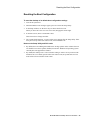
Accessing the Component Drawer ............................................................................................................ 55
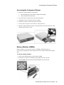
Memory Modules (SIMMs)....................................................................................................................... 55
Cache Memory ......................................................................................................................................... 56
Alpha Processor Upgrade .......................................................................................................................... 57
Intel Processor Upgrade ............................................................................................................................ 59
PCI Option................................................................................................................................................ 61
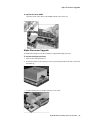
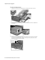
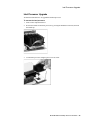
Power Supply............................................................................................................................................ 62
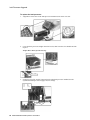
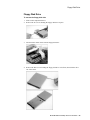
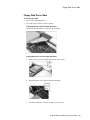
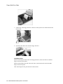
Floppy Disk Drive .................................................................................................................................... 65
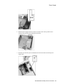
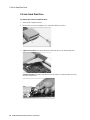
2.5-Inch Hard Disk Drive.......................................................................................................................... 66
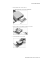
3.5-Inch Hard Disk Drive (Alpha-Based Models)...................................................................................... 68
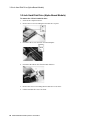
3.5-Inch Disk Drive (Intel-Based Models)................................................................................................. 69
Backplane ................................................................................................................................................. 70
System Board............................................................................................................................................ 71
Battery ...................................................................................................................................................... 73
Speaker..................................................................................................................................................... 74
Floppy Disk Drive Cable .......................................................................................................................... 75
7 Restoring Multia Software
Restoring Multia Software on a Corrupted Desktop .................................................................................. 77
Restoring Intel-Based Models (Multia Version 3.1)............................................................................ 77
Restoring Alpha-Based Models (Multia Version 3.0) ......................................................................... 79
Setting Up Servers for the Remote Maintenance Facility .......................................................................... 80
Configuring a Multia MOP Server ..................................................................................................... 81
Configuring an OpenVMS MOP Server ............................................................................................. 81
Starting the Multia MOP Server ......................................................................................................... 81
Configuring a BOOTP Server ............................................................................................................ 82
v
Starting the Multia BOOTP Server..................................................................................................... 83
Specifying a Multia MOP or TFTP Startup Account .......................................................................... 83
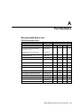
A Part Numbers
Recommended Spares List ........................................................................................................................ 85
Field Replaceable Units ..................................................................................................................... 85
General Recommended Spares ........................................................................................................... 86
Hardware .................................................................................................................................................. 87
Part Numbering Conventions ............................................................................................................. 87
Multia Single System Box.................................................................................................................. 88
Memory Modules ............................................................................................................................... 91
Disk Drives ........................................................................................................................................ 91
Keyboards.......................................................................................................................................... 92
Digital Color Monitors.............................................................................................................................. 92
Cables....................................................................................................................................................... 93
Related Documentation............................................................................................................................. 94
B Pinouts
Bidirectional Parallel Port Pinouts ............................................................................................................ 95
Communications Port Pinouts ................................................................................................................... 96
External SCSI Port Pinouts ....................................................................................................................... 97
Floppy Disk Controller Pinouts ................................................................................................................. 98
Keyboard Port Pinouts .............................................................................................................................. 98
Mouse Port Pinouts ................................................................................................................................... 99
Network Ports Pinouts............................................................................................................................... 99
Thickwire Pinouts (J2) ....................................................................................................................... 99
ThinWire Pinouts (J3) ...................................................................................................................... 100
Twisted Pair (J4) Pinouts.................................................................................................................. 100
Power Port (J10) Pinouts ......................................................................................................................... 101
Video Port (J1) Pinouts ........................................................................................................................... 101
System Board Jumpers (Alpha-Based Models)........................................................................................ 102
System Board Jumpers (Intel-Based Models) .......................................................................................... 103
Index
vi
About This Guide
Audience
This guide is for Digital service personnel and qualified self-maintenance customers.
Purpose
This guide describes how to troubleshoot and service the Multia MultiClient Desktop. The
guide covers Alpha- and Intel-based models:
•
System overview
•
Troubleshooting Alpha-based models
•
Troubleshooting Intel-based models
•
Console commands (Alpha-based models)
•
BIOS Setup utility (Intel-based models)
•
Removing and replacing FRUs
•
Restoring Multia desktops to an intial software state
•
Part numbers and pinouts
Multia MultiClient Desktop Service Information vii
1
Multia System Description
Overview
The Multia MultiClient Desktop is a network-ready device that implements the application
server method of client-server computing. The desktop comes with the Windows NT
Workstation operating system and Multia Base Software preinstalled. Alpha- and Intel-based
models are available.
The desktop provides users with access to Windows, Windows NT, and video terminal
applications on host systems and file servers in a variety of network environments. As
options, users can add access to X window applications and mainframe applications.
The Multia Base Software includes a Configuration Manager that lets a system administrator
centrally manage and configure Multia MultiClient Desktops across a local area network
(LAN) or wide area network (WAN). The CD-ROM in the System Administrator Kit provides
a copy of the base software plus options and Remote Maintenance Facility (RMF) software
for restoring desktops to their initial software state. Administrators can use the CD-ROM to
upgrade and repair desktops.
System Hardware Features
Alpha-Based Models
The VX40 model has a fixed 166 MHz Alpha CPU and fixed 256K cache memory.
The VX41 model has an upgradable 166 MHz Alpha CPU and upgradable 256K cache
memory.
The VX42 model has an upgradable 233 MHz Alpha CPU and upgradable 512K cache
memory.
•
166 MHz or 233 MHz Alpha CPU
•
ZIF socket for CPU upgrades (VX41 and VX42 models)
•
High-performance PCI-based graphics accelerator
•
24 MB memory, expandable to 128 MB
•
ECC memory that supports error detection and correction
•
528 MB or 540 MB hard disk drive (2.5 inch or 3.5 inch)
•
Floppy disk drive (standard on VX41 and VX42 models, optional on the VX40 model)
•
256 KB, 512 KB, and 1MB cache memory options
Multia MultiClient Desktop Service Information 1
Overview
•
Two PCMCIA slots (type 1 or 2)
•
Autosensing PCI-based Ethernet connections: thickwire (10Base5), ThinWire (10Base2),
twisted pair (10BaseT)
•
CD-quality input/output, optional headset and microphone, and built-in speaker
•
Multisynchronous monitor support for 640x480, 1024x768, and 1280x1024 screen
resolutions at 60 Hz to 75 Hz refresh rate, VGA
•
Two serial lines, both with full modem support
•
Bidirectional parallel port
•
Keyboard options
−
LK411 (108 keys, Digital layout)
−
PCXAL (101/102 keys, PC layout)
•
3-button mouse
•
PCI option slot, short card format (on systems with a 2.5-inch hard disk drive)
•
SCSI-2 connector (standard on the VX41 and VX42 models, optional on the VX40
model)
•
Kensington lock-ready
•
Regulatory compliance
Intel-Based Models
The VX51 model provides an upgradable 100 MHz Pentium CPU and upgradable 256K cache
memory.
•
100 MHz Pentium CPU
•
ZIF socket for CPU upgrades
•
High-performance PCI-based graphics accelerator
•
16 MB memory, expandable to 128 MB
•
810 MB or 1.6 GB hard disk drive (2.5 inch or 3.5 inch)
•
Floppy disk drive
•
256 KB and 512 KB asynchronous, sychronous, or synchronous burst cache memory
options
•
Two PCMCIA slots (type 1 or 2)
•
Autosensing PCI-based Ethernet connections: thickwire (10Base5), ThinWire (10Base2),
twisted pair (10BaseT)
•
CD-quality input/output, optional headset and microphone, and built-in speaker
•
Multisynchronous monitor support for 640x480, 1024x768, and 1280x1024 1600x 1200
screen resolutions at 60 Hz to 75 Hz refresh rate, VGA
•
Two serial lines, both with full modem support
•
Bidirectional parallel port
•
Keyboard options
−
LK411 (108 keys, Digital layout)
−
PCXAL (101/102 keys, PC layout)
2 Multia MultiClient Desktop Service Information
Overview
•
3-button mouse
•
PCI option slot, short card format (on systems with a 2.5-inch hard disk drive)
•
SCSI-2 connector
•
Kensington lock-ready
•
Regulatory compliance
Software Features
Multia MultiClient Desktop (Preinstalled Software)
The Multia MultiClient Desktop comes with preinstalled Multia Base Software and the
Windows NT Workstation operating system.
•
Alpha-based models use Multia Base Software Version 3.0 or earlier and the
Windows NT Workstation Version 3.5 operating system
•
Intel-based models use Multia Base Software Version 3.1 and the
Windows NT Workstation Version 3.51 operating system
All models include
•
•
•
•
•
•
•
•
•
User-selectable setup in English, French, German, and Spanish
Application Manager
Configuration Manager
Status application
Terminal emulator
World Wide Web browser
Reference Desk, online help, and tutorial
TrueType PC font support
Communications protocols
− IPX/SPX
− LAN Manager
− NetBEUI
− NetBIOS
− PATHWORKS
− TCP/IP
− DECnet (Multia Version 3.0 and later)
− LAT
− NFT (bundled with Multia X Server option)
Multia System Administrator Kit
The System Administrator Kit provides the Multia for System Administrators CD-ROM for
performing software upgrades and repairs. The CD-ROM includes
•
Multia Base Software
•
Multia software options (Version 3.0 and later), including
−
−
•
Multia X Server
RUMBA for the Mainframe (3270 emulator)
Remote Maintenance Facility (RMF) software for restoring Multia system disks
Multia MultiClient Desktop Service Information 3
Overview
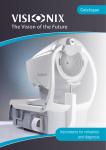
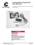
Front View
1.
Stereo audio input
2.
Stereo audio output
3.
Microphone
4.
Stereo headphones
5.
On/off power switch
6.
Floppy disk drive
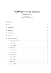
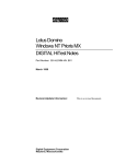
1.
Keyboard connector
2.
Serial port
3.
SCSI-2 connector
4.
PCI slot
5.
Auxiliary power connector
6.
AC input power connector
7.
Kensington lock connector
8.
Mouse connector
9.
PCMCIA type 1 or 2 slot
Rear View
10. Parallel port
11. Twisted pair Ethernet connector
12. ThinWire Ethernet connector
13. PCMCIA type 1 or 2 slot
14. Thickwire Ethernet connector
15. Video connector
16. Thumbscrews
4 Multia MultiClient Desktop Service Information
Specifications
Specifications
System Board
Alpha-Based Models
CPU model
Digital 21066-AA (LCA)
Digital 21068-AA (LCA)
Clock speed
166 MHz
233 MHz
Clock cycle
6.0 ns
4.3 ns
Intel-Based Models
CPU model
Pentium 100 MHz
Clock speed
66 MHz
Memory
Alpha-Based Models
Maximum memory
128 MB
Minimum memory
24 MB
Memory type
JEDEC Standard 36-bit SIMMs in 4 slots,
70 ns or faster
Cache memory
(VX41 and VX42)
256 KB, 512 KB, and 1 MB options
Intel-Based Models
Maximum memory
128 MB
Minimum memory
16 MB
Memory type
JEDEC Standard 36-bit SIMMs in 4 slots,
70 ns or faster
Cache memory
256 KB asynchronous, 256 KB synchronous, 256
KB synchronous burst, and 512 KB options
Power Supply
Rated voltage range
100 V ac to 120 V ac
220 V ac to 240 V ac
Maximum voltage range
88 V ac to 264 V ac
Maximum input current
30 A to 40 A
Output power
74.5 W
Frequency range
47 Hz to 63 Hz
Mechanical
You can place the system box horizontally on a desktop or vertically in its stand.
Multia MultiClient Desktop Service Information 5
Configuration
Horizontal dimensions
317.5 mm (wide) x 317.5 mm (deep) x 71 mm (high)
12.5 inches (wide) x 12.5 inches (deep) x 2.8 inches (high)
Vertical dimensions
127 mm (wide) x 317.5 mm (deep) x 342.9 mm (high)
5.0 inches (wide) x 12.5 inches (deep) x 13.5 inches (high)
Weight
5.45 kg (12 lb)
Environment
Operating
Nonoperating
Temperature
0° C to 40° C
32° F to 104° F
-40° C to 66° C
-40° F to 151° F
Relative humidity
10% to 90%
5% to 95%
Maximum wet bulb
28° C
82° F
46° C
115° F
Minimum dew point
2° C
36° F
–
–
Maximum altitude
2.4 km
8000 ft
4.9 km
16,000 ft
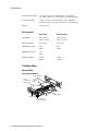
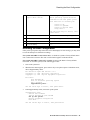
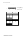
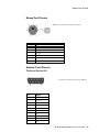
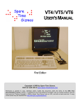
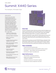
Configuration
System Box
Alpha-Based Models
Floppy Disk Drive
3.5-Inch
Hard Disk Drive
or PCI Option
2.5-Inch
Hard Disk
Drive
CPU
SIMMs
Cache
SIMM
PCMCIA Slots
SCSI-2 Connector
(Optional on VX40)
6 Multia MultiClient Desktop Service Information
System Board
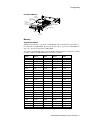
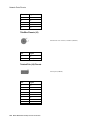
Configuration
Intel-Based Models
3.5-Inch
Hard Disk
Drive or
PCI Option
2.5-Inch
Hard Disk
Drive
Floppy
Disk Drive
CPU
Cache SIMM
SIMMs
System Board
PCMCIA Slots
SCSI-2
Connector
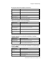
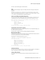
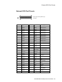
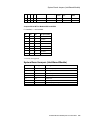
Memory
Alpha-Based Models
SIMMs are used in pairs. You can use 12 MB SIMMs only on models VX41 and VX42. To
be recognized as 12 MB SIMMs, they must be in slots 0 and 1. If you use 12-MB SIMMs in
slots 2 or 3, they are recognized as 8 MB SIMMs.
You can use 64 MB SIMMs if they meet the JEDEC standard and have a height of 1.5 inches.
Currently, Digital’s 64 MB SIMM does not fit in the system box.
Slot 0
Slot 1
Slot 2
Slot 3
Total
4 MB
4 MB
8 MB
8 MB
24 MB
12 MB
12 MB
8 MB
8 MB
16 MB
16 MB
4 MB
12 MB
24 MB
8 MB
8 MB
32MB
4 MB
16 MB
16 MB
40 MB
12 MB
8 MB
8 MB
40 MB
32 MB
8 MB
8 MB
16 MB
16 MB
48 MB
12 MB
12 MB
16 MB
16 MB
56 MB
16 MB
16 MB
16 MB
16 MB
64 MB
32 MB
32 MB
4 MB
4 MB
32 MB
32 MB
72 MB
8 MB
8 MB
32 MB
32 MB
80 MB
12 MB
12 MB
32 MB
32 MB
88 MB
16 MB
16 MB
32 MB
32 MB
96 MB
32 MB
32 MB
32 MB
32 MB
128 MB
64 MB
64 MB
4 MB
4 MB
64 MB
64 MB
136 MB
8 MB
8 MB
64 MB
64 MB
144 MB
12 MB
12 MB
64 MB
64 MB
152 MB
16 MB
16 MB
64 MB
64 MB
160 MB
32 MB
32 MB
64 MB
64 MB
192 MB
64 MB
64 MB
64 MB
64 MB
256 MB
64 MB
128 MB
Multia MultiClient Desktop Service Information 7
Configuration
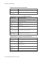
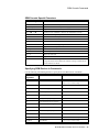
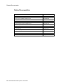
Intel-Based Models
You can use 64 MB SIMMs if they meet the JEDEC standard and have a height of 1.5 inches.
Currently, Digital’s 64 MB SIMM does not fit in the system box.
Slot 0
Slot 1
Slot 2
Slot 3
Total
4 MB
4 MB
8 MB
8 MB
24 MB
8 MB
8 MB
8 MB
8 MB
32 MB
16 MB
16 MB
4 MB
4 MB
16 MB
16 MB
40 MB
8 MB
8 MB
16 MB
16 MB
48 MB
16 MB
16 MB
16 MB
16 MB
64 MB
32 MB
32 MB
4 MB
4 MB
32 MB
32 MB
72 MB
8 MB
8 MB
32 MB
32 MB
80 MB
16 MB
16 MB
32 MB
32 MB
96 MB
32 MB
32 MB
32 MB
32 MB
128 MB
64 MB
64 MB
32 MB
64 MB
128 MB
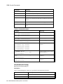
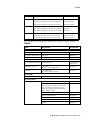
Options
Multia
System Box
Part Number
Suffix
Floppy Disk
Drive
Hard Disk
Drive
PCI
PCMCIA
N
Can be added
Can be added
Can be added
Can be added
F
Included
Can be added
Can be added
Can be added
F2
Included
2.5 inch included
Can be added
Can be added
F3
Included
3.5 inch included
Not available*
Can be added
∗
The PCI option is not available in this configuration, because a 3.5-inch hard disk drive
occupies the space allocated for a PCI board.
8 Multia MultiClient Desktop Service Information
2
Troubleshooting Alpha-Based Models
Troubleshooting Overview
Gathering information is the first action to perform when troubleshooting. Use the site log to
review the system's service history. Ask the user or customer contact the following questions:
•
What first alerted the user to the problem?
•
Were there any recent changes or upgrades to the operating system, firmware, or
application software?
•
What symptoms did the user notice? Ask about any unusual sounds or smells.
•
Did the user make any initial troubleshooting efforts? What were the results?
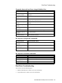
After you collect initial information on the problem, use this table to locate the
troubleshooting section that addresses your problem:
If you have this problem...
Go to...
The system box fails to power up.
Power System Troubleshooting (page 10)
The system box powers up, but nothing is Power System Troubleshooting (page 10)
displayed on the monitor.
The system box powers up, but fails to
boot.
Console Troubleshooting (page 12)
The monitor displays a crash dump.
Machine Checks (page 12)
The system hangs while displaying the
Setting console to boot
mode message or hangs after replacing
the battery.
Battery Problems (page 13)
The system boots and the blue screen
appears, but fails to boot the hard drive.
Boot Problems (page 13)
You cannot access network applications.
The SRM console, and see the Network Problems
section (page 14)
The system is slow or displays less
memory than you know is installed.
The SRM console, and see the Memory Problems
section (page 15)
The floppy diskette is inaccessible for
reading or writing during normal
operation (Windows NT operating
system running).
The SRM console, and see the Floppy Drive Problems
section (page 15)
Your system fails to boot and you cannot
solve the boot problems.
The SRM console, and see the SCSI Drive Problems
section (page 16)
Multia MultiClient Desktop Service Information 9
Troubleshooting Equipment
Troubleshooting Equipment
Be sure to have the following equipment available when troubleshooting:
•
TW, thin, AUI loopback connectors (for network problems)
•
FAT-formatted floppy diskette
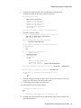
Troubleshooting
During a normal power-up sequence, the following occurs:
•
The green LED on the power switch at the front of the system box is on.
•
The diagnostic LED between the serial port and twisted-pair connector on the back of the
system box displays a list of sequence codes (page 11).
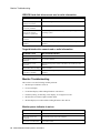
To address power system problems, you can check the power switch, diagnostic LED, and
power port pinouts. The Power Systems Problems table gives common symptoms of power
problems and recommends actions.
Power System Problems
Symptom
Recommended Action
The power switch LED is off. 1.
Make sure the power switch on the front of the system box is
pushed in.
2.
Make sure the system is plugged in and the power source is
operating. Check the ac cord.
3.
If the switch still does not work, replace the power supply.
(The switch is hardwired to the power supply.)
1.
The diagnostic LED on the
back of the system box is off. 2.
If the LED never goes on, check the power supply.
For VX40 models, if the LED goes on but does not sequence,
replace the system board (page 71).
On VX41 and VX42 models, the SROM does not flash on
powerup.
The power switch LED is on, 1.
but the monitor display is
blank.
2.
Make sure the power switch on the front of the system box is
pushed in.
Make sure the video controller cable is properly connected.
3.
Check the SROM LED codes (page 11).
4.
Make sure power is present at the system board. See Power
Port Pinouts (page 100) for more information.
Initialization and Power-On Self-Test Errors
The diagnostic LED on the back of the system box indicates the symptom of any problem that
occurs during initialization or the power-on self-test (POST).
When you turn on the system, the SROM initializes the CPU, core logic, and memory.
During power-on, the CPU loads the POST from the SROM. Typically, the POST reports
errors that prevent the console from booting.
During power-on, if the system fails a test, the LED flashes to indicate that the test failed. On
the VX40 model, the diagnostic LED also flashes at the beginning of each self-test.
10 Multia MultiClient Desktop Service Information
Initialization and Power-On Self-Test Errors
See the SROM LED code table for a list of SROM codes, descriptions, and recommended
actions.
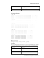
SROM LED Codes
The diagnostic LED on the system box flashes at power-up. On the VX40 model, the LED
also flashes once (briefly) for each sequence number displayed. If the SROM code completes
testing without errors, the LED remains off. If an error occurs, the LED flashes a
hexadecimal code from the following table:
Code
Description
Recommended Action
F
Failed while sizing memory.
For VX41 and VX42 models, first replace the cache
SIMM (page 56). If this does not fix the problem,
continue with the recommended action for VX40
models.
For VX40 models, replace memory modules
(SIMMs) (page 55) until no failure occurs. If
replacing the SIMMs does not fix the problem,
replace the system board (page 71).
E
Failed while configuring
memory.
For VX41 and VX42 models, first replace the cache
SIMM (page 56). If this does not fix the problem,
continue with the recommended action for VX40
models.
For VX40 models, replace memory modules
(SIMMs) (page 55) until no failure occurs. If
replacing the SIMMs does not fix the problem,
replace the system board (page 71).
D
Testing for mapped out MCRs.
For VX41 and VX42 models, first replace the cache
SIMM (page 56). If this does not fix the problem,
continue with the recommended action for VX40
models.
For VX40 models, replace memory modules
(SIMMs) (page 55) until no failure occurs. If
replacing the SIMMs does not fix the problem,
replace the system board (page 71).
B
Configured memory okay.
For VX41 and VX42 models, first replace the cache
SIMM (page 56). If this does not fix the problem,
continue with the recommended action for VX40
models.
For VX40 models, replace memory modules
(SIMMs) (page 55) until no failure occurs. If
replacing the SIMMs does not fix the problem,
replace the system board (page 71).
A
Testing 8M memory with
internal data cache OFF and
backup cache OFF.
For VX41 and VX42 models, first replace the cache
SIMM (page 56). If this does not fix the problem,
continue with the recommended action for VX40
models.
For VX40 models, replace memory modules
(SIMMs) (page 55) until no failure occurs. If
replacing the SIMMs does not fix the problem,
replace the system board (page 71).
9
Testing 8M memory with
internal data cache OFF and
backup cache ON.
For model VX40, replace the system board (page
71).
For models VX41 and VX42, first replace the cache
Multia MultiClient Desktop Service Information 11
Console Troubleshooting
Code
Description
Recommended Action
SIMM (page 56). If replacing the cache SIMM does
not fix the problem, replace the system board (page
71).
8
Testing 8M memory with
internal data cache ON and
backup cache OFF.
Replace the system board (page 71).
7
Testing 8M memory with
internal data cache ON and
backup cache ON.
For model VX40, replace the system board (page
71).
For models VX41 and VX42, first replace the cache
SIMM (page 56). If replacing the cache SIMM
does not fix the problem, replace the system board
(page 71).
6
Failed to find SIO while scanning Replace the backplane (page 69). If a new
PCI ID lines.
backplane does not fix the problem, replace the
system board (page 71).
5
Testing PCI data path using SIO.
Replace the backplane (page 69). If a new
backplane does not fix the problem, replace the
system board (page 71).
4
Testing flash ROM header.
(Checks manufacturing code.)
Replace the system board (page 71).
3
Failed flash ROM size field out
of range.
Replace the system board (page 71).
2
Testing flash ROM checksum
(after loaded data).
Replace the system board (page 71).
1
Done with flash ROM load
(either ROM0 or ROM2).
No action.
0
Jumping to SRM console prompt. No action.
If the SROM code is unable to load the Multia SRM
console from flash ROM, or there is a checksum
error after loading the flash code, then it attempts to
load ARC from flash ROM. If SROM cannot load
ARC, then an error code flashes on the back of the
system box.
Console Troubleshooting
The Multia MultiClient Desktop contains two console firmware systems. The ARC console
supports the Windows NT system and the SRM console is the Multia diagnostics console.
The SRM console in the flash ROM contains manufacturing diagnostics.
If the system powers up but fails to boot and displays a crash dump, see the Machine Checks
section.
Machine Checks
Symptom
Recommended Action
The system powers up but
fails to boot, and a crash
dump is displayed on your
monitor.
For VX41 and VX42 models, first replace the cache SIMM (page
56). If this does not fix the problem, continue with the
recommended action for VX40 models.
For VX40 models, replace memory modules (SIMMs) (page 55)
12 Multia MultiClient Desktop Service Information
Console Troubleshooting
Symptom
Recommended Action
until no failure occurs. If replacing the SIMMs does not fix the
problem, replace the system board (page 71).
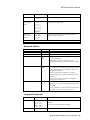
Battery Problems
Symptom
Recommended Action
The system hangs, displaying Replace the battery (page 73).
the message Setting
console to boot mode.
The system hangs after
replacing the battery.
Replace the system board (page 71).
Boot Problems
Symptom
Recommended Action
The system cannot find the
boot device.
1.
Check the system configuration for correct device parameters.
2.
Use the ARC console to display the available boot devices.
First, from the Boot menu, select the Supplementary menu...,
then select list available boot devices. Verify that the target
boot device is listed.
3.
If the target boot device is not listed, try resetting the boot
configuration (page 41).
1.
Check and set the environment variables, if necessary.
2.
Check that the SCSI cable in the system box is properly
connected.
1.
Make sure cables are oriented properly and connected.
2.
Check for bent pins.
3.
Check all the SCSI devices for incorrect or conflicting IDs.
Refer to the device's documentation.
4.
Check the SCSI bus termination. The SCSI bus must be
terminated at the last internal and the last external SCSI
peripherals. The last internal SCSI device automatically
provides termination.
Environment variables are
incorrectly set.
(For example, configuration
settings may be lost if the
battery or system board were
replaced.)
The target boot device is not
listed in the ARC's list
available boot
devices command, due to
a SCSI bus problem.
The external SCSI cabling must be less than 9 feet long.
If no external SCSI cable or devices are plugged into the rear
SCSI connector, the external portion is automatically
terminated. If a SCSI cable is plugged in, then the automatic
termination is disabled and the SCSI device must use a
terminator.
Multia MultiClient Desktop Service Information 13
Console Troubleshooting
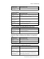
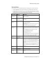
Network Problems
On power-up, the Ethernet LAN controller driver autosenses which of the three ports is
connected. The default order of network detection is
1.
Twisted pair
2.
ThinWire
3.
Thickwire
If there is no network connection, the LAN controller defaults to thickwire. If you change a
network connection while the system is running, you have to reboot.
Symptom
Recommended Action
You cannot access network
applications.
1.
Go to the SRM console.
2.
At the >>> prompt, enter SHOW DEVICE
You should see the following display:
3.
dka0.0.6.0
DKA0
dva0.0.0.0.1
DVA0
TOSHIBA MK232FB A156
ewa0.0.0.11.0 EWA0
08-00-2B-E2-C0-3B
pka0.7.0.6.0
SCSI Bus ID 7
PKA0
If EWA0 is not in the list of devices, replace the system board
(page 71).
If EWA0 is in the list of devices, install JW thin AUI loopback
connectors, and enter the following commands:
>>> SET EWA0_MODE TWISTED
>>> TUNET
4.
Wait 30 seconds.
If a failure occurs, replace the system board (page 71).
If no failure occurs, continue with step 5.
5.
Enter the following command:
>>> EWA0_MODE AUI
6.
Wait 30 seconds.
If a failure occurs, replace the system board (page 71).
If no failure occurs, continue with step 7.
7.
Enter the following command:
>>> SET EWA0_MODE THIN
8.
Wait 30 seconds.
If a failure occurs, replace the system board (page 71).
If no failure occurs, continue with step 9.
9.
Enter the following command:
>>> SET EWA0_MODE AUTO
14 Multia MultiClient Desktop Service Information
Console Troubleshooting
Symptom
Recommended Action
Caution
Be sure to perform step 9. If you do not set EWA0_MODE to
AUTO, all future Multia functions will fail.
10. Power down the Multia system.
11. Remove loopback connectors.
12. Connect the Multia system to the network.
13. Power up the Multia system.
14. At the >>> prompt, enter the following command:
>>> TUNET
15. Wait 30 seconds.
If a failure occurs, it is due to a problem with the building
network or the cable between the Multia system and the
building network.
If no failure occurs, the network is operating properly.
Memory Problems
Symptom
Recommended Action
Various problems may
indicate a problem with
memory, such as the system
is slow or the system
displays less memory than
you know is installed.
1.
Go to the SRM console.
2.
At the >>> prompt, enter the following command:
>>> MEMORY
If no error occurs within 30 seconds, there are no problems
with memory.
3.
If an error occurs, replace the cache SIMM (page 56). If
replacing the cache SIMM does not fix the problem, replace
each memory module (SIMM) (page 55), one at a time, until
the error is corrected. Make sure to use 72-pin, 70-nanosecond,
JEDEC standard, 36-bit SIMMs.
4.
If the error continues to occur after replacing the SIMMs,
replace the system board (page 71).
Floppy Drive Problems
Symptom
Recommended Action
The floppy diskette is
inaccessible for reading or
writing during normal
operation (Windows NT
operating system running).
1.
Go to the SRM console.
2.
At the >>> prompt, enter SHOW DEVICE
You should see the following display:
dka0.0.6.0
DKA0
TOSHIBA MK232FB A156
Multia MultiClient Desktop Service Information 15
Console Troubleshooting
Symptom
Recommended Action
dva0.0.0.0.1
3.
DVA0
ewa0.0.0.11.0 EWA0
08-00-2B-E2-C0-3B
pka0.7.0.6.0
SCSI Bus ID 7
PKA0
If dva0 is not in the list of devices, first replace the floppy
drive (page 65), then replace the cable.
If dva0 is in the list of devices, install a FAT-formatted floppy
diskette and enter the following command:
>>> FLOPPY
4.
If an error occurs, try replacing each of the following parts in
order, until the error is fixed:
a. Floppy disk drive cable (page 74)
b. Floppy disk drive (page 65)
c. System board (page 71)
SCSI Drive Problems
Symptom
Recommended Action
Your system fails to boot,
and boot problems cannot be
solved.
1.
Go to the SRM console.
2.
At the >>> prompt, enter SHOW DEVICE
You should see the following display:
3.
dka0.0.6.0
DKA0
dva0.0.0.0.1
DVA0
TOSHIBA MK232FB A156
ewa0.0.0.11.0 EWA0
08-00-2B-E2-C0-3B
pka0.7.0.6.0
SCSI Bus ID 7
PKA0
If PKA0 is not in the list of devices, then the SCSI chip is not
being seen.
Remove the external SCSI device connection and type the
SHOW DEVICE command again.
4.
If the PK device is still not in the list of devices, replace the
backplane (page 69).
Enter the SHOW DEVICE command again.
5.
If PKA0 is still not in the list of devices, replace the system
board (page 71).
6.
If PKA0 is in the list, but DKA0 is not, replace the hard drive:
2.5-inch (page 66)
3.5-inch, Alpha-based model (page 67)
3.5-inch, Intel-based model (page 69)
Enter the SHOW DEVICE command again.
7.
16 Multia MultiClient Desktop Service Information
If DKA0 is still not in the list of devices, replace the SCSI
drive.
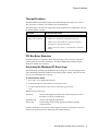
Thermal Problems
Thermal Problems
The Multia MultiClient Desktop operates in an ambient temperature range of 0° to 40° C.
The system box is cooled by one automatic speed-controlled fan.
The power supply varies the fan voltage based on the feedback from a temperature sensor in
the fan and speaker assembly.
Symptom
Recommended Action
Intermittent problems
resulting from overheating.
1.
Make sure the airflow path is clear.
2.
Make sure no materials are blocking the input grill.
3.
Make sure the cables inside the system box are properly
dressed and not impeding the airflow.
4.
Make sure the fan is turning. You should hear it and detect
airflow.
PCI Bus Error Detection
Not all PCI devices are required to detect and report parity errors, but all are required to
generate parity on all of their transactions. The Multia MultiClient Desktop has parity
disabled by default; do not enable it.
Accessing the Windows NT Event Logs
The Windows NT operating system maintains an event log file. The event logging service
starts automatically when the Windows NT operating system is started. The Event Viewer
lets you view and manage the event logs.
To start the Event Viewer
1.
Press Ctrl + Esc to display the Task List.
2.
In the New Task box, enter eventvwr.exe and choose Run.
3.
Use the Log menu of the Event Viewer to select the log you need to
view.
Windows NT uses three logs:
System log
Tracks events logged by Windows NT system components, such as
the failure of a driver to load properly.
Application log
Tracks events logged by applications.
Security log
Tracks changes to the security system and identifies possible
security breaches.
For more information, see the Event Viewer chapter in the Microsoft Windows NT System
Guide or use the Event Viewer's online help on the Multia desktop.
Multia MultiClient Desktop Service Information 17
3
Troubleshooting Intel-Based Models
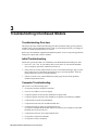
Troubleshooting Overview
This chapter provides initial troubleshooting procedures and tables listing specific problems,
probable causes, and recommended actions to take if your desktop fails after you configure it
or after you install optional hardware or software.
Refer to the documentation supplied with additional options if you are experiencing problems
with specific options that you have installed.
Initial Troubleshooting
Follow these general procedures to troubleshoot your Multia MultiClient Desktop for Intel.
•
Press Ctrl + Alt + Del. If your desktop fails to boot, turn it off, wait until all hard disk
drives completely spin down, and then turn it back on.
•
If the power-on self-test (POST) detects an error, refer to POST Messages (page 25) and
Beep Codes (page 27) and take the appropriate steps to correct the problem. After the
problem has been resolved, restart the computer.
•
If there are POST errors, run the BIOS Setup utility (page 44) and fix the problems
identified by the POST errors.
Computer Troubleshooting
This section covers the following topics:
•
No response when the computer is turned on.
•
Power is on, but there is no screen display.
•
Computer operates incorrectly after installation of option board.
•
Computer operates incorrectly after installation of optional system memory (SIMMs).
•
Computer fails to retain setup information.
•
Computer does not boot from an IDE hard disk drive.
•
Computer does not recognize an external SCSI device.
(If you have both IDE and SCSI hard disk drives installed, your computer uses the IDE
hard disk drive as the boot device.)
•
Computer does not boot from a target diskette drive.
•
No response to keyboard commands.
•
No response to mouse commands.
18 Multia MultiClient Desktop Service Information
Computer Troubleshooting
No response when the computer is turned on.
Probable Cause
Recommended Action
The computer is not plugged
in.
Turn off the computer, plug it in, and then turn it back on again.
No power is at the wall
outlet.
Use another wall outlet.
The system board failed.
Replace the system board (page 71).
The system board jumpers
are incorrectly set.
Set all appropriate jumpers.
The power supply failed.
Replace the power supply (page 62).
Power is on, but there is no screen display.
Probable Cause
Recommended Action
The brightness and contrast
Adjust the brightness and contrast controls.
controls are not correctly set.
The monitor is off.
Turn on the monitor.
The monitor-off timer has
shut off the monitor.
Press the Shift key to reactivate the monitor.
The monitor cable is
incorrectly installed.
Check all monitor connections.
The onboard video controller Replace the system board (page 71).
failed.
The monitor failed.
Replace the monitor.
Computer operates incorrectly after installation of optional
expansion board.
Probable Cause
Recommended Action
The expansion board is
installed incorrectly.
Remove the expansion board and reinstall.
The expansion board failed.
Remove the expansion board and reboot. If the computer boots
without errors, replace the expansion board.
Computer operates incorrectly after installation of optional system
memory (SIMMs).
Probable Cause
Recommended Action
The SIMMs are installed
incorrectly.
Remove the SIMMs and reinstall (page 55).
The SIMMs have failed.
Remove the SIMMs and reinstall.
Make sure slots (0 and 1) or (2 and 3) are filled with the correct
SIMM size, speed, and type.
Replace the SIMMs.
Multia MultiClient Desktop Service Information 19
Computer Troubleshooting
Computer fails to retain setup information.
Probable Cause
Recommended Action
The computer battery has
failed.
Replace the computer battery (page 73).
The CMOS clear jumper
(W6) is enabled.
Disable the CMOS clear jumper (W6).
Computer does not boot from an IDE hard disk drive.
Probable Cause
Recommended Action
The IDE drive type incorrect. Run the BIOS Setup utility to identify the correct drive type. See
the drive type label on the drive or consult the drive documentation.
The cables are loose.
Secure all cable connections.
The onboard IDE interface is Run the BIOS Setup utility and set the IDE Hard Disk Drives option
disabled.
to Enabled.
The hard disk boot sector is
missing.
Restore the Multia desktop to its inital software state (page 77).
Replace the disk.
Operating system software is Install the appropriate operating system.
not installed on the IDE hard
disk drive.
Format the IDE hard disk drive or partition the IDE hard disk drive
The IDE hard disk drive is
not correctly formatted or the using the supplied operating system software.
requested partition does not
exist.
There is no software on the
requested partition.
Install software on the requested partition.
Computer does not recognize an external SCSI device.
Probable Cause
Recommended Action
The SCSI device jumpers are Refer to the supplied SCSI device kit installation instructions.
incorrectly set.
A SCSI ID conflict exists.
Refer to the supplied SCSI device kit installation instructions on
setting SCSI IDs.
The terminating resistors are
not removed from the SCSI
device.
Remove the terminating resistors. Refer to the supplied kit
installation instructions.
The SCSI cable is not
terminated.
Terminate each end of the SCSI cable.
The SCSI device is not
plugged in.
Check the power and SCSI cables.
The SCSI cable is loose.
Secure all cable connections.
20 Multia MultiClient Desktop Service Information
Disk Drive Troubleshooting
Computer does not boot from a target diskette drive.
Probable Cause
Recommended Action
The onboard diskette
controller is disabled.
Run the BIOS Setup utility and set the diskette controller option to
"Enabled."
The diskette drive is not
enabled.
Run the BIOS Setup utility to enable the diskette drive.
The diskette drive type is
incorrect.
Make sure the drive ID is correctly set (refer to the documentation
supplied with your diskette drive).
The diskette boot option is
disabled.
Run the BIOS Setup utility and set Boot From Diskette A to
Enabled.
The diskette might not be
bootable.
Use a bootable diskette.
The diskette does not contain Insert a diskette with the correct startup files.
startup files.
The diskette drive is empty.
Insert a diskette that contains an operating system.
The diskette is worn or
damaged.
Try another diskette.
The cables are loose.
Secure all cable connections.
No response to keyboard commands.
Probable Cause
Recommended Action
The keyboard is not
connected.
Power down the computer and connect the keyboard.
The keyboard is connected to Power down the computer and connect the keyboard to the keyboard
the mouse port.
port.
The computer operation is
halted.
Reboot the computer.
No response to mouse commands.
Probable Cause
Recommended Action
The mouse is not connected.
Power down the computer and connect the mouse.
The mouse is connected to
the keyboard port.
Power down the computer and connect the mouse to the mouse port.
Computer operation is halted. Reboot the computer.
Disk Drive Troubleshooting
This section covers the following topics:
•
IDE/SCSI hard disk drive cannot read or write information.
•
Target diskette drive cannot read or write information.
Multia MultiClient Desktop Service Information 21
Monitor Troubleshooting
IDE/SCSI hard disk drive cannot read or write information.
Probable Cause
Recommended Action
The disk drive jumper
settings are incorrect.
Refer to the supplied kit installation instructions.
The cables are loose or
incorrectly installed.
Make sure all cables are correctly installed.
The IDE/SCSI hard disk
drive is not correctly
formatted or partitioned.
Format and partition the drive as required using the supplied
operating system.
The IDE drive type is
incorrect.
Run the BIOS Setup utility to identify the correct drive type.
The onboard IDE interface is Run the BIOS Setup utility and set the IDE controller option to
disabled.
Enabled.
Target diskette drive cannot read or write information.
Probable Cause
Recommended Action
The diskette is not formatted. Format the diskette.
The diskette is worn or
damaged.
Try another diskette.
The diskette is writeprotected.
Slide the write-protect switch so the hole is not visible (3.5-inch
diskette).
The diskette drive is empty.
Insert a diskette.
The onboard diskette
controller is disabled.
Run the BIOS Setup utility and set the diskette controller option to
Enabled.
Monitor Troubleshooting
This section covers the following monitor problems:
•
Monitor power indicator is not on.
•
No screen display.
•
No monitor display while loading Windows video drivers.
•
Distorted, rolling, or flickering screen display, or wrong/uneven color.
•
Monitor fails to switch to high-resolution mode.
•
Monitor display not centered while loading Windows video drivers.
Monitor power indicator is not on.
Probable Cause
Recommended Action
The monitor is turned off.
Turn on the monitor.
The power cord is not
connected.
Connect the power cord to the computer.
No power is at wall outlet.
Use another outlet.
22 Multia MultiClient Desktop Service Information
Monitor Troubleshooting
Probable Cause
Recommended Action
The monitor-off timer shut
off the monitor.
Press the Shift key to reactivate the monitor.
No screen display.
Probable Cause
Recommended Action
A configuration error has
occurred.
Run the BIOS Setup utility to configure the computer for VGA
operation.
The monitor power cable is
loose or disconnected.
Secure or reattach the monitor power cable.
The monitor brightness and
contrast controls are
incorrectly set.
Adjust the monitor brightness and contrast controls.
The monitor-off timer shut
off the monitor.
Press the Shift key to reactivate monitor.
The onboard video controller Replace the system board (page 71).
failed.
No monitor display while loading Windows video drivers.
Probable Cause
Recommended Action
The monitor type is
incorrectly set.
Set the correct monitor type, using the appropriate utility. Also see
any appropriate README files.
The wrong Windows driver
is loaded.
Load the correct video driver.
Distorted, rolling, or flickering screen display, or wrong/uneven
color.
Probable Cause
Recommended Action
The monitor is incorrectly
adjusted.
Adjust the monitor accordingly.
The monitor signal cable is
incorrectly installed.
Straighten any bent connector pins and reconnect the monitor signal
cable.
Monitor fails to switch to high-resolution mode.
Probable Cause
Recommended Action
Appropriate high-resolution
video drivers are not
installed or are installed
incorrectly.
Correctly install all appropriate high-resolution video drivers. See
the documentation supplied with your monitor.
The video controller and/or
monitor does not support the
high-resolution mode that
has been selected.
Check the system's README.TXT file and any information
supplied with the monitor to determine an appropriate video
resolution mode. Correctly set the video-resolution mode and
install the appropriate video drivers.
Multia MultiClient Desktop Service Information 23
Network Interface Troubleshooting
Monitor display not centered while loading Windows video drivers.
Probable Cause
Recommended Action
The monitor type is
incorrectly set.
Set the correct monitor type using the appropriate utility.
The monitor display is misadjusted.
Adjust the display using the monitor's adjustment controls.
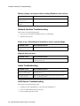
Network Interface Troubleshooting
This section covers the following topics:
•
Power is on, LAN address is installed on server; system hangs.
•
Network does not start.
Power is on, LAN address is installed on server; system hangs.
Probable Cause
Recommended Action
The correct software is not
installed on the server.
Contact your system administrator or network coordinator.
Network does not start.
Probable Cause
Recommended Action
The network cable is loose.
Secure the cable. Ensure that no more than one Ethernet cable is
connected at one time.
Audio Troubleshooting
Probable Cause
Recommended Action
The sound, MIDI, or mixer
drivers are not installed.
Check the error messages for the necessary drivers, and install the
necessary drivers.
The cables are loose or not
properly connected.
Make sure the speaker and microphone plugs are in the correct
jacks. Reconnect the cables.
SCSI Device Troubleshooting
This section covers the following topics:
•
Cannot access the CD-ROM drive. Error message reading drive x.
•
Power is on but indicator shows no activity.
•
Disc is spinning, but drive is idle.
24 Multia MultiClient Desktop Service Information
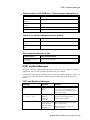
POST and Boot Messages
Cannot access the CD-ROM drive. Error message reading drive x.
Probable Cause
Recommended Action
The device drivers are not
installed.
Install the correct device drivers.
The CD-ROM drive is empty Insert a disc.
(no disc).
The tray is open.
Close the tray.
A SCSI ID conflict exists.
Check that the jumpers are properly set.
Power is on, but the indicator shows no activity.
Probable Cause
Recommended Action
The tray is empty (no disc)
or open.
Insert a disc and close the tray.
The cable connections are
loose.
Make sure the cables are correctly connected.
Disc is spinning but drive is idle.
Probable Cause
Recommended Action
The application software is
not running.
Run the application software.
POST and Boot Messages
The power-on self test (POST) displays messages to alert you to errors in hardware, software,
and firmware or to provide operating information about your computer.
Each time the POST displays a message on your screen, the computer's speaker beeps twice. If
an error occurs before the monitor is initialized, specific beep codes sound to alert you to a
problem.
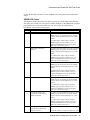
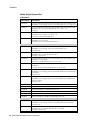
POST and Boot Error Messages
Message
Problem
Solution
Diskette drive A
error
The diskette drive
failed.
Run the BIOS Setup utility. Check all
connections. If the problem persists,
replace the defective diskette drive, the
drive cable, or both.
Extended RAM Failed
at offset: nnnn
Extended memory
failed or is
configured
incorrectly.
Make sure SIMMs are installed
correctly. If the problem persists,
replace defective SIMMs.
Failing Bits: nnnn
nnnn is a map of the
bits at the RAM
address that failed
the memory test.
Run the BIOS Setup utility and restore
all to original values.
If the problem persists, replace the
defective memory.
Multia MultiClient Desktop Service Information 25
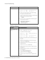
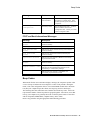
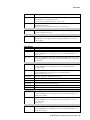
POST and Boot Messages
Message
Problem
Solution
Fixed Disk 0 Failure
Fixed Disk 1 Failure
Fixed Disk Controller
failure
The hard disk drive,
drive controller, or
both failed.
Run the BIOS Setup utility. Check all
connections. If the problem persists,
replace the defective hard disk drive
and/or controller.
Incorrect Drive A
type - run SETUP
Diskette drive A is
not correctly
identified in the
BIOS Setup utility.
Run the BIOS Setup utility and
properly identify diskette drive A.
Invalid NVRAM media
type
NVRAM access
failed.
Run the BIOS Setup utility and restore
all settings to original values. If the
problem persists, replace the defective
component.
Keyboard controller
error
Keyboard error
Keyboard locked Unlock key switch
The keyboard,
keyboard controller,
or both failed.
Check the keyboard connection. If the
connection is secure, the keyboard or
keyboard controller might have failed.
If the problem persists, replace the
defective keyboard, the controller, or
both.
Monitor type does not
match CMOS - Run
SETUP
The monitor type is
specified
incorrectly.
Run the BIOS Setup utility and set the
correct monitor type.
Operating system not
found
The operating
system cannot be
found on drive A or
drive C.
Run the BIOS Setup utility and
correctly identify drive A or drive C.
Press F1 to resume,
F2 to Setup
This message
appears after any
recoverable error
message.
Press F1 to reboot or F2 to enter the
BIOS Setup utility to make any
necessary changes.
Real time clock error
The real-time clock
failed the BIOS test.
Replace real-time clock and then run
the BIOS Setup utility to restore
previous configuration information.
Shadow RAM Failed at
offset: nnnn
Shadow RAM
failed.
Run the BIOS Setup utility and disable
failed shadow memory region.
System battery is
dead - Replace and
run SETUP
The battery or realtime clock failed.
Replace the battery (page 73) and then
run the BIOS Setup utility to restore
previous configuration information.
System cache error Cache disabled
RAM cache failed.
Run the BIOS Setup utility and restore
all settings to original values. If the
problem persists, replace the defective
cache memory (page 56).
System CMOS checksum
bad - run SETUP
System RAM failed at
offset: nnnn
The battery failed.
Replace the battery (page 73).
System RAM
failed.
Run the BIOS Setup utility and restore
all settings to original values. If the
problem persists, replace the defective
memory.
26 Multia MultiClient Desktop Service Information
Correctly install the operating system.
Refer to the supplied operating system
documentation.
Beep Codes
Message
Problem
Solution
System timer error
The computer's
timer test failed.
Run the BIOS Setup utility and restore
all settings to original values. If the
problem persists, replace the defective
component.
Invalid system
configuration
The battery failed.
Run the BIOS Setup utility . From the
Advanced Menu, choose reset
configuration data. Choose yes to clear
system configuration data.
POST and Boot Informational Messages
Message
Description
nnnn Cache SRAM
Passed
Indicates how much cache memory (nnnn kilobytes)
tested successfully.
Entering SETUP
BIOS Setup utility runs.
nnnn Extended RAM
Passed
Indicates how much extended memory (nnnn kilobytes)
tested successfully.
nnnn Shadow RAM
passed
Indicates how much shadow RAM (nnnn kilobytes)
tested successfully.
System BIOS shadowed
Indicates that your computer’s BIOS was successfully
copied to shadow RAM.
nnnn System RAM
passed
Indicates how much system RAM (nnnn kilobytes)
tested successfully.
UMB upper limit
segment address: nnnn
Displays the address of the upper limit of UMB,
indicating the released BIOS segments that can be
reclaimed by a virtual memory manager.
Video BIOS shadowed
Indicates that your computer’s video BIOS was
successfully copied to shadow RAM.
Beep Codes
When POST finds an error and cannot display a message, the computer's speaker emits
a series of beeps to indicate the error and places a value in I/O port 80h. During the
POST, if the video configuration fails or if an external ROM module fails a checksum
test, then your computer beeps three times (one long beep, and two short beeps).
The following table lists other fatal errors and their associated beep codes. Each code
represents the number of short beeps that are grouped together. Fatal errors (errors that
lock up your computer) are generally the result of a failed system board or some other
add-on component (SIMM, BIOS, computer battery, and so forth).
Resolve any problems using the appropriate troubleshooting procedures.
Multia MultiClient Desktop Service Information 27
Accessing the Windows NT Event Logs
Beep Code
Error Message
Port 80h
1-2-2-3
BIOS ROM checksum
16h
1-3-1-1
Test DRAM refresh
20h
1-3-1-3
Test keyboard controller
22h
1-3-4-1
Test 512K base address lines
2Ch
1-3-4-3
Test 512K base memory
2Eh
2-1-2-3
Check ROM copyright notice
46h
2-2-3-1
Test for unexpected interrupts
58h
Accessing the Windows NT Event Logs
See page 17.
28 Multia MultiClient Desktop Service Information
4
Console Commands (Alpha-Based Models)
The Alpha-based Multia MultiClient Desktop provides two functional consoles:
•
The ARC console supports the Windows NT operating system.
•
The SRM console is the Multia diagnostics console.
The console firmware resides in 768 Kbytes of flash ROM on the system board. The flash
ROMs may be updated in the field. This section describes
•
ARC console commands
•
SRM console commands
•
Setting the default console to ARC or SRM
•
Resetting the boot configuration
ARC Console Commands
The ARC console provides the following Boot menu. By default, the Multia MultiClient
Desktop is set to autoboot 5 seconds after this menu appears.
ARC Multiboot Alpha AXP Version 3.5-x
Copyright (c) 1993 Microsoft Corporation
Copyright (c) 1993 Digital Equipment Corporation
Boot menu:
Boot Windows NT
Boot an alternate operating system
Run a program
Supplementary menu...
Use the arrow keys to select, then press Enter.
Boot Windows NT
The Boot Windows NT menu item causes the system to boot the default operating system. The
boot selection identifier (Windows NT in this case) uses the current values selected in the
Manage boot selections menu. The default boot selection identifier is whichever identifier is at
the top of the identifier list.
When you boot the Windows NT operating system, you will see a display similar to the
following:
Multia MultiClient Desktop Service Information 29
ARC Console Commands
OS Loader V3.5
.............
Microsoft (R) Windows NT (TM) Version 3.5
1 System Processor [24552 Kb memory]
Checking file system on D:
The type of file system is FAT.
The volume is clean.
Checking file system on C:
The type of file system is FAT.
The volume is clean.
The screen then displays the Multia graphic and the Welcome box.
Boot an Alternate Operating System
This menu item lets you choose an operating system from a list of available boot selection
identifiers.
To return to the Boot menu without making a selection, press Esc.
Run a Program
The Run a program menu item prompts you for a program to run. The program runs on top of
the Windows NT firmware and must be linked in a special manner. For example, you can start
the ARCINST formatting and partitioning program in this manner.
To return to the Boot menu without entering a program name, press Esc.
Supplementary Menu
Displays the Supplementary menu (page 30).
Supplementary Menu
ARC Multiboot Alpha AXP Version 3.5-9
Copyright (c) 1993 Microsoft Corporation
Copyright (c) 1993 Digital Equipment Corporation
Supplementary menu:
Install new firmware
Install Windows NT from CD-ROM
Set up the system...
Display hardware configuration
Boot menu...
Use the arrow keys to select, then press Enter.
Install New Firmware
Do not select this menu item. This feature is not currently supported by the Multia MultiClient
Desktop.
Install Windows NT from CD-ROM
Windows NT updates for Multia systems are distributed with Multia software updates, so
normally there is no reason to use this menu item. Before selecting this item, insert the
Windows NT distribution CD-ROM into a CD drive accessible to the system.
30 Multia MultiClient Desktop Service Information
ARC Console Commands
Set Up the System...
The Set up the system... menu item displays the Setup menu (page 31).
Display Hardware Configuration
The Display Hardware Configuration menu item displays a list of available hardware devices
on your system. The list shows the controller, unit numbers, type of device, processor
information, video option data, and PCI slot information.
Boot Menu
The Boot menu item returns you to the Boot menu.
Set Up Menu
You use the Setup menu to specify environment variables, configuration information, boot
selections, and machine-specific setups.
The Setup menu also lets you switch to the SRM console for Multia diagnostics, by using the
Switch to OpenVMS or Digital UNIX console menu item.
ARC Multiboot Alpha AXP Version 3.5.x
Copyright (c) 1993 Microsoft Corporation
Copyright (c) 1993 Digital Equipment Corporation
Setup menu:
Set system time
Set default environment variables
Set default configuration
Manage boot selection menu...
Set system language
Setup autoboot
Machine specific setup...
Edit environment variables
Reset system to factory defaults
Help
Switch to OpenVMS or Digital UNIX console
Supplementary menu and do not save changes
Supplementary menu and save changes
Use the arrow keys to select, then press Enter.
Set System Time
The Set system time menu item lets you specify the current date and time.
Set Default Environment Variables
The Set default environment variables menu item lets you indicate the location of the default
system partition and specify default environment variables.
Enter location of default system partition:
Select media:
SCSI Hard Disk
Floppy Disk
CD-ROM
After you select the media type, ARC prompts you for information such as the SCSI bus
number, SCSI ID, and partition number.
Multia MultiClient Desktop Service Information 31
ARC Console Commands
To return to the previous menu, press Esc.
Set Default Configuration
The Set default configuration menu item prompts you for the monitor resolution, floppy drive
capacity, number of floppy drives, type of keyboard, and the SCSI host ID (typically 7).
Manage Boot Selection Menu
Displays the Boot selection menu (page 33).
Set System Language (ARC Version 3.10 and Later)
The Set system language menu is intended to allow you to choose the display language for
ARC menus and messages. However, multiple language support is not available at this time.
When the Set system language menu is displayed, choose the English (the default).
Current Language:
English
Internal Firmware messages version 7.x
Select a default language:
English (US)
Other Language
Setup Autoboot
The Setup autoboot menu item lets you specify whether or not to boot the system automatically
at power-up. If you select Yes, you also specify a countdown value in seconds. The countdown
value indicates how long the Boot menu will appear on the screen before the automatic boot
procedure begins. By default, the Multia MultiClient Desktop uses a countdown value of 5
seconds.
Machine Specific Setup
The Machine specific setup menu item displays the current status of the PCI parity-checking
control — on or off. A menu lets you change the current setting or return to the Setup menu.
Use caution when making this selection. See PCI Bus Error Detection (page
17) for more information.
Edit Environment Variables
The Edit environment variables menu item displays the current settings for variables and lets
you change the settings.
You use the up and down arrows keys to select a variable from the list for editing. The
currently selected variable appears in the Name field. After you select a variable, press Enter
to open the variable for editing. When you are finished editing a variable, press Enter.
To return to the previous menu, press Esc.
Reset System to Factory Defaults
For systems with ARC Version 3.10 or later, the Reset system to factory defaults menu item
resets the environment, configuration, and boot selections to the default settings for Multia
MultiClient Desktops. The command asks for confirmation that you want to do this.
For systems with ARC Version 3.5-7 or earlier, do not use the Reset to factory defaults
menu item. To reset the system, see Resetting the Boot Configuration (page 41).
32 Multia MultiClient Desktop Service Information
ARC Console Commands
The ARC version number appears on the Boot menu.
Help
The Help menu item displays a single screen that provides basic setup steps and keyboard
functions.
The help screen mentions the use of the Reset to factory defaults feature. Do not use this
feature if your system has ARC Version 3.5-7 or earlier. To reset systems with ARC Version
3.5-7 or earlier, see Resetting the Boot Configuration (page 41).
Switch to the SRM Console (Multia Diagnostics)
The Switch to OpenVMS or Digital UNIX console menu item displays a menu that lets you
switch from the ARC console to the SRM console at the next power-off/power-on cycle.
Which operating system should be launched at the next power cycle?
Boot selection is currently NT.
Switch to NT
Switch to OpenVMS
Switch to Digital UNIX
Setup menu...
Use the arrow keys to select, then press Enter..
Supplementary menu and save changes
The Supplementary menu and save changes menu item saves any configuration changes you
have made and reboots the firmware.
This menu item is available only after you change configuration information.
Boot Selection Menu...
The Manage boot selection menu item displays the Boot selection menu. The Boot selection
menu lets you maintain the list of boot selection identifiers.
ARC Multiboot Alpha AXP Version 3.5-x
Copyright (c) 1993 Microsoft Corporation
Copyright (c) 1993 Digital Equipment Corporation
Boot selection menu:
Add a boot selection
Change a boot selection
Check boot selections
Delete a boot selection
Dump boot selections
Rearrange boot selections
Setup menu...
Use the arrow keys to select, then press Enter.
Add a Boot Selection
The Add a boot selection menu item lets you add a boot selection identifier. For example, to
make a new partition available for booting, select New system partition.
Change a Boot Selection
The Change a boot selection menu item lets you edit the environment variables for a boot
selection.
Multia MultiClient Desktop Service Information 33
SRM Console Commands
1.
Choose the boot selection you want to edit, then press Enter.
2.
Use the up and down arrow keys to choose the environment variable you want to edit,
then press Enter.
3.
Edit the variable, then press Enter.
4.
Press Esc to return to the previous menu.
Check Boot Selections
The Check boot selections menu item performs a validity test on the available boot selections.
If problems are detected, ARC gives you the option to ignore the problem, delete the selection,
or change the selection.
Delete a Boot Selection
The Delete a boot selection menu item lets you delete any of the current boot selection
identifiers. Use the up and down arrow keys to choose the boot selection identifier you want to
delete, then press Enter.
Press Esc to return to the previous menu without deleting a selection.
Dump Boot Selections
The Dump boot selections menu item displays all boot selections.
Rearrange Boot Selections
The Rearrange boot selections menu item lets you reorder the list of boot selections. Use the
up and down arrow keys to choose a selection. Press Enter to move that selection to the top of
the list. The boot selection identifier at the top of the list becomes the default boot selection.
SRM Console Commands
This section describes some common SRM console commands you may use in diagnosing
Multia MultiClient Desktops:
•
Deposit
•
Examine
•
HD (hexadecimal dump)
•
Show
The SRM console firmware supports many other commands. For a list of all available
commands, type Help at the >>> prompt.
SRM Console Conventions
Item
Convention
Console prompt
>>>
Continuation line prompt
_>
Maximum command length
255 characters
Multiple contiguous spaces or tabs
Treated as a single space
Command abbreviations
Allowed, if not ambiguous
Command qualifiers or options
Prefix with a space and a dash ( -)
Numbers
Hexadecimal, unless otherwise specified.
Registers such as R0 to R31 are shown in decimal notation.
34 Multia MultiClient Desktop Service Information
SRM Console Commands
SRM Console Special Characters
Character/Keys
Function
Return
Terminates command line input.
ç (Backspace)
Ctrl + A
Ctrl + B, é, or ê
Ctrl + C
Ctrl + D or ç
Ctrl + E
Ctrl + F or è
Deletes the character that was previously typed.
Toggles insert/overstrike mode. (Overstrike is the default.)
Recalls previous commands. (The last 16 commands are stored.)
Terminates the foreground process.
Moves the cursor left one position.
Moves the cursor to the end of the line.
Moves the cursor right one position.
Ctrl + H
Moves the cursor to the beginning of the line.
Ctrl + O
Suppresses console output.
Ctrl + Q
XOFF. Resumes flow of data to the console.
Ctrl + S
XON. Stops the flow of data to the console.
Ctrl + U
Deletes the entire line.
Ctrl + R
Retypes the current command line.
Ctrl + P
In console mode, Ctrl P is ignored.
In program mode, and if enabled, the software running is halted and the
console firmware is started.
Specifying SRM Devices in Commands
Use the following command arguments to specify devices in SRM console commands:
Command
Argument
Device
Comment
arcflash
ARC firmware
Contained in flash ROM 2.
Use examine and hd only.
eerom
NVR (nonvolatile RAM)
emem
EISA memory space
eport
EISA I/O space
fpr
Floating-point processor registers
gpr
CPU general-purpose registers
ipr
CPU internal processor registers
pcmcia
PCMCIA controller registers
pmem
Physical memory space
pt
CPU PAL temporary registers
rom0flash
Flash ROM 0
Use examine and hd only.
rom1flash
Flash ROM 1
Use examine and hd only.
rom2flash
Flash ROM 2
Use examine and hd only.
Multia MultiClient Desktop Service Information 35
SRM Console Commands
Command
Argument
Device
Comment
srmflash
SRM firmware
Contained in flash ROMs 0 and 1.
Use examine and hd only.
toy
TOY (time-of-year)
vmem
Virtual memory space
Deposit Command
deposit [-{b,w,l,q,o,h}] [-{physical,virtual,gpr,fpr,ipr}] [-n count] [-s step]
[device:]address data
Description
The deposit command writes data to an address that you specify. The address can be a
memory location, register, device, or file.
Parameter
Meaning
-b
Byte of data.
-w
Word of data.
-l
Longword of data.
-q
Quadword of data.
-o
Octaword of data.
-h
Hexaword of data.
-physical
Reference physical address space.
-virtual
Reference virtual address space.
-gpr
Reference general purpose register address space.
-fpr
Reference floating point register address space.
-ipr
Reference internal processor register address space.
-n count
Specifies the number of consecutive locations to examine.
-s step
Specifies the address increment as a hexadecimal value. This option
allows you to override the increment that is normally derived from the
data size.
[device:]
Selects the device to access. See SRM Devices (page 35).
address
An address that specifies the offset within a device into which data is
deposited. The address may also be any valid symbolic address:
gpr-name
Symbol representing General Purpose Register.
ipr-name
Symbol representing Internal Processor Register
PC
Program Counter
+
The location immediately following the last location
referenced by an examine or deposit.
36 Multia MultiClient Desktop Service Information
SRM Console Commands
Parameter
Meaning
data
-
The location immediately preceding the last location
referenced by an examine or deposit.
*
The location last referenced by an examine or deposit.
@
The location addressed by the last location referenced by
an examine or deposit.
The data to be deposited.
Deposit Command Examples
Example
Meaning
>>>d -n 1FF pmem:0 0
Clear the first 512 bytes of physical memory.
>>>d -l -n 3 vmem:1234 5
Deposit 5 into four longwords starting at
virtual memory address 1234.
>>>d -n 8 R0 FFFFFFFF
Loads GPRs R0 through R8 with -1.
>>>d -l -n 10 -s 200 pmem:0 8
Deposit 8 in the first longword of the first 17
pages in physical memory.
>>>d -b toy:0 0
Deposit 0 to location 0 in the time-of-year
clock.
Examine Command
examine [-{b,w,l,q,o,h,d}] [-{physical,virtual,gpr,fpr,ipr}] [-n count] [-s step]
[device:]address
Description
The examine command displays the contents of an address you specify. The address can be a
memory location, register, device, or file.
Parameter
Meaning
-b
Byte of data.
-w
Word of data.
-l
Longword of data.
-q
Quadword of data.
-o
Octaword of data.
-h
Hexaword of data.
-d
Display data as a decoded macro instruction.
-physical
Reference physical address space.
-virtual
Reference virtual address space.
-gpr
Reference general purpose register address space.
Multia MultiClient Desktop Service Information 37
SRM Console Commands
Parameter
Meaning
-fpr
Reference floating point register address space.
-ipr
Reference internal processor register address space.
-n count
Specifies the number of consecutive locations to examine.
-s step
Specifies the address increment as a hexadecimal value. This option
allows you to override the increment that is normally derived from the
data size.
[device:]
Selects the device to access. See SRM Devices (page 35).
address
Specifies the address of the first location to examine within the current
device.
Examine Command Examples
Example
Meaning
>>>e r0
gpr: 0(R0) 0000000000000002
Examine R0 by symbolic address.
>>>e -g 0
gpr: 0(R0) 0000000000000002
Examine R0 by address space.
>>>e gpr:0
gpr: 0(R0) 0000000000000002
Examine R0 by device name.
>>>examine pc
gpr: 0000000F(PC) FFFFFFFC
Examine the program counter.
>>>examine -n 5 r7
gpr:00000007 (R7) 00000000
gpr:00000008 (R8) 00000000
gpr:00000009 (R9) 00000000
gpr:0000000A(R10) 00000000
gpr:0000000B(R11) 00000000
gpr:0000000C(R12) 00000000
Examine register 7 and the next five
registers.
>>>examine ipr:11
ipr:
0000000000F4EB38
11 (
>>>examine pmem:0
pmem:
0000000000000003
>>>examine toy:0
toy:
0906400E0817140B
Examine internal processor register
space at location 11.
KSP)
Examine physical memory at
location 0.
0
0
Examine the time-of-year clock at
location 0.
HD (Hexadecimal Dump)
hd [-{byte,word,long,quad}] file
Description
The hd command dumps the contents of a specified file in hexadecimal and ASCII.
Parameter
Meaning
-byte
Displays data in byte sizes.
-word
Displays data by word.
38 Multia MultiClient Desktop Service Information
SRM Console Commands
Parameter
Meaning
-long
Displays data by longword.
file
Displays data by quadword.
HD Command Examples
>>>hd toy
00000000
2D 00 0A 00 00 00 02 02 00 00 26 46 00 80 FF FF
-.........&F....
00000010
FF FF FF FF FF FF 00 01 FF FF FF FF FF FF FF FF
................
00000020
FF FF FF FF FF FF FF FF FF FF FF FF FF FF FF FF
................
00000030
FF FF FF FF FF FF FF FF FF FF FF FF FF FF FF 03
................
>>>hd -b toy
00000000
36 00 0A 00 00 00 02 02 00 00 26 46 00 80 FF FF
6.........&F....
00000010
FF FF FF FF FF FF 00 01 FF FF FF FF FF FF FF FF
................
00000020
FF FF FF FF FF FF FF FF FF FF FF FF FF FF FF FF
................
00000030
FF FF FF FF FF FF FF FF FF FF FF FF FF FF FF 03
................
>>>hd -w toy
00000000
0039 000A 0000 0202 0000 4626 8000 FFFF
9.........&F....
00000010
FFFF FFFF FFFF 0100 FFFF FFFF FFFF FFFF
................
00000020
FFFF FFFF FFFF FFFF FFFF FFFF FFFF FFFF
................
00000030
FFFF FFFF FFFF FFFF FFFF FFFF FFFF 03FF
................
>>>hd -l toy
00000000
000B0001 02020000 46260000 FFFF8000
..........&F....
00000010
FFFFFFFF 0100FFFF FFFFFFFF FFFFFFFF
................
00000020
FFFFFFFF FFFFFFFF FFFFFFFF FFFFFFFF
................
00000030
FFFFFFFF FFFFFFFF FFFFFFFF 03FFFFFF
................
>>>hd -q toy
00000000
02020000000B0005 FFFF800046260000
..........&F....
00000010
0100FFFFFFFFFFFF FFFFFFFFFFFFFFFF
................
00000020
FFFFFFFFFFFFFFFF FFFFFFFFFFFFFFFF
................
00000030
FFFFFFFFFFFFFFFF 03FFFFFFFFFFFFFF
................
Show Command
show [{device, hwrpb, memory, pal, version,...}] [envar]
Description
The show command displays the current value of a specified environment variable. The show
command also displays information about the system, according to the arguments entered.
Parameter
Meaning
device [device name]
Displays the devices and controllers in the system.
Specifying a device name returns information on that device
only.
envar
Displays the value of the environment variable specified.
hwrpb
Display the Alpha HWRPB.
Multia MultiClient Desktop Service Information 39
Setting the Default Console
Parameter
Meaning
map
Displays the system virtual memory map.
memory
Displays the memory module configuration.
pal
Displays the version of OpenVMS and Digital UNIX
PALcode.
version
Displays the version of the console firmware.
Show Command Examples
Example
Output
>>>show device
dka0.0.0.6.0
dva0.0.0.0.1
ewa0.0.0.11.0
pka0.7.0.6.0
DKA0
DVA0
EWA0
PKA0
TOSHIBA MK2326FB
A15B
08-00-2B-E2-C0-3B
SCSI Bus ID 7
>>>show memory
24 Meg of System Memory
>>>show version
V3.5-xx Nov 30 1994 18:22:35
xx represents a version number. For the Multia MultiClient Desktop, the
first released version is 72.
Setting the Default Console
You can switch the default console from SRM (Multia style) to ARC (Windows NT style), or
ARC to SRM.
From SRM to ARC
1.
Action
Response
At the SRM prompt, enter the following
command:
The ARC console Boot menu appears. By default,
the system autoboots after 5 seconds.
>>>arc
From ARC to SRM
Action
Response
1.
Power on the desktop.
The ARC boot menu appears.
2.
Select the Supplementary menu.
The Supplementary menu appears.
3.
Select the Setup the system...
menu.
The Setup the system menu appears.
40 Multia MultiClient Desktop Service Information
Resetting the Boot Configuration
4.
Select Switch to OpenVMS or
Digital UNIX console.
The following screen appears:
Which operating system should be
launched at the next power cycle?
Boot selection is currently NT.
Switch to NT
Switch to OpenVMS
Switch to Digital UNIX
Setup menu...
Use the arrow keys to select, then
press Enter.
5.
Select Switch to Digital UNIX.
The current boot selection changes to Digital UNIX.
6.
Select Setup menu.
The Setup menu appears.
7.
Turn off the desktop.
8.
Turn on the desktop.
>>>
Resetting the Boot Configuration
If the power-up sequence stops at the blue screen and displays an error message, you may need
to reset the desktop to its default boot settings.
For systems with ARC Version 3.10 or later, use the Reset system to factory defaults menu
item on the ARC boot menu. The ARC version number appears on the Boot menu.
For systems with ARC Version 3.5-7 or earlier, do not use the Reset to factory defaults
menu item. To reset the system, use the following procedure:
1.
Turn on the system box.
2.
When the Boot menu appears, press an arrow key to stop the sequence. In the Boot menu,
choose Supplementary menu:
Arc Multiboot Alpha AXP Version 3.5-7
Copyright (c) 1993 Microsoft Corporation
Copyright (c) 1993 Digital Equipment Corporation
Boot menu:
Boot Windows NT
Boot an alternate operating system
Run a program
Supplementary menu...
Use the arrow keys to select, then press Enter.
3.
In the Supplementary menu, choose Set up the system:
Supplementary menu:
Install new firmware
Install Windows NT from CD-ROM
Set up the system...
Display hardware configuration
Boot menu...
Use the arrows keys to select, then press Enter.
Multia MultiClient Desktop Service Information 41
Resetting the Boot Configuration
4.
The first three items in the Setup menu will be yellow.
Setup menu:
Set system time
Set default environment variables
Set default configuration
Manage boot selection menu...
Setup autoboot
Machine specific setup...
Edit environment variables
Reset system to factory defaults
Help
Switch to OpenVMS or Digital UNIX console
Supplementary menu, and do not save changes...
Use the arrow keys to select, then press Enter.
5.
Complete the three yellow items in order.
a.
Set the system time:
Enter the new date (mm-dd-yy) : 10-5-94
Enter time (hh:mm:ss) : 1:22:40
b.
Set the default environment variables, as follows. Select the SCSI hard disk.
Enter location of default system partition:
Select media:
SCSI Hard Disk
IDE Hard Disk
Floppy Disk
CD-ROM
Enter SCSI bus number: 0
Enter SCSI ID: 0
Enter partition (must be FAT or NTFS): 1
c.
Set the default configuration, as follows:
Select monitor resolution:
1280x1024
1024X768
800x600
640x480
Select first floppy drive capacity:
5.25" 1.2MB
3.5" 1.44MB
(If you have floppy drive)
3.5" 2.88MB
None
(If you do not have a floppy drive)
Select second floppy drive capacity:
5.25" 1.2MB
3.5" 1.44MB
3.5" 2.88MB
None
Select keyboard:
U.S.
101-key keyboard (Select your keyboard)
Japanese 106-key keyboard
French
102-key keyboard
German
102-key keyboard
Spanish 102-key keyboard
...
Enter SCSI Host ID (0 -7) for SCSI bus number 0 :
42 Multia MultiClient Desktop Service Information
7
Resetting the Boot Configuration
6.
The Setup menu appears again. Choose the Manage boot selection menu.
In the Boot selections menu, choose Add a boot selection:
Boot selections menu:
Add a boot selection
Change a boot selection
Check boot selections
Delete a boot selection
Dump boot selections
Rearrange boot selections
Setup menu...
Use the arrow keys to select, then press Enter.
7.
Choose the following settings:
Select a system partion for this boot selection:
SCSI Bus 0 Hard Disk 0 Partition 1
New system partition
Enter the osloader directory and name:
\os\winnt\osloader.exe
Is the operating system in the same partition as
the osloader:
Yes
No
Enter location of os partition:
Select media:
SCSI Hard Disk
IDE Hard Disk
Floppy Disk
CD-ROM
Enter SCSI bus number: 0
Enter SCSI ID: 0
(Change from the default of 1)
Enter partition: 2
Enter the operating system root directory:\winnt35
(Add the "35")
Enter a name for this boot selection: Windows NT
Do you want to initialize the debugger at boot
time?
Yes
No
8.
The Boot selections menu appears again. Choose Check boot selections to verify your
settings. If an error appears, start the procedure again.
9.
Choose Setup menu to return to the Setup menu.
10. In the Setup menu, choose Setup autoboot.
Should the system autoboot:
Yes
No
Enter the countdown value (in seconds):
3
11. The Setup menu appears again. Choose Supplementary menu, and save changes. The
system should autoboot.
Multia MultiClient Desktop Service Information 43
5
BIOS Setup Utility (Intel-Based Models)
This chapter provides information on how to use the BIOS Setup utility to change
configuration settings when required, such as after installing a hardware option. The Multia
desktop comes preconfigured, so no initial setup is required. You can also use the BIOS Setup
utility to reset the desktop to its default configuration, if problems occur.
•
Running the BIOS Setup Utility
•
Navigating in the BIOS Setup Utility
•
BIOS Setup Utility Options
•
Resetting the Boot Configuration
Running the BIOS Setup Utility
The BIOS Setup utility lets you specify operating settings and permanently store information
about the computer's hardware and software in the battery-backed memory of the CMOS
RAM. This information takes effect each time the computer boots. You can access the utility
and change settings whenever you restart the desktop.
Use the BIOS Setup utility to resolve problems with the hard disk or to reconfigure the
desktop. You also may need to change settings after adding or removing hardware, or after
changing certain software settings.
To run the BIOS Setup utility
1.
Turn on the desktop.
2.
Before the power-on self test (POST) completes, press F2 to display the main menu.
3.
When selecting settings, refer to this chapter and the online help for each menu option.
Navigating in the BIOS Setup Utility
The following sections provide some helpful hints for navigating in the BIOS Setup utility:
•
Shortcut Keys
•
Item-Specific Help
•
Navigating Between Menus
•
Exit Menu Options
Multia MultiClient Desktop Service Information 44
BIOS Setup Utility Options
Shortcut Keys
The main menu lists function keys and numeric keypad keys you can use to navigate menus,
select options, and change settings. You can also view the list of keys from the General Help
popup screen.
Item-Specific Help
When you highlight an option, the BIOS Setup utility displays help for that option on the
right side of the screen.
Navigating Between Menus
Use the left and right arrow keys to move between menus.
Pressing Esc in a submenu returns you to the main menu.
Pressing Esc in the main menu displays the exit menu.
Exit Menu Options
•
Select Save Changes & Exit to save all Setup values.
•
Select Discard Changes & Exit to exit Setup without recording any
changes.
Caution
When you select this option, a warning appears advising you that
you have not saved any changes to your Setup settings. You are
asked whether you want to save changes to your Setup settings.
Answer Yes (the default setting) to save changes; answer No to
exit without saving changes.
•
Select Get Default Values to set all Setup options to their default
values.
•
Select Load Previous Changes to restore all CMOS values from the
last session.
•
Select Save Changes to save all selections without exiting Setup.
BIOS Setup Utility Options
The following sections describe the options under each menu in the BIOS Setup utility.
•
Main Menu Options set basic computer configuration options (such as time and date).
•
Advanced Options set advanced features to increase computer performance (such as COM
port and LPT port settings).
•
Security Options let you set a supervisor password and backup data reminders.
•
Power Options set power-saving options to increase the life of your desktop.
•
Exit provides options for saving changes and leaving BIOS Setup. See the previous
section.
Multia MultiClient Desktop Service Information 45
BIOS Setup Utility Options
Main Menu Options
Menu Fields
Settings
Comments
System Time
Current time
Sets the current time.
System Date
Current date
Sets the current date.
Language
English
Español
Français
Deutsch
Sets the display language for the BIOS Setup
utility.
Diskette A
1.44 MB, 3½
2.88 MB, 3½
Not Installed
1.2 MB, 5¼
720 KB, 3½
Sets the size and density of diskette drives.
Diskette B
IDE Adapter 0
Master
The Multia desktop uses only one diskette
drive.
See IDE Hard Disk Options (page 46).
IDE Adapter 0 Slave
Video system
EGA / VGA
CGA 80x25
Monochrome
Memory Cache
Sets the video controller type.
See Memory Cache Options (page 47).
Memory Shadow
See Memory Shadow Options (page 47).
Boot Sequence
See Boot Options (page 48).
Numlock
See Keyboard Options (page 48).
System memory
Not user selectable
Displays the amount of base (conventional)
memory each time the computer boots.
Extended memory
Not user selectable
Displays the amount of extended memory each
time the computer boots.
IDE Hard Disk Options
Menu Fields
Settings
Autotype fixed disk
Type
Comments
Press Enter to detect and fill in the
installed hard disk drive parameters in the
remaining fields.
Auto
None to 39
User
Selecting a number (1 to 39) automatically
fills in the remaining fields in this menu.
Cylinders
0 to 4095
Displays the number of cylinders.
Note 2
Heads
1 to 64
Displays the number of heads.
Note 2
Sectors/track
0 to 63
Displays the number of sectors/track.
Note 2
Write precomp
0 to 4095
None
Displays the number of cylinders that have
their write timing changed.
Note 1
Multi-sector
transfers
2 sectors
4 sectors
8 sectors
16 sectors
Auto
Disabled
Determines the number of sectors per
block for multiple sector transfers.
46 Multia MultiClient Desktop Service Information
Note 1
Select User if you want to fill in the
remaining fields manually, using the
installed hard disk drive’s parameters.
Auto refers to the size the disk returns
when queried.
BIOS Setup Utility Options
Menu Fields
Settings
Comments
LBA mode control
Disabled
Enabled
Enables or disables the LBA hard disk
drive addressing option.
This option allows you to select
Disabled for IDE hard disk drives up to
528 MB. When using IDE drives greater
than 528 MB and MS-DOS or Windows as
your operating system, select Enabled.
Select Disabled for all other operating
systems
32 Bit I/O
Enabled
Disabled
Enables or disables 32-Bit data transfer
with the IDE hard disk drive.
This setting is recommended when using
the PCI IDE connector.
Transfer Mode
Standard
Fast PIO1
Fast PIO2
Fast PIO3
Fast PIO4
Selects the method to transfer data to and
from the IDE hard disk drive. If you select
Auto in the Type field, Setup
automatically selects the optimum transfer
mode.
Note 1
These fields are automatically filled in if the desktop autodetected an installed hard disk drive
49. Incorrect settings can cause the desktop to malfunction.
Note 2
These fields are automatically filled in if the computer autodetected an installed hard disk
drive 49.
Memory Cache Options
Menu Fields
Settings
Comments
External Cache
Enabled
Disabled
Enables your desktop’s external cache to operate in
write-back mode.
For optimal computer performance, keep this setting
at Enabled.
Cache System BIOS
Enabled
Disabled
Enables the system BIOS to be cached in the
internal cache and external cache (if installed). This
increases computer performance, because BIOS
instructions can execute in cache instead of RAM.
Cache Video BIOS
Enabled
Disabled
Enables the video BIOS to be cached in the internal
cache and external cache (if installed). This
increases computer performance because video
BIOS instructions can execute in cache instead of
RAM.
Cache Memory
Region:
C800 - CBBF
CC00 - CFFF
D000 - D3FF
D400 - D7FF
D800 - DBFF
DC00 - DFFF
Enabled
Disabled
Enables or disables shadowing of individual
segments of ROM, to increase computer
performance.
Multia MultiClient Desktop Service Information 47
BIOS Setup Utility Options
Memory Shadow Options
Menu Fields
Settings
Comments
System BIOS
shadow
Enabled
(permanently set)
The system board reserves an area of DRAM for a copy
of system BIOS ROM. This DRAM, called shadow
memory, is write-protected and has the same addresses
as the system BIOS ROM locations.
When system BIOS ROM is shadowed, the ROM
information is copied into an appropriate area in DRAM.
This increases the computer's performance, because the
system BIOS instructions are in fast DRAM instead of
ROM.
Video BIOS
shadow
Enabled
Disabled
The system board reserves an area of DRAM for a copy
of video BIOS ROM. This DRAM, called shadow
memory, is write-protected and has the same addresses
as the video BIOS ROM locations.
When video BIOS ROM is shadowed, the ROM
information is copied into an appropriate area in DRAM.
This increases the computer's performance, because the
video BIOS instructions are in fast DRAM instead of
ROM.
Boot Options
Menu Fields
Settings
Comments
Boot Sequence
A: then C:
C: then A:
C: only
Each time the computer boots, it loads the operating
system from the sequence selected.
SETUP Prompt
Enabled
Disabled
Enables or disables the F2 Setup prompt each time the
desktop boots.
Selecting Disable only disables the prompt that
indicates when to press F2 to enter Setup. You can
still enter Setup by pressing F2 before the POST
completes.
POST Errors
Enabled
Disabled
Enabling this option causes the desktop to pause and
display a setup entry or resume the boot prompt if an
error occurs at boot.
Disabling this option causes the desktop to always
attempt to boot, regardless of a setup entry or error.
Floppy Check
Enabled
Disabled
Summary Screen
Enabled
Disabled
Enabling this option causes the desktop to verify the
diskette type each time the desktop boots.
Disabling this option speeds up the boot process.
Enabling this option causes the desktop to display
configuration parameters in the form of a summary
screen during the boot process.
Keyboard Options
Menu Fields
Settings
Comments
Numlock
Auto*
On
Off
Turns Numlock on or off each time the computer boots.
48 Multia MultiClient Desktop Service Information
BIOS Setup Utility Options
Menu Fields
Settings
Comments
Key Click
Disabled
Enabled
Enables or disables the audible key click feature.
Keyboard
Auto-repeat
Rate
2/sec
6/sec
10/sec
13.3/sec
18.5/sec
21.8/sec
26.7/sec
30/sec
Sets the number of times a second to repeat a keystroke
while the key is held down.
Keyboard
Auto-repeat
Delay
1/4 sec
1/2 sec
3/4 sec
1 sec
Sets the delay time after a key is held down before it
begins to repeat a keystroke.
* If you select Auto, the desktop turns on Numlock if it detects a numeric keypad.
Advanced Options
Menu Fields
Settings
Comments
Integrated Peripherals
See Integrated Peripherals (page 49).
Advanced Chipset Control
See Advanced Chipset Control (page 50).
Plug & Play O/S
Yes
No
This option is for a Plug & Play operating system,
such as Windows 95.
The Multia desktop uses the Windows NT
Workstation operating system, so use the No setting.
Reset Configuration
Yes
No
Select Yes to clear the system configuration data if
you suspect it is corrupted, which sometimes occurs
after a power outage. This option also clears the
Plug & Play databases.
After you input correct settings (or accept the
default settings), the computer switches this setting
back to No.
If you do not need to clear system configuration
data, leave the setting at No.
Large Disk Access Mode
DOS
Other
Select DOS if you have MS-DOS installed.
Select Other if you have another operating system
installed.
A large disk drive is a drive that has more than 1024
cylinders, 16 heads, or 63 tracks per sector.
Integrated Peripherals
Menu Fields
Settings
Comments
LPT Port
Auto
Disabled
3BC, IRQ 7
378, IRQ 7
278, IRQ 5
Enables or disables the onboard port at the specified
address.
LPT Mode
Two devices cannot share the same IRQ.
Sets the onboard parallel port mode:
Multia MultiClient Desktop Service Information 49
BIOS Setup Utility Options
Menu Fields
COM Port
Settings
Comments
Output Only
Output only mode.
Bidirectional
mode
PS/2 compatible mode and able to receive data.
ECP mode
Extended capabilities port mode.
Auto
Disabled
3F8, IRQ 4
2F8, IRQ 3
3E8, IRQ4
2E8, IRQ3
Enables or disables onboard serial port 1 at the specified
address.
Select Auto unless interrupts IRQ4 and/or IRQ3 are
allocated as a computer resource.
If you select Auto, Setup configures COM1 to address
= 3F8h and IRQ = 4.
Two devices cannot share the same IRQ.
COM Port
Auto
Disabled
3F8, IRQ 4
2F8, IRQ 3
3E8, IRQ4
2E8, IRQ3
Enables or disables onboard serial port 2 at the specified
address.
Diskette
Controller
Enabled
Disabled
Enables or disables the onboard diskette controller.
IDE Adapter
Enabled
Disabled
Enables or disables the onboard IDE controller.
Select Auto unless interrupts IRQ4 and/or IRQ3 are
allocated as a computer resource.
If you select Auto, Setup configures COM2 to address
= 2F8h and IRQ = 3.
Two devices cannot share the same IRQ.
Advanced Chipset Control
Caution
The advanced chipset control options should normally stay at their default values.
Change them only if necessary to correct specific operating problems or errors.
Menu Fields
Settings
Comments
DRAM Speed
70 ns
60 ns
Displays the speed of the SIMMs installed. Used to
configure the system for maximum performance.
DRAM Aliasing
Enabled
Disabled
Disable DRAM aliasing if a device exists on the ISA
bus which uses I/O ports 90h, 94h to 96h, 98h, 9Ch to
9Eh.
8-bit I/O
Recovery
4.5
5.5 to 11.5
Specifes ISA clock signals inserted between back-toback I/O.
16-bit I/O
Recovery
4.5
5.5 to 11.5
Specifes ISA clock signals inserted between back-toback I/O
IRQ12 Used by
PS/2 Mouse
ISA Bus
Routes interrupt request 12 (IRQ12) from the PS/2
mouse or ISA bus to the PIC.
50 Multia MultiClient Desktop Service Information
BIOS Setup Utility Options
Security Options
You can restrict access to the BIOS Setup utility be setting supervisor and user passwords.
•
Using the supervisor password provides full access to all BIOS Setup utility menus.
•
Using the user password restricts access to certain BIOS Setup utility menus. To delete
or disable the user password, press Enter in the Set User Password field. When prompted
for the user password, leave the field blank and press Enter again.
Menu Fields
Settings
Comments
Supervisor
Password is
Disabled
Enabled
Indicates whether or not the supervisor's password is
enabled or disabled.
(not user selectable)
User Password
is
Disabled
Enabled
Indicates whether or not the user's password is enabled
or disabled.
(not user selectable)
Set Supervisor
Password
Press [Enter]
Lets you specify a supervisor password to restrict access
to the BIOS Setup utility.
You must set a supervisor password before you can set a
user password.
Entering BIOS Setup with a supervisor password
provides access to all user-selectable features
Set User
Password
Press [Enter]
Lets you specify a user password for entering the BIOS
Setup utility.You must specify a supervisor password
first.
Entering BIOS Setup with a user password provides
access to the following information::
Supervisor password is Enabled.
User password is Enabled.
Set user password [press enter] to enter a user password.
Password on boot Enabled/Disabled (whichever is
in effect). You cannot change this option setting.
Password on
boot
Enabled
Disabled
Enables or disables the enter password on boot option.
Diskette access
Supervisor
User
Controls who has access to diskette drives.
If Supervisor is selected, access to the diskette drive
is limited to the supervisor, who must enter his or her
password. If User is selected, the diskette drive can be
accessed by entering either the supervisor or the user
password.
Whatever setting is chosen, it only becomes functional if
both a Supervisor Password and a User
Password have been set (if you choose User for the
setting).
Fixed disk boot
sector
Normal
Write protect
Write-protects the boot sector on your hard disk drive.
Network server
Enabled
Disabled
This option keeps the computer from being accessed
during network operation.
System backup
reminder
Disabled
Daily
Weekly
Monthly
Enables or disables the system backup reminder
message.
Multia MultiClient Desktop Service Information 51
BIOS Setup Utility Options
Menu Fields
Settings
Comments
Virus check
reminder
Disabled
Daily
Weekly
Monthly
Enables or disables the virus check reminder message.
Power Options
Menu Fields
Settings
Comments
APM
Enabled
Disabled
Allows Advanced Power Management (APM)
software to better manage power savings.
Power Savings
Customize
Max.Power
Savings
Med.Power
Savings
Med.Power
Savings
Disabled
Select Customize if you want to make your own
selections in the other menu fields.
Standby
Timeout
2
15
30
1
2
3
4
min.
min.
min
hr.
hr.
hr.
hr
Max.,Med., and Min. set power management
options to predefined values.
Specifies how long the desktop must be inactive
before a partial power shutdown takes effect.
In a partial power shutdown, the monitor and CPU
are set to power management. Any mouse or
keyboard activity quickly returns the desktop to
operation.
You must enable power management to use this
option.
Suspend
Timeout
2
15
30
1
2
3
4
min.
min.
min
hr.
hr.
hr.
hr
Specifies how long the desktop must be inactive
before a maximum power shutdown takes effect.
In a maximum power shutdown, the monitor, CPU,
and hard disk are powered down. Any mouse or
keyboard activity quickly returns the computer to
operation.
You must enable power management to use this
option.
Standby CPU
Speed
MAX
HIGH
MED
LOW
Sets the CPU speed during standby mode.
MAX = full speed, HIGH = 1/4 speed,
MED = 1/8 speed, LOW = 1/16 speed.
Fixed Disk
Timeout
Disabled
1 min to 5 min
10 min
16 min
Specifies how long the fixed disk drive must be
inactive (motor off) before standby mode takes
effect.
CRT
On
Off in Standby
Enables or disables the monitor display during
standby mode.
52 Multia MultiClient Desktop Service Information
Resetting the Boot Configuration
Resetting the Boot Configuration
To reset the desktop to its default boot configuration settings
1.
Turn on the system box.
2.
When the BIOS screen messages appear, press F2 to enter the Setup utility.
3.
In the Setup window, use the arrow keys to choose the Exit screen.
When you move the cursor to a new screen item, help appears on the right.
4.
In the Exit screen, choose Get Default Values.
Then choose Save Changes and Exit.
5.
The system should autoboot. An OS Loader screen appears after the Setup utility. If the
boot process stops at the OS Loader screen, choose Windows NT.
Notes on the Setup Utility and OS Loader
•
By default, the Power Management and Power Savings options on the Advanced screen
are disabled. Leave these options disabled, because the Windows NT operating system
currently does not support these features.
•
By default, the desktop uses a video resolution setting of 1024 x 768. If you choose the
Windows NT (VGA mode) option on the OS Loader screen, the system starts in VGA
mode with a screen resolution of 640 x 480.
Multia MultiClient Desktop Service Information 53
6
Removing and Replacing FRUs
Before You Start
This chapter describes how to remove field replaceable units (FRUs). The procedures apply to
both Alpha- and Intel-based models, unless indicated otherwise.
•
Memory modules (SIMMs)
•
Cache memory SIMM (models VX41, VX42, VX51)
•
Alpha processor upgrade (models VX41 and VX42)
•
Intel processor upgrade (model VX51)
•
PCI option
•
Power supply
•
Floppy disk drive
•
Floppy disk drive cable
•
2.5-inch hard disk drive
•
3.5-inch hard disk drive (Alpha-based models)
•
3.5-inch hard disk drive (Intel-based models)
•
Backplane
•
System board
•
Batteries
•
Speaker
Caution
Static electricity can damage integrated circuits. Always use a static protection kit
(29-26246-00) when handling any internal components.
Replacing FRUs
To replace a FRU, reverse the steps in the FRU's removal procedure. After replacing a FRU,
reconnect external cables and components.
54 Multia MultiClient Desktop Service Information
Accessing the Component Drawer
Accessing the Component Drawer
1.
Perform an orderly shutdown of the desktop.
a.
Click the Multia logo in the desktop's Application Manager.
b.
Choose Shutdown from the menu.
2.
Turn off the power switch on the system box and monitor.
3.
Unplug the ac power cord from each power supply.
4.
Disconnect all cables from the rear of the system box.
5.
Unscrew the two captive screws at the rear of the system box.
6.
Slide the component drawer partway out and disconnect connectors P8 and P9. Then
slide the drawer all the way out.
Memory Modules (SIMMs)
Memory modules are always used in pairs. See SIMM Configuration (page 6).
If you remove and replace the same modules, make sure to replace them in their original
slots.
To remove memory modules
1.
Slide out the component drawer and locate the SIMMs.
2.
Release the two clips for a SIMM by gently pulling each clip to the side.
3.
Tilt the SIMM forward as shown and lift the SIMM out of its connector.
Multia MultiClient Desktop Service Information 55
Cache Memory
To replace memory modules
1.
Make sure the SIMM's notch is aligned with its connector.
2.
Insert the SIMM into its connector at a 45-degree angle.
3.
Raise the SIMM to a vertical position, until both clips hold the SIMM in place.
Cache Memory
All models except the VX40 have an upgradable cache memory module.
To remove the cache memory option
1.
Slide out the component drawer.
2.
Lift the cache memory straight up and out of its slot.
The cache memory option occupies the inside SIMM slot, near the center of the system
board. On Intel-based models, the slot is offset from the other SIMM slots.
Alpha-based model shown
56 Multia MultiClient Desktop Service Information
Alpha Processor Upgrade
To replace the cache SIMM
Align the cutout in the center of the SIMM with the center of the slot.
Alpha Processor Upgrade
All Alpha-based models except the VX40 have an upgradable Alpha processor.
To remove the Alpha processor
1.
Slide out the component drawer.
2.
Release the handle for the Alpha processor by pressing the handle down and out, then lift
the handle up.
3.
Lift the Alpha processor straight up and out of its socket.
Multia MultiClient Desktop Service Information 57
Alpha Processor Upgrade
To replace the Alpha processor
1.
Align the beveled corner of the Alpha processor with the inside corner of its slot.
2.
Lower the Alpha processor straight down into its slot, then lower the slot’s handle and
lock in place.
3.
Set the W7, W8, and W9 jumpers based on the Alpha processor installed. The jumpers
are in front of the SIMM memory modules, at the edge of the system board. See the
System Board Jumpers section for settings.
W7 W8 W9
233MHZ ALPHA
166MHZ ALPHA
..
..
58 Multia MultiClient Desktop Service Information
Intel Processor Upgrade
Intel Processor Upgrade
All Intel-based models have an upgradable Pentium processor.
To remove the Intel processor
1.
Slide out the component drawer.
2.
Release the handle for the Intel processor by pressing the handle down and out, then lift
the handle up.
3.
Lift the Intel processor straight up and out of its socket.
Multia MultiClient Desktop Service Information 59
Intel Processor Upgrade
To replace the Intel processor
1.
Align the beveled corner of the Intel processor with the inside corner of its slot.
2.
Lower the Intel processor straight down into its slot, then lower the slot’s handle and lock
in place.
Jumper W2 is shown for the next step.
W2
3.
OFF
Set the W2, W4, W5, and W7 jumpers based on the Intel processor installed. See the
System Board Jumpers section (page 103) for settings.
W4
W5
W7
ON
OFF
(1 to 2)
60 Multia MultiClient Desktop Service Information
PCI Option
PCI Option
To remove the PCI option
1.
Slide out the component drawer.
2.
Remove the screw holding the PCI option in place.
3.
Gently slide the PCI option out of its shelf.
Multia MultiClient Desktop Service Information 61
Power Supply
Power Supply
To remove the power supply
1.
Slide out the component drawer.
2.
Remove the two screws holding the top of the system box in place.
3.
Slide the top of the system box to the rear and lift the top off.
4.
Remove the two screws holding the power supply to the system box frame.
5.
Disconnect the in-line connector on the cable for the power switch LED by lifting the
connector's tab and pulling the two cable sections apart.
62 Multia MultiClient Desktop Service Information
Power Supply
6.
Slide the power supply about 0.25 inches toward the center of the system box and
carefully route the LED wires behind the fan housing.
7.
Push the rear end of the power switch shaft forward to disconnect it from the power
supply shaft.
Multia MultiClient Desktop Service Information 63
Power Supply
8.
Use a screwdriver to release the clips holding the front bezel in place, then push the bezel
forward about 0.5 inches.
9.
Disconnect the in-line speaker connector from the power supply.
Some systems have the speaker hardwired to the power supply. In this case, cut the wires
about 1.5 inches from the speaker terminals. Splice the wires when you replace the power
supply.
Caution
If the speaker is hardwired to the power supply, do not unsolder the wires. Excessive heat
can damage the speaker coil.
10. Align the fan housing with the L-shaped cutout in the front panel, then lift the power
supply assembly out of the system box.
Installation Notes
•
When installing the power switch, make sure the LED is on the left (as seen from the
front). For models VX41 and VX42, you must use Part Number 70-29128-01, Rev B as a
minimum. You can also use this part in model VX40. For VX51 models, you must use
part number 70-32437-01.
•
Carefully route the LED connector through the cutout near the top corner of the fan
housing.
64 Multia MultiClient Desktop Service Information
Floppy Disk Drive
Floppy Disk Drive
To remove the floppy disk drive
1.
Slide out the component drawer.
2.
Remove the two screws holding the floppy disk drive in place.
3.
Disconnect the ribbon cable from the floppy disk drive.
4.
Remove the three screws holding the floppy disk drive in its frame, then slide the drive
out of the frame.
Multia MultiClient Desktop Service Information 65
2.5-Inch Hard Disk Drive
2.5-Inch Hard Disk Drive
To remove the 2.5-inch hard disk drive
1.
Slide out the component drawer.
2.
Remove the two screws holding the face of the hard disk drive in place.
3.
Alpha-based models: Disconnect the ribbon cable from the rear of the hard disk drive.
Intel-based models: Disconnect the ribbon cable from the rear of the hard disk drive and
from the system board.
66 Multia MultiClient Desktop Service Information
2.5-Inch Hard Disk Drive
4.
Slide the hard disk drive out of the card cage.
An Alpha-based disk drive is shown in the remaining steps.
5.
Remove the three screws holding the hard disk drive in its frame.
6.
Lift the hard disk drive out of its frame.
Multia MultiClient Desktop Service Information 67
3.5-Inch Hard Disk Drive (Alpha-Based Models)
3.5-Inch Hard Disk Drive (Alpha-Based Models)
To remove the 3.5-inch hard disk drive
1.
Slide out the component drawer.
2.
Remove the two screws holding the hard disk drive in place.
3.
Disconnect the 4-wire connector from the backplane.
4.
Disconnect the ribbon cable from the hard disk drive.
5.
Remove the four screws holding the hard disk drive to its frame.
6.
Lift the hard disk drive out of its frame.
68 Multia MultiClient Desktop Service Information
3.5-Inch Disk Drive (Intel-Based Models)
3.5-Inch Disk Drive (Intel-Based Models)
To remove the 3.5-inch hard disk drive
1.
Slide out the component drawer.
2.
Remove the two screws holding the hard disk drive in place.
3.
Disconnect the drive's 4-wire power connector and ribbon cable from the system board.
Then disconnect the ribbon cable from the hard disk drive and lift the drive out.
4.
Remove the two screws holding the hard disk drive to its frame.
5.
Lift the hard disk drive out of its frame.
Multia MultiClient Desktop Service Information 69
Backplane
Backplane
There are two versions of the backplane:
•
For desktops with 3.5-inch disk drives (no PCI option connector)
•
For desktops with 2.5-inch disk drives (PCI option connector)
To remove the backplane
1.
Slide out the component drawer.
2.
For a 3.5-inch hard disk drive
Remove the drive (page 67), but leave the drive in its frame.
For a 2.5-inch hard disk drive
Disconnect the drive's ribbon cable from the backplane.
3.
If the system has a SCSI-2 cable, disconnect the cable from the backplane.
4.
Remove the screw holding the backplane, then disconnect the backplane from its
connector.
70 Multia MultiClient Desktop Service Information
System Board
System Board
To remove the system board
1.
Slide out the component drawer.
2.
Remove all memory modules. See Memory Modules (SIMMs) (page55).
3.
Remove the hard disk drive.
For a 3.5-inch hard disk drive
Remove the drive (page 67), but leave the drive in its frame.
For a 2.5-inch hard disk drive
4.
a.
Remove the drive (page 66), but leave the drive in its frame.
b.
Disconnect the ribbon cable from the backplane.
c.
Remove the screw holding the backplane, then disconnect the backplane from its
connector.
Disconnect the floppy drive's ribbon cable from the connector on the system board.
Multia MultiClient Desktop Service Information 71
System Board
5.
If the system has a SCSI-2 connector, remove the two screws holding the SCSI-2
connector on the rear panel. For model VX40, disconnect the other end of the ribbon
cable, then remove the cable (part number 17-04124-01 shown) and connector. Models
VX41 and VX42 have an integrated cable.
6.
Use a chip puller to remove the Ethernet address ROM from its socket between the dc
and VRAM chips.
Save the Ethernet address ROM to install on the replacement system board.
Installation Notes
Replace the Ethernet address ROM in its socket, ensuring that the keyway
on the chip aligns with the keyway on the socket.
72 Multia MultiClient Desktop Service Information
Battery
Battery
To remove the battery
1.
Slide out the component drawer.
2.
Alpha-based models: The battery is next to plugs P8 and P9 on the system board.
Disconnect the battery connector from the system board. Then rotate the battery upward
to remove it from its fabric-lock fastener.
Use battery part number 12-38597-01 or 12-45248-01 for a replacement.
Part number 12-38597-01 shown.
Intel-based models: The battery is on the underside of the system board. Lift the battery
out of its seat.
Use battery part number 12-41474-06 for a replacement.
Multia MultiClient Desktop Service Information 73
Speaker
Speaker
To remove the speaker
1.
Slide out the component drawer.
2.
Remove the two screws holding the top of the system box in place.
3.
Slide the top of the system box to the rear and lift the top off.
4.
Locate the speaker on the front panel and disconnect the speaker connector.
Some systems have the speaker hardwired to the power supply. In this case, cut the wires
about 1.5 inches from the speaker terminals. Splice the wires when you replace the power
supply.
Caution
If the speaker is hardwired to the power supply, do not unsolder the wires. Excessive heat
can damage the speaker coil.
5.
Gently slide the speaker over its seating nodule to release the speaker from its tabs.
74 Multia MultiClient Desktop Service Information
Floppy Disk Drive Cable
Floppy Disk Drive Cable
To remove the cable
1.
Slide out the component drawer.
2.
Access the floppy disk drive cable as follows.
If the system has a 2.5-inch hard disk drive
Disconnect the hard disk drive cable from the backplane.
If the system has a 3.5-inch hard disk drive
a.
Remove the two screws holding the hard disk drive in place.
b.
Disconnect the 4-wire connector from the backplane.
c.
Lift the hard disk drive over the rear panel, out of the way.
Multia MultiClient Desktop Service Information 75
Floppy Disk Drive Cable
3.
Lift the tabs of the floppy disk drive connector on the system board. Then disconnect the
ribbon cable.
4.
Disconnect the ribbon cable from the floppy disk drive.
Installation Notes
When reconnecting the ribbon cable to the floppy disk drive, make sure that its 26 metallic
fingers face the top of the drive.
When reconnecting the other end of the cable to the system board, make sure the metallic
fingers face the rear panel.
After connecting the cable, push down the connector tabs.
76 Multia MultiClient Desktop Service Information
7
Restoring Multia Software
This chapter describes how to restore the software on a Multia desktop to its initial factory
state. You need the Multia CD-ROM supplied in the System Administrator Kit. The Multia
CD-ROM must be mounted or installed on a system that is network accessible to the desktop
you are restoring. For Intel-based models, you also need the RMF diskette supplied in the kit.
The chapter covers the following topics:
•
Restoring Multia software on a corrupted desktop
•
Setting up servers for the Remote Maintenance Facility
Restoring Multia Software on a Corrupted Desktop
The Multia CD-ROM for system administrators lets you restore the software on a Multia
desktop to its initial factory state. You perform this procedure from the affected desktop.
The repair procedure first downloads Remote Maintenance Facility (RMF) software provided
on the Multia CD-ROM. You must set up MOP or BOOTP and TFTP servers to handle this
process.
Caution
When you restore a desktop to its initial factory state, any user files on the local hard disk
are lost. If you want to save these files, back them up before performing this procedure.
Refer to the section for your Multia desktop model:
•
Intel-based models (page 77)
•
Alpha-based models (page 79)
Restoring Intel-Based Models (Multia Version 3.1)
Prerequisites
•
Intel-based models: Multia Version 3.1 CD-ROM and RMF diskette
Your system administrator's kit provides the CD-ROM and diskette. You need the
diskette the first time you restore a desktop.
•
MOP server or BOOTP and TFTP servers
You can use servers on a host system or Multia-based servers accessible in the
Customize Multia window, Services dialog box. Sample moptab and bootptab files
are in D:\WINNT35\SYSTEM32\DRIVERS\ETC.
To set up a MOP server or BOOTP and TFTP servers, see page 80.
To restore an Intel-based Multia desktop to its initial software state
Multia MultiClient Desktop Service Information
77
Restoring Multia Software on a Corrupted Desktop
1.
Mount or install the Multia CD-ROM on an accessible host.
2.
Set up the moptab file or bootptab file.
•
For a BOOTP server, specify the correct Multia RMF command file in the
bootptab file (page 82).
Syntax
bf=path\RMFVnnnM.CMD
nnn is the Multia version number. For example, if you have mounted the Multia
Version 3.1 CD-ROM on your E drive, you would specify
bf=E:\V031\files\RMF\RMFV31M.CMD
3.
•
For a Multia MOP server, simply add the location of the Multia CD-ROM's RMF
files to the home directory (HD) in the moptab file (page 81).
•
For an OpenVMS MOP server, add the location of the Multia CD-ROM's RMF
files to the definition of the MOM$SYSTEM logical (page 81).
If you use host-based servers, make sure the servers are running.
If you use Multia servers, start them as follows:
a.
If the Multia CD-ROM is mounted or installed on a remote network drive, use the
Windows NT Control Panel to specify a startup account with administrator privileges
for the MOP or TFTP server (page 83).
You can omit this step if the CD-ROM is on a local drive.
b.
4.
Start the MOP server (page 81) or BOOTP and TFTP servers (page 82) from the
Services dialog box of the Customize Multia window.
Insert the RMF diskette, then restart the desktop. The RMF software prompts you for
•
Whether or not to partition the disk.
If you answer No, the RMF software overwrites existing files on the disk.
If you answer Yes, the RMF software partitions the disk and installs new files. All
existing files on the disk are erased.
•
The network protocol (MOP or BOOTP).
•
The RMF command file name (RMFV31M.CMD for Version 3.1).
When the procedure is complete, the software displays a message telling you to restart
the desktop.
When you restart the desktop, it displays the Multia startup screen. At this point, the desktop
is in its initial factory state. To restore the desktop’s previous configuration, enter the
desktop’s key.
Performing
the RMF
Procedure
Again
When you perform the first RMF procedure on a desktop, the procedure installs the files from
the RMF diskette and adds an RMF menu item to the operating system menu displayed
during the power-up sequence. If you need to perform another RMF procedure on that
desktop, simply stop the power-up sequence when the menu appears and select the RMF
menu item. You do not need the RMF diskette.
78 Multia MultiClient Desktop Service Information
Restoring Multia Software on a Corrupted Desktop
Restoring Alpha-Based Models (Multia Version 3.0)
Prerequisites
•
Multia Version 3.0 CD-ROM
Your system administrator's kit provides the CD-ROM.
•
MOP server or BOOTP and TFTP servers
You can use servers on a host system or Multia-based servers accessible in the
Customize Multia window, Services dialog box. Sample moptab and bootptab files
are in D:\WINNT35\SYSTEM32\DRIVERS\ETC.
To set up a MOP server or BOOTP and TFTP servers, see page 80.
To restore a Multia desktop to its initial software state
Check the type of network connection on the rear of the system box before you start:
ThinWire, thickwire, or twisted pair.
1.
Mount or install the Multia CD-ROM on an accessible host.
2.
Set up the moptab file or bootptab file.
•
3.
For a BOOTP server, specify the correct Multia boot file in the bootptab file
(page 82), based on your type of network connection:
ThinWire or twisted pair
bf=path\RMF.SYS
Thickwire
bf=path\RMFAUI.SYS
•
For a Multia MOP server, simply add the location of the Multia CD-ROM's RMF
files to the home directory (HD) in the moptab file (page 81).
•
For an OpenVMS MOP server, add the location of the Multia CD-ROM's RMF
files to the definition of the MOM$SYSTEM logical (page 81).
If you use Multia servers, start them as follows:
a.
If the Multia CD-ROM is mounted or installed on a remote network drive, use the
Windows NT Control Panel to specify a startup account with administrator privileges
for the MOP or TFTP server (page 83).
You can omit this step if the CD-ROM is on a local drive.
b.
Start the MOP server (page 81) or BOOTP and TFTP servers (page 82) from the
Services dialog box of the Customize Multia window.
4.
Restart the desktop that has the corrupted disk.
5.
When the Boot menu appears on the blue screen, press an arrow key to halt the display.
6.
In the Boot menu, choose Supplementary menu.
7.
In the Supplementary menu, choose Set up the system.
8.
In the Setup menu, choose Switch to OpenVMS or OSF console.
9.
In the next screen, choose Switch to OSF.
10. Choose Setup menu, then turn the power button on the system box off and on.
The desktop displays a >>> prompt.
11. At the >>> prompt, enter the following commands:
>>> set auto_action halt
>>> set boot_osflags N
12. Enter a boot command based on your server and network connector:
Multia MultiClient Desktop Service Information 79
Setting Up Servers for the Remote Maintenance Facility
•
MOP server, ThinWire or twisted-pair network
>>> b
•
MOP
-file
RMFM.SYS ew
MOP server, thickwire network
>>> b
•
-p
-p
MOP
-file
RMFMAUI.SYS ew
BOOTP server, ThinWire, twisted-pair, or thickwire network
>>> b
-p
BOOTP
ew
Wait for the host to download the file to the desktop. If an error occurs, check that your
MOP server or BOOTP and TFTP servers are set up correctly and point to the location of
the RMF files from the CD-ROM.
13. On some models, the desktop will autostart.
On other models, the >>> prompt appears again. If the prompt appears, enter Arc and
press Return.
>>> Arc
The desktop restarts and displays the Multia startup screen. At this point, the desktop is in its
initial factory state. To restore the desktop’s previous configuration, enter the desktop’s key.
Setting Up Servers for the Remote Maintenance Facility
The Multia CD-ROM includes a Remote Maintenance Facility (RMF) that is invoked when
you
•
Perform a Multia software update that includes the operating system
•
Perform a Multia firmware update
•
Restore Multia software to a corrupted desktop
When you select a software or firmware update from the Configuration Manager, the Confirm
Software Update dialog box indicates whether or not the update requires the RMF software.
The automated update or repair procedure first downloads the RMF software from the CDROM kit to the selected desktop. Then the RMF software initializes the desktop’s disk and
downloads the Multia software from the CD-ROM kit to the desktop.
To download the RMF software, you need
•
A maintenance operations protocol (MOP) server, or
•
A boot protocol (BOOTP) server and trivial file transfer protocol (TFTP) server
You can use the servers provided with each desktop or the servers on a host system.
Using the MOP server provided with the desktop can reduce administrative overhead, because
you do not have to maintain a list of client desktops in the moptab file. Since desktops
include built-in support for MOP communication, you can use this approach even in
environments that typically use BOOTP and TFTP servers.
Caution
When you perform major updates involving the operating system, the desktop is restored
to an initial state. Any user files or additional software files installed on the desktop’s
hard disk will be lost. If you want to save these files, back them up before performing
major updates.
Using Multia
Servers
To start Multia servers, you use the Services dialog box in the Customize Multia window.
When you start a MOP or BOOTP server, you specify the network path to the moptab or
bootptab configuration file. For details, see the online help in the Services dialog box.
80 Multia MultiClient Desktop Service Information
Setting Up Servers for the Remote Maintenance Facility
Configuring a Multia MOP Server
If you plan to use a Multia MOP server for updates and repairs, you must set up the moptab
configuration file. Each desktop comes with a sample moptab file in the following location:
D:\WINNT35\SYSTEM32\DRIVERS\ETC\MOPTAB
The moptab file must specify the network path to the home directory (HD) or directories
containing the Multia RMF files to serve for the update or repair. The network path is the
only required information.
The MOP server will service requests from any MOP client for Multia software. The client
request includes a software identification (SI) for the file it is requesting. The MOP server
checks the home directory list for the requested file.
Moptab
Syntax
The moptab file for a Multia MOP server uses the following syntax:
HD=directory1; . . . ;directoryn
HD specifies one or more directories to search for the requested RMF files. The Multia CDROM provides the RMF files in an \RMF subdirectory (Version 3.1 and later) or \EDR
subdirectory (Version 3.0). Separate directories with a semicolon. For example:
HD=D:MULTIA\EDR;F:\KITS\EDR
As an option, you can specify individual clients in the moptab file, along with the file (SI) to
serve each client. This allows the MOP server to serve requests from those clients even when
the request does not specify a file. For details, see the explanation in the sample moptab file
provided with the desktop.
The moptab file must reside in the following location:
D:\WINNT35\SYSTEM32\DRIVERS\ETC\MOPTAB
Configuring an OpenVMS MOP Server
If you use a MOP server on an OpenVMS host system, add the location of the Multia CDROM’s RMF files to the definition of the MOM$SYSTEM logical. Use the DCL DEFINE
command from an account that has system privileges. For example:
$ SHOW LOGICAL MOM$SYSTEM
"MOM$SYSTEM" = "SYS$SYSROOT:[MOM$SYSTEM]"(LNM$SYSTEM_TABLE)
$ DEFINE MOM$SYSTEM SYS$SYSROOT:[MOM$SYSTEM], RMF_directory
RMF_directory is the location of the RMF files. For example, if you installed the RMF files
in SYS$SYSROOT:[MOM$SYSTEM.RMF], you would enter
$ DEFINE MOM$SYSTEM SYS$SYSROOT:[MOM$SYSTEM], -_
_$ SYS$SYSROOT:[MOM$SYSTEM.RMF]
Starting the Multia MOP Server
If you want to use the Multia MOP server, start the server from the Customize Multia
window.
1.
In the Customize Multia window, click the services icon.
2.
In the Services box, select the MOP server.
3.
Enter and save the startup parameters. You have the option to specify the path to the
moptab file. By default, the MOP server uses the following file:
D:\WINNT35\SYSTEM32\DRIVERS\ETC\MOPTAB
4.
Choose Start and Automatic to start the server now and have it automatically start
whenever the desktop is restarted.
Multia MultiClient Desktop Service Information 81
Setting Up Servers for the Remote Maintenance Facility
For More
Information
See the online help in the Services dialog box.
Configuring a BOOTP Server
If you plan to use a BOOTP server and TFTP server for updates and repairs, you must set up
the bootptab configuration file. Each desktop comes with a sample bootptab file in the
following location:
D:\WINNT35\SYSTEM32\DRIVERS\ETC\BOOTPTAB
The bootptab file must contain an entry for each Multia desktop client to be serviced by the
BOOTP server.
Bootptab
Syntax
For each Multia desktop, add the following entry in the bootptab file. Use a colon to
separate parameters.
Desktop: ht=1: ha=hardware address: ip= IP address: bf=RMF command file
Desktop
Specifies the desktop’s name.
ht=1
Specifies the desktop’s hardware type. This value is always 1 or ethernet.
ha=hardware address
Specifies the desktop’s Ethernet hardware address. You must specify the address in
hexadecimal numbers. You can include optional periods and a leading 0x for readability.
ip=IP address
Specifies the desktop’s IP address. Use standard Internet dot notation, decimal, octal, or
hexadecimal numbers. Octal numbers begin with 0, hexadecimal numbers begin with 0x or
0X.
bf=RMF image file
Specifies the path to an RMF boot file in the Multia CD-ROM kit. The Multia CD-ROM
provides the RMF files in an \RMF subdirectory (Version 3.1 and later) or \EDR subdirectory
(Version 3.0)
•
For Intel-based models
The RMF boot file is RMFVnnnM.CMD, where nnn is the Multia version. For Multia
Version 3.1, the file is RMFV31M.CMD
•
For Alpha-based models
Specify an RMF boot file based on the type of network connection used by your
desktops:
ThinWire or twisted-pair
RMF.SYS
Thickwire
RMFAUI.SYS
Sample bootptab File Entries
fiery:
ht=ethernet: ha=08002b253673:
hd="d:":
ip=16.34.176.93:\
bf="\winnt\system32\drivers\etc\RMF.SYS":
82 Multia MultiClient Desktop Service Information
Setting Up Servers for the Remote Maintenance Facility
Starting the Multia BOOTP Server
If you want to use the Multia BOOTP server, start the server from the Customize Multia
window. You also must start the TFTP server.
1.
In the Customize Multia window, click the services icon.
2.
In the Services box, select the BOOTP server.
3.
Enter and save the BOOTP startup parameters. You have the option to specify the path to
the bootptab file. By default, the BOOTP server uses the following file:
D:\WINNT35\SYSTEM32\DRIVERS\ETC\BOOTPTAB
4.
Choose Start and Automatic to start the server now and have it automatically start
whenever the desktop is restarted.
5.
Repeat steps 2 to 4 for the TFTP server.
In the TFTP startup parameters, you can include a restricted path to search for file requests.
For More
Information
See the online help in the Services dialog box.
Specifying a Multia MOP or TFTP Startup Account
If the Multia CD-ROM is mounted or installed on a remote network drive, you must specify a
startup account for the Multia MOP or TFTP server before performing repairs or upgrades
with those servers. Create this account on the administrative desktop that will run the servers.
You cannot create a startup account if you have installed the Multia X Server option. In this
case, you must start the Multia servers from a command window.
To specify a startup account for the Multia MOP or TFTP server
1.
If the selected server is currently running, stop the server in the Services dialog box of
the Customize Multia window.
2.
Press Ctrl + Esc to display the Windows NT Task List.
3.
In the New Task box, enter Control Services and choose Run.
4.
In the Services dialog box, select the Multia MOP Server or Multia TFTP Server.
5.
Choose Startup.
6.
In the Log On As area, select This Account and specify an account on this desktop that
has administrator privileges.
7.
Choose OK.
8.
Choose Close.
After creating the account, you can start the selected server in the Services dialog box of the
Customize Multia window.
Multia X
Server
Installed?
If the Multia CD-ROM is on a remote drive and you have installed the Multia X Server, you
can start the Multia servers only from a command window.The NFS services supplied with
the Multia X Server prevent the startup account from working. In this case, starting any
service from a startup account will hang the desktop in use.
Multia MultiClient Desktop Service Information 83
Setting Up Servers for the Remote Maintenance Facility
To start the Multia MOP, BOOTP, or TFTP servers from a command window
1.
Press Ctrl + Esc to display the Windows NT Task List.
2.
In the New Task box, enter CMD and choose Run.
The desktop displays a cmd window with a command prompt indicating the current
default directory. For example:
\users\qsusers>
3.
Use the following command syntax to start the desired server.
[ ] brackets indicate optional parameters.
•
BOOTP server
bootpsrv [-d] [ bootptab_file ]
-d is the debug flag.
If you do not specify a bootptab file, the desktop uses the default bootptab file path
%SystemRoot%\SYSTEM32\DRIVERS\ETC\bootptab.
•
TFTP server
tftpsrv [-d] [-r restricted_path]
-d is the debug flag.
If you do not specify a restricted path, then the TFTP server uses the default
restricted path defined by %HOMEPATH% .
•
MOP server
mopd [-d] [ moptab_file]
-d is the debug flag.
If you do not specify a moptab file, the desktop uses the default moptab file path
%SystemRoot%\SYSTEM32\DRIVERS\ETC\moptab.
84 Multia MultiClient Desktop Service Information
A
Part Numbers
Recommended Spares List
Field Replaceable Units
Description
Part Number
Used On
VX40
VX41
VX42
X
X
VX51
Alpha-based system board assembly
(integrated CPU chip)
70-29110-01
Alpha-based system board assembly
(no CPU chip)
70-32588-03
233 MHz Alpha CPU
VX41Z-AA
166 MHz Alpha CPU
VX41Z-AB
Intel-based system board assembly
(no CPU chip)
70-32589-01
X
100 MHz Pentium CPU and heatsink
70-31905-09
X
Backplane ( internal SCSI bus)
54-22563-01
X
Backplane (PCI slot, internal/external
SCSI bus)
54-22563-02
X
Backplane (PCI slot, external SCSI bus)
54-22563-03
Power supply assembly with speaker
70-29128-01A
X
70-29128-01B
Battery
3 V Lithium
X
X
X
X
X
X
X
X
X
X
X
X
X
12-38597-01
X
X
X
12-45248-01
X
X
X
12-41474-06
X
X
Multia MultiClient Desktop Service Information
85
Recommended Spares List
General Recommended Spares
Description
Part Number
VX40
340 MB 2.5-inch SCSI disk drive, no
software
Unique
Used On
VX41
VX42
00-0RZ14-E
X
Y
00-0RZI5-E
1
340 MB 3.5-inch SCSI disk drive, no
software
(Can be replaced with either of the 540
MB 3.5-inch SCSI disk drives)
00-RZ24M-E0
X
540 MB 3.5-inch SCSI disk drive, no
software
00-RZ25F-E0
2
X
X
N
00-RZ25Q-E0
3
X
X
N
1 GB disk drive (for EasyWeb server
system)
00-RZ26F-E0
X
X
N
810 MB 2.5-inch hard disk drive
00-0RE18-E0
X
Y
1 GB 3.5-inch hard disk drive
00-RE26F-E0
X
N
Floppy disk drive (3.5 inch, Citizen
WIDA)
00-0RX10-AA
X
X
X
X
Y
Front bracket assembly
70-29111-01
X
X
X
Front bezel (includes door)
70-32436-01
Top cover assembly (includes top
shield)
70-31623-03
X
X
X
Chassis
70-29113-01
X
X
X
Stand assembly
70-31616-01
X
X
X
X
N
Wire, bail
74-48263-01
X
X
X
X
N
Mouse, DEC PS/2
30-41053-01
X
X
X
X
N
Mouse pad
12-36561-01
X
X
X
X
N
Bracket, ISA slot
74-48303-01
X
X
X
X
N
X
X
N
X
Y
X
N
N
Bracket disk, blank
74-49232-01
X
X
X
X
Y
Screw 6-32 .187
90-11334-01
X
X
X
X
N
Power button assembly
70-31647-01
X
X
X
N
X
Y
Speaker with connector
12-43508-01
X
X
X
X
Y
3.5-inch floppy drive cable
17-03600-01
X
X
X
X
N
4 MB 70 ns DRAM4
ME524-DE
X
X
X
N
8 MB 70 ns DRAM4
ME534-DE
X
X
X
N
Can be used on an VX40*-*2 system.
2
Can be used on any VX40*-*3 system.
3
Can be used on any VX40*-*3 system.
4
Y
N
70-32437-01
1
VX51
One SIMM. To order SIMMS in pairs, see Memory Modules (page 91).
86 Multia MultiClient Desktop Service Information
Hardware
Unique
Description
Part Number
Used On
16 MB 70 ns DRAM4
54-21277-CA
X
X
X
N
32 MB 70 ns DRAM4
ME654-DE
X
X
X
N
8 MB 70 ns DRAM
54-21246-EA
12 MB SIMM
54-23627-AA
X
X
N
256 KB Cache SIMM
VX41M-AA
X
X
N
512 KB Cache SIMM
VX41M-AB
X
X
N
1 MB Cache SIMM
VX41M-AC
X
X
N
256 KB Cache SIMM (asynchronous)
20-46316-01
X
N
54-24072-01
X
N
X
N
Hardware
Part Numbering Conventions
V X *
*
*
-
*
*
Explanation
4
Multia Alpha CPU (166 or 233 MHz)
5
Multia Intel CPU (100, 120, or 133 MHz)
0
Multia with fixed 256K cache and fixed 166 MHz Alpha CPU
1
Multia with flexible 256K cache, ZIF socket,
100 or 166 MHz CPU
2
Multia with flexible 512K cache, ZIF socket, 233 MHz CPU
A
Multia system shipped with power cord
B
Multia system shipped without power cord
D
Multia system, domestic (USA) built
E
Web server system box
J
Multia system for Japan
M
Multia option for DRAM
N
Multia option floppy upgrade kit
R
Multia option hard disk upgrade kit
Z
Multia option CPU upgrade kit
C
Seed unit build
F
3.5-inch floppy installed
N
No floppy
V
COMDEX unit build
2
2.5-inch disk with PCI slot and external SCSI
3
3.5-inch disk without PCI slot
No external SCSI included on VX40 models
External SCSI on VX41 and VX42 models
Multia MultiClient Desktop Service Information 87
Hardware
Multia Single System Box
VX40 Models
Part Number
Description
VX40A-F2
System box with fixed 256K cache, fixed 166 MHz Alpha CPU, 24 MB, 2.5-inch
340 MB disk, 3.5-inch floppy, PCI slot, external SCSI disk drive, U.S. power cord
VX40A-N2
System box with fixed 256K cache, fixed 166 MHz Alpha CPU, 24 MB, 2.5-inch
340 MB disk, PCI slot, external SCSI disk drive, U.S. power cord
(No floppy)
VX40A-F3
System box with fixed 256K cache, fixed 166 MHz Alpha CPU, 24 MB, 3.5-inch
340 MB disk, 3.5-inch floppy, U.S. power cord
(No PCI slot or external SCSI disk drive)
VX40A-N3
System box with fixed 256K cache, fixed 166 MHz Alpha CPU, 24 MB, 3.5-inch
340 MB disk, U.S. power cord
(No floppy, PCI slot, or external SCSI disk drive)
VX40B-F2
System box with fixed 256K cache, fixed 166 MHz Alpha CPU, 24 MB, 2.5-inch
340 MB disk, 3.5-inch floppy, PCI slot, external SCSI disk drive
(No power cord)
VX40B-N2
System box with fixed 256K cache, fixed 166 MHz Alpha CPU, 24 MB, 2.5-inch
340 MB disk, PCI slot, external SCSI disk drive
(No floppy or power cord)
VX40B-F3
System box with fixed 256K cache, fixed 166 MHz Alpha CPU, 24 MB, 3.5-inch
340 MB disk, 3.5-inch floppy
(No PCI slot, external SCSI disk drive, or power cord)
VX40B-N3
System box with fixed 256K cache, fixed 166 MHz Alpha CPU, 24 MB, 3.5-inch
340 MB disk
(No floppy, PCI slot, external SCSI disk drive, or power cord)
VX40B-C2
System box with fixed 256K cache, fixed 166 MHz Alpha CPU, 32 MB, 2.5-inch
340 MB disk, 3.5-inch floppy, PCI slot, external SCSI disk drive, Seed unit build,
FCC verified
(No power cord)
VX40B-V2
System box with fixed 256K cache, fixed 166 MHz Alpha CPU, 32 MB, 2.5-inch
340 MB disk, 3.5-inch floppy, PCI slot, external SCSI disk drive,COMDEX unit
build, FCC verified
(No power cord)
VX40B-FD
Denmark (VX40B-F2 + BN19K-2E power cord)
VX40B-FE
UK (VX40B-F2 + BN19A-2E power cord)
VX40B-FK
Switzerland (VX40B-F2 + BN19E-2E power cord)
VX40B-FT
Israel (VX40B-F2 + BN18L-2E power cord)
VX40B-FX
Europe (VX40B-F2 + BN19C-2E power cord)
VX40B-FZ
Southern Hemisphere (VX40B-F2 + BN19H-2E power cord)
VX40D-F2
System box with fixed 256K cache, fixed 166 MHz Alpha CPU, 24 MB, 2.5-inch
340 MB disk, 3.5-inch floppy, PCI slot, external SCSI disk drive, USA build
(No power cord)
VX40D-N2
System box with fixed 256K cache, fixed 166 MHz Alpha CPU, 24 MB, 2.5-inch
340 MB disk, PCI slot, external SCSI disk drive, USA build
(No floppy or power cord)
88 Multia MultiClient Desktop Service Information
Hardware
Part Number
Description
VX40D-F3
System box with fixed 256K cache, fixed 166 MHz Alpha CPU, 24 MB, 3.5-inch
340 MB disk, 3.5-inch floppy, USA build
(No PCI slot, external SCSI disk drive, or power cord)
VX40D-N3
System box with fixed 256K cache, fixed 166 MHz Alpha CPU, 24 MB, 3.5-inch
340 MB disk, USA build
(No floppy, PCI slot, external SCSI disk drive, or power cord)
VX40E-F3
Web server system box, 166 MHz Alpha CPU, 32 MB, 3.5-inch floppy,
3.5-inch 1 GB disk, power cord
VX40J-F2
System box with fixed 256K cache, fixed 166 MHz Alpha CPU, 16 MB, 2.5-inch
340 MB disk, 3.5-inch floppy, PCI slot, external SCSI disk drive, U.S. power
cord, for Japan
VX41 Models
Part Number
Description
VX41A-F2
System box with flexible 256K cache, ZIF socket 166 MHz Alpha CPU, 24 MB,
2.5-inch 528 MB disk, 3.5-inch floppy, PCI slot, external SCSI disk drive, U.S.
power cord
VX41A-F3
System box with flexible 256K cache, ZIF socket 166 MHz Alpha CPU, 24 MB,
3.5-inch 540 MB disk, 3.5-inch floppy, external SCSI disk drive, U.S. power cord
(No PCI slot)
VX41B-F2
System box with flexible 256K cache, ZIF socket 166 MHz Alpha CPU, 24 MB,
2.5-inch 528 MB disk, 3.5-inch floppy, PCI slot, external SCSI disk drive
(No power cord)
VX41B-F3
System box with flexible 256K cache, ZIF socket 166 MHz Alpha CPU, 24 MB,
3.5-inch 540 MB disk, 3.5-inch floppy, external SCSI disk drive
(No PCI slot or power cord)
VX41B-FD
Denmark (VX41B-F2 + BN19K-2E power cord)
VX41B-FE
UK (VX41B-F2 + BN19A-2E power cord)
VX41B-FK
Switzerland (VX41B-F2 + BN19E-2E power cord)
VX41B-FT
Israel (VX41B-F2 + BN18L-2E power cord)
VX41B-FX
Europe (VX41B-F2 + BN19C-2E power cord)
VX41B-FZ
Southern Hemisphere (VX41B-F2 + BN19H-2E power cord)
VX41D-F2
System box with flexible 256K cache, ZIF socket 233 MHz Alpha CPU, 24 MB,
2.5-inch 528 MB disk, 3.5-inch floppy, PCI slot, external SCSI disk drive, U.S.
power cord, US build
VX41D-F3
System box with flexible 256K cache, ZIF socket 233 MHz Alpha CPU, 24 MB,
3.5-inch 540 MB disk, 3.5-inch floppy, external SCSI disk drive, U.S. power
cord, U.S. build
(No PCI slot)
VX41J-F2
System box with flexible 256K cache, ZIF socket 233 MHz Alpha CPU, 16 MB,
2.5-inch 528 MB disk, 3.5-inch floppy, PCI slot, external SCSI disk drive, U.S.
power cord, for Japan
Multia MultiClient Desktop Service Information 89
Hardware
VX42 Models
Part Number
Description
VX42A-F2
System box with flexible 512K cache, ZIF socket 233 MHz Alpha CPU, 24 MB,
2.5-inch 528 MB disk, 3.5-inch floppy, PCI slot, external SCSI disk drive, U.S.
power cord
VX42A-F3
System box with flexible 512K cache, ZIF socket 233 MHz Alpha CPU, 24 MB,
3.5-inch 540 MB disk, 3.5-inch floppy, external SCSI disk drive, U.S. power cord
(No PCI slot)
VX42B-F2
System box with flexible 512K cache, ZIF socket 233 MHz Alpha CPU, 24 MB,
2.5-inch 528 MB disk, 3.5-inch floppy, PCI slot, external SCSI disk drive
(No power cord)
VX42B-F3
System box with flexible 512K cache, ZIF socket 233 MHz Alpha CPU, 24 MB,
3.5-inch 540 MB disk, 3.5-inch floppy, external SCSI disk drive
(No power cord or PCI slot)
VX42B-FD
Denmark (VX42B-F2 + BN19K-2E power cord)
VX42B-FE
UK (VX42B-F2 + BN19A-2E power cord)
VX42B-FK
Switzerland (VX42B-F2 + BN19E-2E power cord)
VX42B-FT
Israel (VX42B-F2 + BN18L-2E power cord)
VX42B-FX
Europe (VX42B-F2 + BN19C-2E power cord)
VX42B-FZ
Southern Hemisphere (VX42B-F2 + BN19H-2E power cord)
VX42D-F2
System box with flexible 512K cache, ZIF socket 233 MHz Alpha CPU, 24 MB,
2.5-inch 528 MB disk, 3.5-inch floppy, PCI slot, external SCSI disk drive, U.S.
power cord, U.S. build
VX42D-F3
System box with flexible 512K cache, ZIF socket 233 MHz Alpha CPU, 24 MB,
3.5-inch 540 MB disk, 3.5-inch floppy, external SCSI disk drive, U.S. power
cord, U.S. build
(No PCI slot)
VX42E-F3
Web server system box, 233 MHz Alpha CPU, 32 MB, 3.5-inch floppy, 3.5-inch
1 GB disk, power cord
VX42J-F2
System box with flexible 512K cache, ZIF socket 233 MHz Alpha CPU, 16 MB,
2.5-inch 528 MB disk, 3.5-inch floppy, PCI slot, external SCSI disk drive, U.S.
power cord, for Japan
VX51 Models
Part Number
Description
VX51A-F2
System box with flexible 512K cache, ZIF socket 100 MHz Intel CPU, 16 MB,
2.5-inch or 3.5-inch 810 MB or 1GB disk, 3.5-inch floppy, with PCI slot, external
SCSI disk drive, U.S. power cord
VX51A-F3
System box with flexible 512K cache, ZIF socket 100 MHz Intel CPU, 16 MB,
2.5-inch or 3.5-inch 810 MB or 1GB disk, 3.5-inch floppy, external SCSI disk
drive, U.S. power cord
90 Multia MultiClient Desktop Service Information
Hardware
Part Number
Description
(No PCI slot)
VX51B-F2
System box with flexible 512K cache, ZIF socket 100 MHz Intel CPU, 16 MB,
2.5-inch or 3.5-inch 810 MB or 1GB disk, 3.5-inch floppy, with PCI slot, external
SCSI disk drive
(No power cord)
VX51B-F3
System box with flexible 512K cache, ZIF socket 100 MHz Intel CPU, 16 MB,
2.5-inch or 3.5-inch 810 MB or 1GB disk, 3.5-inch floppy, external SCSI disk
drive
(No power cord or PCI slot)
VX51B-FD
Denmark (VX51B-F2 + BN19K-2E power cord)
VX51B-FE
UK (VX51B-F2 + BN19A-2E power cord)
VX51B-FK
Switzerland (VX51B-F2 + BN19E-2E power cord)
VX51B-FT
Israel (VX51B-F2 + BN18L-2E power cord)
VX51B-FX
Europe (VX51B-F2 + BN19C-2E power cord)
VX51B-FZ
Southern Hemisphere (VX51B-F2 + BN19H-2E power cord)
Memory Modules
Size
SIMMs Provided
For Models
Part Number
8 MB
Two 4 MB SIMMs
All
VX40M-AA
16 MB
Two 8 MB SIMMs
All
VX40M-AB
12 MB
One 12 MB SIMMs
VX41, VX42
54-23627-AA
32 MB
Two 16 MB SIMMs
All
VX40M-AC
64 MB
Two 32 MB SIMMs
All
VX40M-AD
256K cache SIMM
One 256K Cache SIMM
VX41
VX41M-AA
512K cache SIMM
One 512K Cache SIMM
VX41
VX41M-AB
1 MB cache SIMM
One 1 MB Cache SIMM
VX41
VX41M-AC
VX51 models can any use 256K or 512K asynchronous, burst, or pipelined burst cache
memory that complies with the Intel COAST (Cache on a Stick) Version 1.1
specification . The specification is for Pentium-based models that use the Intel
92430FX Triton PCI set.
Disk Drives
Description
Part Number
Floppy disk drive option
VX40N-AA
Hard disk drive option (340 MB, 2.5-inch, SCSI-2)
VX40R-A2
Hard disk drive option (528 MB, 2.5-inch, SCSI-2)
VX40R-B2
Hard disk drive option (1 GB)
VX40R-C2
Multia MultiClient Desktop Service Information 91
Digital Color Monitors
Keyboards
Country
Standard VT style
(108 keys)
WPS style
(108 keys)
PC style
(101/102 keys)
US
LK411-AA
LK412-AA
PCXAL-GA
UK
LK411-AA
LK412-AA
PCXAL-GE
Belgium Flemish
LK411-AB
LK412-AB
PCXAL-GB
Canadian/French
LK411-AC
LK412-AC
PCXAL-GC
Danish
LK411-AD
LK412-AD
PCXAL-GD
Finnish
LK411-AF
LK412-AF
PCXAL-JA
German
LK411-AG
LK412-AG
PCXAL-GG
Dutch
LK411-AH
LK412-AH
PCXAL-GH
Italian
LK411-AI
LK412-AI
PCXAL-GI
Swiss/French
LK411-AK
LK412-AK
PCXAL-GK
Swiss/German
LK411-AL
LK412-AL
PCXAL-GL
Swedish
LK411-AM
LK412-AM
PCXAL-JA
Norwegian
LK411-AN
LK412-AN
PCXAL-GN
French
LK411-AP
LK412-AP
PCXAL-GP
Canadian/English LK411-AQ
LK412-AQ
PCXAL-GQ
Spanish
LK411-AS
LK412-AS
PCXAL-GS
Hebrew
LK411-AT
–
PCXAL-GT
Portuguese
LK411-AV
LK412-AV
PCXAL-GV
Greek
LK411-BH
–
PCXAL-HH
Romanian
LK411-BL
–
PCXAL-HL
Polish
LK411-BP
–
PCXAL-HP
Hungarian
LK411-BQ
–
PCXAL-HQ
Russian
LK411-BT
–
PCXAL-HT
Turkish Q
LK411-BU
–
–
Czech
LK411-BV
–
PCXAL-HV
Turkish F
LK411-BW
LK412-BW
PCXAL-JU
SCS
LK411-BY
–
PCXAL-HY
Slovak
–
–
PCXLA-JZ
Latin American
–
–
PCXAL-GR
Digital Color Monitors
Size
Description
Part Number
14 inch
Northern Hemisphere (NH)
VR424-HA(PCXCV-GE)
Southern Hemisphere (SH)
VR424-H4(PCXCV-GF)
LE, power management, 64 KHZ, NH, 120 V/240 V
VR425-HA (PCXBV-PC)
LE, power management, 64 KHz, SH, 120 V/240 V
VR425-H4 (PCXBV-CD)
15 inch
92 Multia MultiClient Desktop Service Information
Cables
Size
Description
Part Number
17 inch
MPR2,VGA, 1280x1024, 72 Hz, NH, 120 V/240 V
VR417-HA (VRT17)
MPR2,VGA, 1280x1024, 72 Hz, SH, 120 V/240 V
VR417-H4 (VRT17)
MPR2,VGA, 1280x1024, 72 Hz, SH, 120 V/240 V
VR417-H* (VRT17)
20 inch
MPR2, power management, NH, 100 Vac to 240 Vac VRC20-HA
MPR2, power management, SH, 100 Vac to 240 Vac VRC20-H4
MPR2, power management, SH, 100 Vac to 240 Vac VRC20-H*
21 inch
MPR2,VGA, 1280x1024, 72 Hz, NH, 120 V/240 V
VR421-HA (VRC21)
MPR2,VGA, 280x1024, 72 Hz, SH, 120 V/240 V
VR421-H4 (VRC21)
MPR2,VGA, 280x1024, 72 Hz, SH, 120 V/240 V
VR421-H* (VRC21)
* D = Denmark, E = United Kingdom, K = Switzerland, T = Israel, X = Europe, Z = Southern
Cables
Cable
Description
Part Number
Thickwire
2 m (6.5 ft)
BNE4G-02
Twisted pair, uncrossed (||)
3 m (10 ft)
BN24G-03
Twisted pair, crossed (x)
3 m (10 ft)
BN24F-03
Network Cables
Serial, Printer, and SCSI Cables
Serial communication cable
Shielded Y-cable
17-04047-01-A01
or BC25X-1F
Parallel printer cable
3 m (10 ft)
25-pin to 36-pin Champ (male)
BC19M-10
SCSI cable
3 ft molded cable
50-position Champ to SCSI-2
BC09D-03
For VRC21, VRT19, VRT17
BC13L-10
Argentina, Australia, New Zealand
BN19H-2E
Austria, Belgium, Bulgaria, Czech Republic,
Finland, France, Germany, Greece, Hungary,
Italy, Luxembourg, Netherlands, Norway,
Poland, Portugal, Romania, SCS, Slovakia,
Spain, Sweden, Turkey
BN19C-2E
Denmark
BN19K-2E
Ireland, United Kingdom
BN19A-2E
Switzerland
BN19E-2E
Israel
BN19U-2E
Canada
BN20P-2E
Video Cables
Color
AC Power Cables
Multia MultiClient Desktop Service Information 93
Related Documentation
Related Documentation
Document
Order Number
Multia MultiClient Desktop installation sheet
EK-MMDMS-IN
Memory Option (SIMM) installation sheet
EK-SIMMS-OP
PCI Option installation sheet
EK-PCCIC-OP
2.5-Inch SCSI Hard Disk Drive Option installation sheet
EK-PCHDF-OP
Floppy Disk Drive Option installation sheet
EK-PCFLP-OP
Processor Option installation sheet
Alpha Processor
EK-MULCP-IN
Intel Processor
EK-MULIN-IN
Cache Memory Option installation sheet
Alpha-based models
EK-CACHE-IN
Intel-based models
EK-MEMIN-IN
Multia Version 3.1 System Administrator Information
94 Multia MultiClient Desktop Service Information
AA-QPNWA-TE
B
Pinouts
Bidirectional Parallel Port Pinouts
25-position, sub D, receptacle, DB25
Pin
Signal
Meaning
1
STB
Strobe
2
PD0
Data bit 0
3
PD1
Data bit 1
4
PD2
Data bit 2
5
PD3
Data bit 3
6
PD4
Data bit 4
7
PD5
Data bit 5
8
PD6
Data bit 6
9
PD7
Data bit 7
10
ACK
Acknowledge
11
BUSY
Busy
12
PE
Paper end
13
SLCT
Select
14
AFD
Auto line feed
15
ERR
Error
16
INIT
Initialize printer
17
SLIN
Select in
18–25
Ground
Ground
Multia MultiClient Desktop Service Information 95
Communications Port Pinouts
Communications Port Pinouts
To use port A (COMM1), use a
standard 25-pin RS-232 cable.
To use port B (COMM2) or both
port A and B, use a Y-cable
(10-0407-01).
Pin
Signal
Pin
Signal
2
TXD
20
DTR
3
RXD
22
RI
4
RTS
5
CTS
6
DSR
7
GND
8
DCD
Port A
Port B
11
DTR_2
23
DSR_2
12
DCD_2
25
RI_2
13
CTS_2
14
TXD_2
16
RXD_2
19
RTS_2
96 Multia MultiClient Desktop Service Information
External SCSI Port Pinouts
External SCSI Port Pinouts
50-pin high-density Honda-type
receptacle
Pin
Signal
Pin
Signal
Meaning
1
Ground
26
–DB(0)
Data bus line 0
2
Ground
26
–DB(1)
Data bus line 1
3
Ground
28
–DB(2)
Data bus line 2
4
Ground
29
–DB(3)
Data bus line 3
5
Ground
30
–DB(4)
Data bus line 4
6
Ground
31
–DB(5)
Data bus line 5
7
Ground
32
–DB(6)
Data bus line 6
8
Ground
33
–DB(7)
Data bus line 7
9
Ground
34
–DB(P)
Data bus parity
10
Ground
35
Ground
–
11
Ground
36
Ground
–
12
Reserved
37
Reserved
–
13
Open
38
TERMPWR
Terminator power
14
Reserved
39
Reserved
–
15
Ground
40
Ground
–
16
Ground
41
–ATN
Attention
17
Ground
42
Ground
–
18
Ground
43
–BSY
Busy
19
Ground
44
–ACK
Acknowledge
20
Ground
45
–RST
Reset
21
Ground
46
–MSG
Message
22
Ground
47
–SEL
Select
23
Ground
48
–C/D
Control/Data
24
Ground
49
–REQ
Request
25
Ground
50
–I/O
Input/Output
Multia MultiClient Desktop Service Information 97
Floppy Disk Controller Pinouts
Floppy Disk Controller Pinouts
Pin
Signal
Pin
Signal
1
VDD
14
/STEP
2
/INDEX
15
GND
3
VDD
16
/WRDATA
4
DR0
17
GND
5
VDD
18
/WGATE
6
DISKCH
19
GND
7
N/C
20
/TRK0
8
N/C
21
GND
9
N/C
22
/WP
10
MTR0
23
GND
11
N/C
24
/RDDATA
12
DIR
25
GND
13
N/C
26
/HDSEL
Keyboard Port Pinouts
Miniature, circular DIN, 6-position, receptacle
Pin
Signal
1
KBData
2
N/C
3
Ground
4
+5 VDC
5
KBClock
6
N/C
98 Multia MultiClient Desktop Service Information
Mouse Port Pinouts
Mouse Port Pinouts
Miniature, circular DIN, 6-position, receptacle
Pin
Signal
1
MSData
2
N/C
3
Ground
4
+5 VDC
5
MSClock
6
N/C
Network Ports Pinouts
Thickwire Pinouts (J2)
Thickwire AUI ENET 15-pin D sub (10Base5)
Pin
Signal
1
GND
2
CLSN+
3
TX+
4
GND
5
RX+
6
GND
7
N/C
8
GND
9
CLSN-
10
TX-
Multia MultiClient Desktop Service Information 99
Network Ports Pinouts
Pin
Signal
11
GND
12
RX-
13
+12VDC
14
GND
15
N/C
ThinWire Pinouts (J3)
50ω Ethernet coax connector, ThinWire (10Base2)
Pin
Signal
1
TX
2
-9VDC_RTN
Twisted Pair (J4) Pinouts
Twisted pair (10BaseT)
Pin
Signal
1
TX+
2
TX-
3
RX+
4
N/C
5
N/C
6
RX-
7
N/C
8
N/C
100 Multia MultiClient Desktop Service Information
Power Port (J10) Pinouts
Power Port (J10) Pinouts
p9
p8
Pin
Signal
1
+3.3 VDC
2
+3.3 VDC
3
GND
4
VDD (+5.1VDC)
5
VDD (+5.1VDC)
6
GND
7
+12.0 vdc
8
GND
9
-12.0 VDC
10
GND
11
SPKRT
12
SPKRT – (GND)
Video Port (J1) Pinouts
Pin
Signal
1
RED
2
GREEN
3
BLUE
4
N/C
5
GND
6
RGND
7
GGND
8
BGND
9
+5V (fused)
Multia MultiClient Desktop Service Information 101
System Board Jumpers (Alpha-Based Models)
Pin
Signal
10
LGND
11
N/C
12
GND
13
HSYNC
14
VSYNC
15
N/C
System Board Jumpers (Alpha-Based Models)
VX40
Jumpers
VX41, VX42
Jumpers
Meaning
W9
W12
Mini console (Auxiliary)
W8 (default)
W10
Normal power-up sequence.
W7
W11
Causes the system to attempt a floppy boot fail safe
load (FSL).
W6 to W3
W6 to W3
Under SRM, these jumpers determine the resolution
driven to the graphics display.
W2
W2
When connected to a switch, causes a reset or halt. See
J8.
J8
J8
When set 2 to 3, causes a reset. This is the default.
When set 1 to 2, causes a halt request CPU interrupt.
W9 to W7
Graphics Display Resolution (Jumpers W6 to W3)
for Models VX40, VX41, and VX42
0 = installed, 1 = not installed.
W6
W5
W4
W
3
Standard
Addressability
Vertical
Refresh
Height x Width
(mm)
Pixel Freq
(MHz)
0
0
0
0
VGA
640x480
59.94
380x285
25.175
0
0
0
1
ERGO VGA
640x480
72.79
380x285
31.50
0
0
1
0
SVGA
800x600
60.32
380x285
40.00
0
0
1
1
ERGO SVGA
800x600
72.19
380x285
50.00
0
1
0
0
VESA 1024x768
1024x768
70.07
380x285
75.00
0
1
0
1
Digital 1024x768 1024x768
72.033
380x285
74.367
0
1
1
0
Digital 1024x864 1024x864
60.00
337x285
70.00
0
1
1
1
1280x1024 60 Hz 1280x1024
S3 86C928
60.10
356x285
110.15
1
0
0
0
1280x1024 66 Hz 1280x1024
66.51
356x285
119.843
1
0
0
1
1280x1024 72 Hz 1280x1024
72.556
356x285
130.808
1
0
1
0
1280x1024 72 Hz 1280x1024
72.05
356x285
130.08
102 Multia MultiClient Desktop Service Information
System Board Jumpers (Intel-Based Models)
W6
W5
W4
W
3
Standard
Addressability
Vertical
Refresh
Height x Width
(mm)
Pixel Freq
(MHz)
1280x512
139.336
356x285
130.804
S3 86C928
1
0
1
1
1280x512 Stereo
Jumpers W9 to W7 for Models VX41 and VX42
0 = installed, 1 = not installed.
W9
W8
W7
CPU Speed (MHz)
1
1
1
66 MHz
0
1
1
100 MHz
1
1
1
133 MHz
0
0
1
166 MHz
1
1
0
200 MHz
0
1
0
233 MHz
1
0
0
266 MHz *
0
0
0
300 MHz *
* Currently not supported.
System Board Jumpers (Intel-Based Models)
VX51 Jumpers Setting
Meaning
W2
Off
Host bus frequency
W3
On
Pipelining
W4
On
Host clock speed select
W5
Off
Host clock speed select
W6
Off
CMOS clear
W7
1 to 2
ISA clock speed select
W8
2 to 3
Boot block programming
Multia MultiClient Desktop Service Information 103
Index
A
Advanced Power Management
(APM), 52
Alpha processor
removing and replacing, 57
specifications, 5
Alpha-based model
memory, 5
SIMM configuration, 7
restoring initial software, 79
system board, 5
system box, 6
troubleshooting, 9
ARC console
selecting, 40
ARC console commands, 29
Audio
troubleshooting, 24
Autoboot setup, 32
B
Backplane
removing and replacing, 70
Battery
Alpha-based model
problems, 13
removing and replacing, 73
Beep codes, 27
BIOS Setup utility (Intel-based
model), 44
navigating, 44
options
advanced, 49
advanced chipset control, 50
booting, 48
IDE hard disk, 46
integrated peripherals, 49
keyboard, 48
main menu, 46
memory cache, 47
memory shadow, 48
power, 52
security, 51
running, 44
Boot device
unavailable, 13
Boot menu
Setup menu, 31
Boot menu (Alpha-based model), 29
Boot selections menu, 33
Booting
Alpha-based model
resetting to factory defaults,
41
troubleshooting, 13
Intel-based model
resetting to factory defaults,
53
troubleshooting, 20
BOOTP server, 80
configuring, 82
starting, 83
Bootptab file, 82
C
Cables
part numbers, 93
Cache memory option
removing and replacing, 56
Component drawer, 55
Configuration
displaying the hardware
configuration, 31
options, 8
Set Default Configuration, 32
Console
setting the default console, 40
Console (Alpha-based model), 12,
29
ARC console commands, 29
SRM console commands, 34
CPU board. See System board
D
Deposit command, 36
examples, 37
Desktop
restoring a disk drive, 77, 80
Disk drive
Multia MultiClient Desktop Service Information 105
Index
2.5-inch drive
removing and replacing, 66
3.5-inch drive (Alpha-based)
removing and replacing, 68
3.5-inch drive (Intel-based)
removing and replacing, 69
Intel-based model
troubleshooting, 21
part numbers, 91
restoring, 77
Documentation, 94
E
Environment variables
editing, 32
setting, 31
troubleshooting problems with,
13
Ethernet address ROM, 72
Event logs
Windows NT operating system,
17
Examine command, 37
examples, 38
F
Features
software, 3
Firmware
installation, 30
Floppy disk drive
removing and replacing, 65
ribbon cable
removing and replacing, 75
Floppy drive
Alpha-based model
troubleshooting, 15
FRUs
accessing, 55
part numbers, 85
removing and replacing, 54
H
Hard disk drive. See Disk drive
Hardware
part numbers, 87
Hardware features
Alpha-based systems, 1
Intel-based systems, 2
I
Intel processor
specifications, 5
Intel processor option
removing and replacing, 59
Intel-based model
memory, 5, 8
106 Multia MultiClient Desktop Service Information
restoring initial software, 77
system board, 5
system box, 7
J
Jumpers, 102, 103
K
Keyboard
troubleshooting, 21
Keyboards
part numbers, 92
L
Language selection
for ARC menus, 32
M
Machine checks, 12
Memory
Alpha-based model, 5, 7
troubleshooting, 15
Intel-based model, 5, 8
Memory modules. See SIMMs
Monitor
Intel-based model
troubleshooting, 22
part numbers, 92
Monitors
part numbers, 92
MOP server, 80
configuring, 81
starting, 81
startup account, 83
Moptab file, 81
Mouse
troubleshooting, 21
Multia MultiClient Desktop
overview, 1
N
Network
Intel-based model
troubleshooting, 24
troubleshooting, 14
O
OpenVMS host system
MOP server, 81
Options, 8
P
Part numbers
cables, 93
disk drives, 91
keyboards, 92
Index
monitors, 92
recommended spares, 86
SIMMs, 91
system box, 88
PCI
parity checking, 32
PCI Bus error detection, 17
PCI option
removing and replacing, 61
Pinouts, 95
bidirectional parallel port, 95
communications port, 96
external SCSI port, 97
floppy disk controller, 98
keyboard port, 98
mouse port, 99
network ports, 99
power port, 101
thickwire, 99
ThinWire, 100
twisted pair, 100
video port, 101
Power management, 52
Power supply, 5
removing and replacing, 62
Power system
troubleshooting, 10
Power-on self-test
Alpha-based model
errors, 10
Intel-based model
beep codes, 27
error messages, 25
Problems. See Troubleshooting
R
Recommended spares, 86
Repairs
setting up a server, 80
Resetting the boot configuration
Alpha-based model, 41
Intel-based model, 53
Resetting the system, 32
Restoring Multia software, 77
RMF diskette, 77
S
SCSI device
Intel-based model
troubleshooting, 24
troubleshooting connections, 20
SCSI drive
Alpha-based model
troubleshooting, 16
Security
BIOS Setup passwords, 51
Show command, 39
examples, 40
SIMMs
part numbers, 91
removing and replacing, 55
Software
restoring, 77
Software features, 3
Speaker
removing and replacing, 74
Specifications
Alpha-based system board, 5
environment, 6
Intel-based system board, 5
mechanical, 5
power supply, 5
SRM console
commands, 34
conventions, 34
devices, 35
selecting, 33, 40
special characters, 35
specifying devices, 35
SROM LED codes, 11
System board
jumpers for Alpha-based models,
102
jumpers for Intel-based models,
103
removing and replacing, 70, 71
System box
Alpha-based model, 6
front view, 4
Intel-based model, 7
part numbers, 88
rear view, 4
specifications, 5
System time
setting, 31
T
TFTP server, 80
startup account, 83
Thermal problems, 17
Troubleshooting
Alpha-based model, 9
battery, 13
boot problems, 13
console, 12
floppy drive, 15
memory, 15
network, 14
power system, 10
SCSI drive, 16
SROM LED codes, 11
equipment, 10
Intel-based model, 18
audio, 24
booting, 20, 21
computer, 18
Multia MultiClient Desktop Service Information 107
Index
disk drive, 21
monitor, 22
network, 24
power-on self-test, 25
SCSI device, 20, 24
SIMM installation, 19
self-test errors, 10
108 Multia MultiClient Desktop Service Information
W
Windows NT operating system
application log, 17
boot display, 29
event logs, 17
running a boot program, 30
security log, 17
system log, 17