1
AlphaPC 264DP
User’s Manual
Order Number: EC–RB0BA–TE
Revision/Update Information: This is a new document.
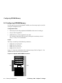
Preliminary
Compaq Computer Corporation
February 1999
The information in this publication is subject to change without notice.
COMPAQ COMPUTER CORPORATION SHALL NOT BE LIABLE FOR TECHNICAL OR EDITORIAL
ERRORS OR OMISSIONS CONTAINED HEREIN, NOR FOR INCIDENTAL OR CONSEQUENTIAL DAMAGES RESULTING FROM THE FURNISHING, PERFORMANCE, OR USE OF THIS MATERIAL. THIS
INFORMATION IS PROVIDED "AS IS" AND COMPAQ COMPUTER CORPORATION DISCLAIMS ANY
WARRANTIES, EXPRESS, IMPLIED OR STATUTORY AND EXPRESSLY DISCLAIMS THE IMPLIED WARRANTIES OF MERCHANTABILITY, FITNESS FOR PARTICULAR PURPOSE, GOOD TITLE AND AGAINST
INFRINGEMENT.
This publication contains information protected by copyright. No part of this publication may be photocopied or
reproduced in any form without prior written consent from Compaq Computer Corporation.
©1999 Digital Equipment Corporation.
All rights reserved. Printed in U.S.A.
COMPAQ, the Compaq logo, the Digital logo, and DIGITAL Registered in United States Patent and Trademark
Office.
AlphaPC, DECchip, DECnet, DIGITAL UNIX, OpenVMS, ThinWire, and Tru64 are trademarks of Compaq Computer Corporation.
Microsoft, MS-DOS, Windows, Windows NT, and Windows 95 are registered trademarks of Microsoft Corporation.
Other product names mentioned herein may be the trademarks of their respective owners.
17 February 1999 – Subject to Change
Contents
1
About This Manual
1.1
2
Power Requirements . . . . . . . . . . . . . . . . . . . . . . . . . . . . . . . . . . . . . . . . . . . . . .
Environmental Requirements . . . . . . . . . . . . . . . . . . . . . . . . . . . . . . . . . . . . . . . .
Physical Parameters . . . . . . . . . . . . . . . . . . . . . . . . . . . . . . . . . . . . . . . . . . . . . . .
AlphaPC 264DP Hole and Connector Specifications. . . . . . . . . . . . . . . . . . .
AlphaPC 264DP Daughtercard Mechanical Control Drawing . . . . . . . . . . . .
2-6
2-6
2-7
2-8
2-11
AlphaPC 264DP Switch Configuration
3.1
3.2
3.3
3.4
3.5
4
1-1
Features of the AlphaPC 264DP
2.1
2.2
2.3
2.3.1
2.3.2
3
Manual Conventions and Terminology . . . . . . . . . . . . . . . . . . . . . . . . . . . . . . . . .
Fail-Safe Booter . . . . . . . . . . . . . . . . . . . . . . . . . . . . . . . . . . . . . . . . . . . . . . . . . .
Mini-Debugger . . . . . . . . . . . . . . . . . . . . . . . . . . . . . . . . . . . . . . . . . . . . . . . . . . .
Password Bypass . . . . . . . . . . . . . . . . . . . . . . . . . . . . . . . . . . . . . . . . . . . . . . . . .
Flash Write Protection. . . . . . . . . . . . . . . . . . . . . . . . . . . . . . . . . . . . . . . . . . . . . .
21272 Speed. . . . . . . . . . . . . . . . . . . . . . . . . . . . . . . . . . . . . . . . . . . . . . . . . . . . .
3-3
3-3
3-3
3-3
3-4
AlphaPC 264DP Connector Pinouts
4.1
4.1.1
4.1.2
4.1.3
4.1.4
4.1.5
4.1.6
4.1.7
4.1.8
Mainboard Connectors . . . . . . . . . . . . . . . . . . . . . . . . . . . . . . . . . . . . . . . . . . . . .
Daughtercard Connector Pinouts . . . . . . . . . . . . . . . . . . . . . . . . . . . . . . . . .
PCI Bus Connector Pinouts . . . . . . . . . . . . . . . . . . . . . . . . . . . . . . . . . . . . . .
ISA Expansion Bus Connector Pinouts . . . . . . . . . . . . . . . . . . . . . . . . . . . . .
IDE Drive Bus Connector Pinouts . . . . . . . . . . . . . . . . . . . . . . . . . . . . . . . . .
Ultra SCSI Bus Connector Pinouts . . . . . . . . . . . . . . . . . . . . . . . . . . . . . . . .
SDRAM DIMM Connector Pinouts. . . . . . . . . . . . . . . . . . . . . . . . . . . . . . . . .
Diskette (Floppy) Drive Bus Connector Pinouts. . . . . . . . . . . . . . . . . . . . . . .
Parallel Bus Connector Pinouts . . . . . . . . . . . . . . . . . . . . . . . . . . . . . . . . . . .
17 February 1999 – Subject to Change
4-1
4-1
4-3
4-4
4-5
4-6
4-6
4-8
4-8
iii
4.1.9
4.1.10
4.1.11
4.1.12
4.1.13
4.1.14
4.1.15
4.1.16
4.1.17
4.1.18
4.1.19
4.2
4.2.1
4.2.2
4.2.3
4.2.4
5
5-1
5-2
Firmware Overview . . . . . . . . . . . . . . . . . . . . . . . . . . . . . . . . . . . . . . . . . . . . . . . .
Power-Up . . . . . . . . . . . . . . . . . . . . . . . . . . . . . . . . . . . . . . . . . . . . . . . . . . . .
Switching From One Firmware to the Other . . . . . . . . . . . . . . . . . . . . . . . . .
Preparing Diskettes. . . . . . . . . . . . . . . . . . . . . . . . . . . . . . . . . . . . . . . . . . . . . . . .
Fail-Safe Booter Utility . . . . . . . . . . . . . . . . . . . . . . . . . . . . . . . . . . . . . . . . . . . . .
Updating Firmware From AlphaBIOS . . . . . . . . . . . . . . . . . . . . . . . . . . . . . . . . . .
Updating Firmware From Alpha SRM Console with LFU . . . . . . . . . . . . . . . . . . .
Starting LFU. . . . . . . . . . . . . . . . . . . . . . . . . . . . . . . . . . . . . . . . . . . . . . . . . .
LFU Commands. . . . . . . . . . . . . . . . . . . . . . . . . . . . . . . . . . . . . . . . . . . . . . .
6-1
6-1
6-2
6-2
6-3
6-4
6-4
6-4
6-5
AlphaBIOS
7.1
7.2
7.2.1
7.2.2
7.2.3
7.2.4
7.2.5
iv
Memory Subsystem . . . . . . . . . . . . . . . . . . . . . . . . . . . . . . . . . . . . . . . . . . . . . . .
Configuring SDRAM Memory . . . . . . . . . . . . . . . . . . . . . . . . . . . . . . . . . . . . . . . .
Firmware Introduction
6.1
6.1.1
6.1.2
6.2
6.3
6.4
6.5
6.5.1
6.5.2
7
4-9
4-9
4-10
4-10
4-10
4-11
4-11
4-11
4-11
4-12
4-12
4-12
4-12
4-13
4-13
4-15
Memory Configuration
5.1
5.2
6
COM1/COM2 Serial Line Connector Pinouts. . . . . . . . . . . . . . . . . . . . . . . . .
Keyboard/Mouse Connector Pinouts . . . . . . . . . . . . . . . . . . . . . . . . . . . . . . .
+3-V Power Connector Pinouts . . . . . . . . . . . . . . . . . . . . . . . . . . . . . . . . . . .
+5-V Power Connector Pinouts . . . . . . . . . . . . . . . . . . . . . . . . . . . . . . . . . . .
Fan Box Power Connector Pinouts . . . . . . . . . . . . . . . . . . . . . . . . . . . . . . . .
Speaker Connector Pinouts . . . . . . . . . . . . . . . . . . . . . . . . . . . . . . . . . . . . . .
Halt Button Connector Pinouts . . . . . . . . . . . . . . . . . . . . . . . . . . . . . . . . . . .
Reset Button Connector Pinouts . . . . . . . . . . . . . . . . . . . . . . . . . . . . . . . . . .
System Power Button Connector Pinouts . . . . . . . . . . . . . . . . . . . . . . . . . . .
Ultra SCSI Hard Drive LED Connector Pinouts . . . . . . . . . . . . . . . . . . . . . . .
Power LED Connector Pinouts . . . . . . . . . . . . . . . . . . . . . . . . . . . . . . . . . . .
Daughtercard Connectors . . . . . . . . . . . . . . . . . . . . . . . . . . . . . . . . . . . . . . . . . . .
Microprocessor Fan Power Connector Pinouts . . . . . . . . . . . . . . . . . . . . . . .
SROM Test Data Input Connector Pinouts . . . . . . . . . . . . . . . . . . . . . . . . . .
AlphaPC 264DP Daughtercard Connector Pinouts . . . . . . . . . . . . . . . . . . . .
AlphaPC 264DP Daughtercard Input Power Connector Pinouts . . . . . . . . . .
AlphaBIOS Conventions . . . . . . . . . . . . . . . . . . . . . . . . . . . . . . . . . . . . . . . . . . . .
AlphaBIOS Setup Program . . . . . . . . . . . . . . . . . . . . . . . . . . . . . . . . . . . . . . . . . .
Displaying Your System Configuration . . . . . . . . . . . . . . . . . . . . . . . . . . . . .
Upgrading AlphaBIOS . . . . . . . . . . . . . . . . . . . . . . . . . . . . . . . . . . . . . . . . . .
Setting Up Your Hard Disk. . . . . . . . . . . . . . . . . . . . . . . . . . . . . . . . . . . . . . .
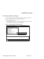
Performing CMOS Setup Tasks . . . . . . . . . . . . . . . . . . . . . . . . . . . . . . . . . .
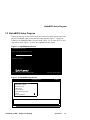
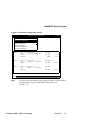
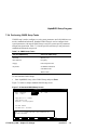
Running a Maintenance Program . . . . . . . . . . . . . . . . . . . . . . . . . . . . . . . . .
7-2
7-3
7-4
7-7
7-8
7-9
7-11
17 February 1999 – Subject to Change
7.3
7.3.1
7.3.2
7.3.3
8
7-13
7-13
7-14
7-14
Alpha SRM Console Firmware
8.1
8.2
8.3
8.3.1
8.3.2
8.3.3
8.3.4
8.3.5
8.3.6
8.4
8.4.1
8.5
8.6
8.6.1
8.6.2
8.6.3
8.6.4
8.7
8.8
8.9
8.10
8.11
8.12
8.13
8.13.1
9
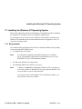
Installing the Windows NT Operating System. . . . . . . . . . . . . . . . . . . . . . . . . . . .
Requirements . . . . . . . . . . . . . . . . . . . . . . . . . . . . . . . . . . . . . . . . . . . . . . . .
Before Installing Windows NT . . . . . . . . . . . . . . . . . . . . . . . . . . . . . . . . . . . .
Starting Windows NT Setup. . . . . . . . . . . . . . . . . . . . . . . . . . . . . . . . . . . . . .
Alpha SRM Console Firmware Conventions. . . . . . . . . . . . . . . . . . . . . . . . . . . . .
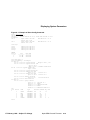
Basic Alpha SRM Console Command Descriptions . . . . . . . . . . . . . . . . . . . . . . .
Displaying System Parameters . . . . . . . . . . . . . . . . . . . . . . . . . . . . . . . . . . . . . . .
Displaying the System Configuration . . . . . . . . . . . . . . . . . . . . . . . . . . . . . . .
Displaying the Number of CPUs . . . . . . . . . . . . . . . . . . . . . . . . . . . . . . . . . .
Displaying System Devices . . . . . . . . . . . . . . . . . . . . . . . . . . . . . . . . . . . . . .
Displaying the Memory Configuration . . . . . . . . . . . . . . . . . . . . . . . . . . . . . .
Displaying PALcode Revision Information . . . . . . . . . . . . . . . . . . . . . . . . . . .
Displaying Console Revision Information . . . . . . . . . . . . . . . . . . . . . . . . . . .
Environment Variables . . . . . . . . . . . . . . . . . . . . . . . . . . . . . . . . . . . . . . . . . . . . .
Environment Variable Summary . . . . . . . . . . . . . . . . . . . . . . . . . . . . . . . . . .
Initializing the System . . . . . . . . . . . . . . . . . . . . . . . . . . . . . . . . . . . . . . . . . . . . . .
Making the System Secure . . . . . . . . . . . . . . . . . . . . . . . . . . . . . . . . . . . . . . . . . .
Set Password Command . . . . . . . . . . . . . . . . . . . . . . . . . . . . . . . . . . . . . . . .
Set Secure Command . . . . . . . . . . . . . . . . . . . . . . . . . . . . . . . . . . . . . . . . . .
Login Command . . . . . . . . . . . . . . . . . . . . . . . . . . . . . . . . . . . . . . . . . . . . . .
Clear Password Command . . . . . . . . . . . . . . . . . . . . . . . . . . . . . . . . . . . . . .
Examine and Deposit Commands. . . . . . . . . . . . . . . . . . . . . . . . . . . . . . . . . . . . .
Creating a Power-Up Script . . . . . . . . . . . . . . . . . . . . . . . . . . . . . . . . . . . . . . . . .
Starting and Stopping CPUs . . . . . . . . . . . . . . . . . . . . . . . . . . . . . . . . . . . . . . . . .
Getting Help . . . . . . . . . . . . . . . . . . . . . . . . . . . . . . . . . . . . . . . . . . . . . . . . . . . . .
Upgrading the System . . . . . . . . . . . . . . . . . . . . . . . . . . . . . . . . . . . . . . . . . . . . .
Booting the Operating System . . . . . . . . . . . . . . . . . . . . . . . . . . . . . . . . . . . . . . .
Installing the Tru64 UNIX Operating System . . . . . . . . . . . . . . . . . . . . . . . . . . . .
Requirements . . . . . . . . . . . . . . . . . . . . . . . . . . . . . . . . . . . . . . . . . . . . . . . .
8-1
8-3
8-18
8-18
8-20
8-20
8-21
8-22
8-22
8-22
8-24
8-28
8-28
8-29
8-30
8-31
8-32
8-33
8-35
8-36
8-37
8-38
8-40
8-44
8-44
Troubleshooting
9.1
9.2
9.3
9.4
9.5
9.6
9.7
Password Bypass . . . . . . . . . . . . . . . . . . . . . . . . . . . . . . . . . . . . . . . . . . . . . . . . .
Hardware Startup . . . . . . . . . . . . . . . . . . . . . . . . . . . . . . . . . . . . . . . . . . . . . . . . .
Daughtercard LEDs . . . . . . . . . . . . . . . . . . . . . . . . . . . . . . . . . . . . . . . . . . . . . . .
Beep Codes . . . . . . . . . . . . . . . . . . . . . . . . . . . . . . . . . . . . . . . . . . . . . . . . . . . . .
Post Codes . . . . . . . . . . . . . . . . . . . . . . . . . . . . . . . . . . . . . . . . . . . . . . . . . . . . . .
Fail-Safe Booter . . . . . . . . . . . . . . . . . . . . . . . . . . . . . . . . . . . . . . . . . . . . . . . . . .
Windows NT Startup . . . . . . . . . . . . . . . . . . . . . . . . . . . . . . . . . . . . . . . . . . . . . . .
17 February 1999 – Subject to Change
9-1
9-2
9-2
9-3
9-3
9-4
9-5
v
A
Support, Products, and Documentation
A.1
A.2
A.2.1
A.2.2
A.2.3
A.3
vi
Customer Support . . . . . . . . . . . . . . . . . . . . . . . . . . . . . . . . . . . . . . . . . . . . . . . . .
Supporting Products . . . . . . . . . . . . . . . . . . . . . . . . . . . . . . . . . . . . . . . . . . . . . . .
Memory . . . . . . . . . . . . . . . . . . . . . . . . . . . . . . . . . . . . . . . . . . . . . . . . . . . . .
Power Supply. . . . . . . . . . . . . . . . . . . . . . . . . . . . . . . . . . . . . . . . . . . . . . . . .
Enclosure . . . . . . . . . . . . . . . . . . . . . . . . . . . . . . . . . . . . . . . . . . . . . . . . . . . .
Associated Documentation . . . . . . . . . . . . . . . . . . . . . . . . . . . . . . . . . . . . . . . . . .
A-1
A-2
A-2
A-2
A-2
A-3
17 February 1999 – Subject to Change
Figures
2–1
2–2
2–3
2–4
2–5
2–6
3–1
3–2
3–3
5–1
5–2
6–1
7–1
7–2
7–3
7–4
7–5
7–6
7–7
7–8
7–9
7–10
7–11
8–1
8–2
8–3
8–4
8–5
8–6
8–7
8–8
8–9
8–10
8–11
8–12
8–13
8–14
8–15
8–16
8–17
8–18
8–19
8–20
AlphaPC 264DP Mainboard Switch/Connector/Component Location. . . . . . . . . .
AlphaPC 264DP Daughtercard Switch/Connector/Component Location . . . . . . .
AlphaPC 264DP Mainboard Hole Specifications . . . . . . . . . . . . . . . . . . . . . . . . .
AlphaPC 264DP Mainboard Connector Specifications . . . . . . . . . . . . . . . . . . . . .
AlphaPC 264DP Mainboard I/O Connector Specifications . . . . . . . . . . . . . . . . . .
AlphaPC 264DP Daughtercard Mechanical Control Drawing . . . . . . . . . . . . . . . .
Mainboard Switchpack 2 . . . . . . . . . . . . . . . . . . . . . . . . . . . . . . . . . . . . . . . . . . . .
Mainboard Switchpack 3 . . . . . . . . . . . . . . . . . . . . . . . . . . . . . . . . . . . . . . . . . . . .
Daughtercard Switchpack 2 . . . . . . . . . . . . . . . . . . . . . . . . . . . . . . . . . . . . . . . . .
AlphaPC 264DP Memory Subsystem . . . . . . . . . . . . . . . . . . . . . . . . . . . . . . . . . .
AlphaPC 264DP DIMM Connectors . . . . . . . . . . . . . . . . . . . . . . . . . . . . . . . . . . .
Example of Running LFU . . . . . . . . . . . . . . . . . . . . . . . . . . . . . . . . . . . . . . . . . . .
AlphaBIOS Boot Screen . . . . . . . . . . . . . . . . . . . . . . . . . . . . . . . . . . . . . . . . . . . .
AlphaBIOS Setup Screen . . . . . . . . . . . . . . . . . . . . . . . . . . . . . . . . . . . . . . . . . . .
Systemboard Configuration Screen . . . . . . . . . . . . . . . . . . . . . . . . . . . . . . . . . . .
Hard Disk Configuration Screen . . . . . . . . . . . . . . . . . . . . . . . . . . . . . . . . . . . . . .
Memory Configuration Screen . . . . . . . . . . . . . . . . . . . . . . . . . . . . . . . . . . . . . . .
Setup Screen Selecting AlphaBIOS Upgrade . . . . . . . . . . . . . . . . . . . . . . . . . . . .
Hard Disk Setup Screen . . . . . . . . . . . . . . . . . . . . . . . . . . . . . . . . . . . . . . . . . . . .
Standard CMOS Setup Screen . . . . . . . . . . . . . . . . . . . . . . . . . . . . . . . . . . . . . . .
Advanced CMOS Setup Screen . . . . . . . . . . . . . . . . . . . . . . . . . . . . . . . . . . . . . .
Run Maintenance Program Submenu. . . . . . . . . . . . . . . . . . . . . . . . . . . . . . . . . .
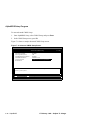
Entering the Program Name . . . . . . . . . . . . . . . . . . . . . . . . . . . . . . . . . . . . . . . . .
Example of Show Config Command . . . . . . . . . . . . . . . . . . . . . . . . . . . . . . . . . .
Example of Show CPU Command . . . . . . . . . . . . . . . . . . . . . . . . . . . . . . . . . . . .
Example of Show Device Command . . . . . . . . . . . . . . . . . . . . . . . . . . . . . . . . . .
Example of Show Memory Command . . . . . . . . . . . . . . . . . . . . . . . . . . . . . . . . .
Example of Show PAL Command . . . . . . . . . . . . . . . . . . . . . . . . . . . . . . . . . . . .
Example of Show Version Command . . . . . . . . . . . . . . . . . . . . . . . . . . . . . . . . .
Example of Set Envar and Show Envar Commands . . . . . . . . . . . . . . . . . . . . . .
Example of Initialize Command. . . . . . . . . . . . . . . . . . . . . . . . . . . . . . . . . . . . . . .
Examples of Set Password Command . . . . . . . . . . . . . . . . . . . . . . . . . . . . . . . . .
Examples of Set Secure Command . . . . . . . . . . . . . . . . . . . . . . . . . . . . . . . . . . .
Examples of Login Command . . . . . . . . . . . . . . . . . . . . . . . . . . . . . . . . . . . . . . .
Examples of Clear Password Command . . . . . . . . . . . . . . . . . . . . . . . . . . . . . . .
Examples of Deposit Command . . . . . . . . . . . . . . . . . . . . . . . . . . . . . . . . . . . . . .
Examples of Examine Command . . . . . . . . . . . . . . . . . . . . . . . . . . . . . . . . . . . . .
Example of Editing the nvram Script . . . . . . . . . . . . . . . . . . . . . . . . . . . . . . . . . .
Example of Clearing the nvram Script . . . . . . . . . . . . . . . . . . . . . . . . . . . . . . . . .
Example of Halt and Continue Commands . . . . . . . . . . . . . . . . . . . . . . . . . . . . .
Example of Help Command . . . . . . . . . . . . . . . . . . . . . . . . . . . . . . . . . . . . . . . . .
Example of Lfu Command . . . . . . . . . . . . . . . . . . . . . . . . . . . . . . . . . . . . . . . . . .
Example of Boot Command . . . . . . . . . . . . . . . . . . . . . . . . . . . . . . . . . . . . . . . . .
17 February 1999 – Subject to Change
2-3
2-5
2-8
2-9
2-10
2-11
3-1
3-2
3-2
5-1
5-2
6-4
7-3
7-3
7-4
7-5
7-6
7-7
7-8
7-9
7-10
7-11
7-12
8-19
8-20
8-21
8-21
8-22
8-22
8-23
8-28
8-29
8-30
8-31
8-32
8-34
8-34
8-36
8-36
8-37
8-38
8-39
8-41
vii
Tables
2–1
2–2
2–3
2–4
2–5
4–1
4–2
4–3
4–4
4–5
4–6
4–7
4–8
4–9
4–10
4–11
4–12
4–13
4–14
4–15
4–16
4–17
4–18
4–19
4–20
4–21
4–22
4–23
5–1
6–1
7–1
7–2
8–1
8–2
8–3
9–1
9–2
9–3
viii
AlphaPC 264DP Features . . . . . . . . . . . . . . . . . . . . . . . . . . . . . . . . . . . . . . . . . .
AlphaPC 264DP Mainboard Switch/Connector/Component List. . . . . . . . . . . . . .
AlphaPC 264DP Daughtercard Switch/Connector/Component List . . . . . . . . . . .
Power Supply DC Current Requirements . . . . . . . . . . . . . . . . . . . . . . . . . . . . . . .
AlphaPC 264DP Environmental Requirements. . . . . . . . . . . . . . . . . . . . . . . . . . .
Daughtercard Connector Pinouts (J18, J23) . . . . . . . . . . . . . . . . . . . . . . . . . . . .
PCI Bus Connector Pinouts (J35, J40–J42, J44, J46) . . . . . . . . . . . . . . . . . . . . .
ISA Expansion Bus Connector Pinouts (J47) . . . . . . . . . . . . . . . . . . . . . . . . . . . .
IDE Drive Bus Connector Pinouts (J45) . . . . . . . . . . . . . . . . . . . . . . . . . . . . . . . .
Ultra SCSI Bus Connector Pinouts (J34, J38) . . . . . . . . . . . . . . . . . . . . . . . . . . .
SDRAM DIMM Connector Pinouts (J1, J5, J6, J9, J11, J13, J14, J16, J25–J32).
Diskette (Floppy) Drive Bus Connector Pinouts (J43). . . . . . . . . . . . . . . . . . . . . .
Parallel Bus Connector Pinouts (J17) . . . . . . . . . . . . . . . . . . . . . . . . . . . . . . . . .
COM1/COM2 Serial Line Connector Pinouts (J19). . . . . . . . . . . . . . . . . . . . . . . .
Keyboard/Mouse Connector Pinouts (J21) . . . . . . . . . . . . . . . . . . . . . . . . . . . . . .
+3-V Power Connector Pinouts (J3) . . . . . . . . . . . . . . . . . . . . . . . . . . . . . . . . . . .
+5-V Power Connector Pinouts (J33) . . . . . . . . . . . . . . . . . . . . . . . . . . . . . . . . . .
Fan Box Power Connector Pinouts (J2, J15, J22, J24) . . . . . . . . . . . . . . . . . . . .
Speaker Connector Pinouts (J39) . . . . . . . . . . . . . . . . . . . . . . . . . . . . . . . . . . . . .
Halt Button Connector Pinouts (J12) . . . . . . . . . . . . . . . . . . . . . . . . . . . . . . . . . .
Reset Button Connector Pinouts (J8) . . . . . . . . . . . . . . . . . . . . . . . . . . . . . . . . . .
System Power Button Connector Pinouts (J7) . . . . . . . . . . . . . . . . . . . . . . . . . . .
Ultra SCSI Hard Drive LED Connector Pinouts (J10) . . . . . . . . . . . . . . . . . . . . . .
Power LED Connector Pinouts (J36) . . . . . . . . . . . . . . . . . . . . . . . . . . . . . . . . . .
Microprocessor Fan Power Connector Pinouts (J1) . . . . . . . . . . . . . . . . . . . . . . .
SROM Test Data Input Connector Pinouts (J2) . . . . . . . . . . . . . . . . . . . . . . . . . .
Daughtercard Connector Pinouts (J3) . . . . . . . . . . . . . . . . . . . . . . . . . . . . . . . . .
Input Power Connector Pinouts (J4) . . . . . . . . . . . . . . . . . . . . . . . . . . . . . . . . . . .
AlphaPC 264DP SDRAM Memory Configurations . . . . . . . . . . . . . . . . . . . . . . . .
LFU Commands . . . . . . . . . . . . . . . . . . . . . . . . . . . . . . . . . . . . . . . . . . . . . . . . . .
Action Keys . . . . . . . . . . . . . . . . . . . . . . . . . . . . . . . . . . . . . . . . . . . . . . . . . . . . . .
CMOS Setup Tasks . . . . . . . . . . . . . . . . . . . . . . . . . . . . . . . . . . . . . . . . . . . . . . .
Device Naming Convention . . . . . . . . . . . . . . . . . . . . . . . . . . . . . . . . . . . . . . . . .
Architecture-Required Environment Variables . . . . . . . . . . . . . . . . . . . . . . . . . . .
System-Defined Environment Variables . . . . . . . . . . . . . . . . . . . . . . . . . . . . . . .
AlphaPC 264DP Daughtercard LEDs . . . . . . . . . . . . . . . . . . . . . . . . . . . . . . . . . .
Beep Codes . . . . . . . . . . . . . . . . . . . . . . . . . . . . . . . . . . . . . . . . . . . . . . . . . . . . .
Post Codes . . . . . . . . . . . . . . . . . . . . . . . . . . . . . . . . . . . . . . . . . . . . . . . . . . . . .
2-1
2-4
2-5
2-6
2-7
4-1
4-3
4-4
4-5
4-6
4-6
4-8
4-8
4-9
4-9
4-10
4-10
4-10
4-11
4-11
4-11
4-11
4-12
4-12
4-12
4-13
4-13
4-15
5-3
6-5
7-2
7-9
8-20
8-24
8-25
9-2
9-3
9-3
17 February 1999 – Subject to Change
1
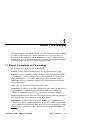
About This Manual
This manual describes the AlphaPC 264DP, a board for computing systems based on
the Alpha 21264 microprocessor and the companion 21272 core logic chipset. It
describes both the mainboard’s and the daughtercard’s features and how to set the
configuration switches. This manual helps users to install and populate the AlphaPC
264DP mainboard with memory boards and peripheral cards.
1.1 Manual Conventions and Terminology
The following conventions are used in this manual.
Caution: Cautions indicate potential damage to equipment, software, or data.
Extents: Extents are specified by a single number or a pair of numbers in brackets
([ ]) separated by a colon (:), and are inclusive. For example, bits [7:3] specify an
extent including bits 7, 6, 5, 4, and 3. Multiple bit fields are shown as extents.
Italic Type: Italic type emphasizes important information and indicates complete
titles of documents.
Note: Notes provide additional information about a topic.
Numbering: All numbers are decimal or hexadecimal unless otherwise indicated. In
case of ambiguity, a subscript indicates the radix of nondecimal numbers. For
example, 19 is a decimal number, but 1916 and 19A are hexadecimal numbers.
Register Figures: Register figures have bit and field position numbering starting at
the right (low-order) and increasing to the left (high-order).
Signal Names: All signal names are printed in boldface type. Signal names that
originate in an industry-standard specification, such as PCI or IDE, are printed in the
case as found in the specification (usually uppercase). Active low signals have either
a pound sign “#” appended, or a “not” overscore bar; for example, DEVSEL# and
RESET.
17 February 1999 – Subject To Change
About This Manual
1–1
Manual Conventions and Terminology
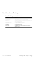
Terms: The following terms are used in this manual:
1–2
This term...
Refers to...
Microsoft Windows NT
installation guide
The Microsoft Windows NT Workstation Installation Guide
and the Windows NT Server Installation Guide
Windows NT
The Microsoft Windows NT Workstation and Windows NT
Server operating systems
Alpha SRM console
The Alpha SRM console firmware
AlphaBIOS
The AlphaBIOS firmware
Tru64 UNIX
COMPAQ’S 64-bit UNIX operating system, replacing
DIGITAL UNIX.
About This Manual
17 February 1999 – Subject To Change
2
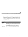
Features of the AlphaPC 264DP
The AlphaPC 264DP system (AlphaPC 264DP) consists of an AlphaPC 264DP
mainboard (a planar board, referred to as the mainboard throughout this document),
and one or two AlphaPC 264DP daughtercards (daughtercard). The daughtercard
consists of the 21264 microprocessor, L2 cache, reset FPGA, and power converters
for 2.2 volts and 1.5 volts.
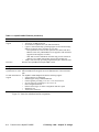
Table 2–1 provides an overview of the AlphaPC 264DP’s features.
Table 2–1 AlphaPC 264DP Features
Feature
Description
Mainboard
Daughtercards
Core logic chipset
Synchronous DRAM
(SDRAM) memory
Support for two daughtercards, each containing an Alpha 21264 microprocessor (64-bit RISC) operating at 500 MHz, and a 2MB, 128-bit L2 cache with
late-write HSTL synchronous static RAM (SSRAM).
21272 core logic chipset, comprising 11 chips (8 Dchips, 2 Pchips, and 1
Cchip) that provide an interface to system memory and the PCI bus.
128MB to 4GB memory complement, with 72-bit ECC — four memory
arrays, each consisting of four 200-pin buffered DIMMs, with qualified
100-MHz SDRAMs.
17 February 1999 – Subject To Change
Features of the AlphaPC 264DP
2–1
Table 2–1 AlphaPC 264DP Features (Continued)
Feature
Description
I/O and miscellaneous The AlphaPC 264DP mainboard has the following support:
support
• Two 64-bit, 33-MHz PCI buses
• Six 64-bit PCI expansion slots (one shared with ISA)
• Cypress CY82C693UB chip, providing support for PCI-to-ISA bridge,
IDE bus, keyboard, mouse, and time-of-year clock
– ISA expansion bus, with one ISA expansion slot (shared with PCI)
– IDE bus (Note: Only CD-ROM drives are supported. The maximum
supported cable length is 12 inches.)
– SMC FDC37C669 combination controller chip provides control for
diskettes, two UARTs with modem control, and a parallel port
• Adaptec AIC7895 chip, providing integrated dual-port, ultrawide SCSI
Firmware
Windows NT AlphaBIOS and Alpha SRM console.
Daughtercard
Microprocessor
Alpha 21264 microprocessor (64-bit RISC)
Synchronous L2 cache Onboard 2MB, direct-mapped, late-write SSRAM cache with 128-bit data
path
I/O and miscellaneous The AlphaPC 264DP daughtercard has the following support:
support
• 270-pin interface to mainboard
• SROM support using 512KB flash ROM
• Linear regulator, providing 3.3 V dc to 1.5 V dc conversion
• dc-to-dc converter, providing 5 V dc to 2.2 V dc
• Reset/configuration FPGA
• Presence detect logic, for cache configuration and CPU speed
• SROM test port
• 18-pin power connector
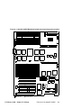
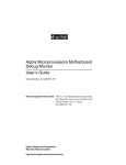
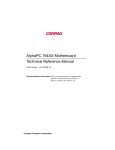
Figure 2–1 shows the mainboard and its components.
2–2
Features of the AlphaPC 264DP
17 February 1999 – Subject To Change
Figure 2–1 AlphaPC 264DP Mainboard Switch/Connector/Component Location
J1
J4
J5
J2
J6
J3
J7
J8
J10
J12
J9
J11
U1
J13
J14
J17
J16
J15
J18
J19
U8
U7
U6
U4
U5
U3
J20
U10
U9
U11
J21
U16
U13
U15
U12
U14
J22
J23
J25
J24
J26
D1
D2
J27
J28
J29
U26
J30
U28
U27
J31
J32
J34
J33
J35
J38
J36
J37
J39
J40
U31
U30
J41
XB1
U46
J42
SW2
B1
U49
U51
U50
J44
J43
SW3
J46
J45
U57
J47
indicates pin 1.
indicates switch 1.
17 February 1999 – Subject To Change
Features of the AlphaPC 264DP
2–3
Table 2–2 describes the mainboard components.
Table 2–2 AlphaPC 264DP Mainboard Switch/Connector/Component List
Item No.
Description
Item No.
Description
XB1
J1, J5, J6, J9,
J11, J13, J14,
J16, J25-J32
J2, J15, J22,
J24
J3
J4
J7
J8
RTC battery (CR2032)
Memory connectors
J45
J47
IDE bus connector
ISA bus connector
Fan box power connector
D1, D2
LEDs
+3-V power connector
Reserved
Power button connector
Reset button connector
Switchpacks
MIC29502
MC12439
DC4047 Dchips
J10
J12
J17
J18, J23
J19
J20
J21
J33
J34, J38
J35, J40-J42,
J44, J46
J36
J37
J39
J43
SCSI LED connector
Halt button connector
Parallel I/O connector
Daughtercard connectors
COM1/COM2 (DB9) connectors1
Reserved
Keyboard/mouse connector2
+5-V power connector
SCSI connectors
PCI bus connectors
SW2, SW3
U1
U3
U4, U5,
U7, U8,
U12, U13,
U15, U16
U6
U9, U10
U11
U14
U26
U27, U28
U30
U31
U46
U49
DC1046 Cchip
100LVE222
MC100LVEL37
MPC951
TIGbus FPGA
DC1048 Pchips
AlphaBIOS flash ROM
I2C bus controller
SRAM for SCSI
AIC7895
U50
U51
U57
SCSI BIOS flash ROM
Super I/O (FDC37C669)
Southbridge (CY82C693UB)
1
2
Power LED connector
Reserved
Speaker connector
Floppy drive connector
COM1 is the top connector, COM2 is the bottom one.
Mouse connector is on the top, keyboard connector is on the bottom.
2–4
Features of the AlphaPC 264DP
17 February 1999 – Subject To Change
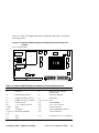
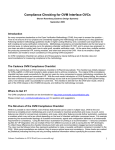
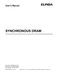
Figure 2–2 shows the daughtercard and its components, and Table 2–3 describes
these components.
Figure 2–2 AlphaPC 264DP Daughtercard Switch/Connector/Component
Location
Side 1–Component Side
U11
U7
J2
U6
J4
U4 U3
U15
U19
U10
U16
H2
H1
U2
U9
U18
U5
U1
U17
D5
D4
D3
D2
D1
SW2
indicates pin 1.
J1
U14
U13
U12
J3
indicates switch 1.
Table 2–3 AlphaPC 264DP Daughtercard Switch/Connector/Component List
Item No.
Description
Item No.
J1
Fan power
U5
J2
J3
J4
H1
H2
D1-D5
SW2
U1, U2, U9,
U10
U3
U4
SROM debug connector
Daughtercard data connector
Daughtercard power connector
21264 heat sink
+1.5-V regulator heat sink
LEDs
Switchpack
Bcache data SSRAMs
1489
1488
17 February 1999 – Subject To Change
Description
Microprocessor, socketed
(Alpha 21264)
U6
Bcache tag SSRAM
U7
Reset FPGA
U11, U13, U14 lcx38
U12
8582 EEPROM
U15
5-V to 2.2-V converter
U16
tl7702b supervisor
U17
512K×8 flash ROM, socketed
U18
74f151 multiplexer
U19
mic29302 3.3-V to 1.5-V regulator
Features of the AlphaPC 264DP
2–5
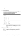
Power Requirements
2.1 Power Requirements
The mainboard has a maximum total power dissipation of 215 W, excluding any disk
drives. Each daughtercard has a maximum total power dissipation of 129 W.
Table 2–4 lists the current requirement for each dc supply voltage.
Table 2–4 Power Supply DC Current Requirements
Voltage/Tolerance
Current
Mainboard
+3.3 V dc, ±5%
30.0 A
+5 V dc, ±5%
20.0 A
5 VSB dc, ±5%
1.0 A
+12 V dc, ±5%
0.8 A
–12 V dc, ±5%
0.1 A
Daughtercard
+3.3 V dc, ±5%
5.0 A
+5 V dc, ±5%
22.0 A
+12 V dc, ±5%
0.1 A
–12 V dc, ±5%
0.05 A
Caution:
Fan sensor required. The 21264 microprocessor cooling fan must have
a built-in sensor that will drive a signal if the airflow stops. The sensor is
connected to power connector J1. When the signal is generated, it resets
the system.
2.2 Environmental Requirements
The 21264 microprocessor is cooled by a small fan blowing directly into the chip’s
heat sink. The daughtercard is designed to run efficiently by using only this fan.
Additional fans may be necessary depending upon cabinetry and the requirements of
plug-in cards.
2–6
Features of the AlphaPC 264DP
17 February 1999 – Subject To Change
Physical Parameters
The mainboard and daughtercard are specified to run within the environment listed
in Table 2–5.
Table 2–5 AlphaPC 264DP Environmental Requirements
Parameter
Specification
Operating temperature
10°C to 40°C (50°F to 104°F)
Storage temperature
–55°C to 125°C (–67°F to 257°F)
Relative humidity
10% to 90% with maximum wet bulb temperature
28°C (82°F) and minimum dew point 2°C (36°F)
Rate of (dry bulb) temperature change 11°C/hour ±2°C/hour (20°F/hour ±4°F/hour)
2.3 Physical Parameters
The AlphaPC 264DP mainboard is a printed-wiring board (PWB) with the following
dimensions:
•
Length: 42.11 cm (16.58 in ±0.0005 in)
•
Width: 33.02 cm (13.0 in ±0.0005 in)
•
Height: 3.81 cm (1.5 in)
The AlphaPC 264DP daughtercard is a PWB with the following dimensions:
•
Length: 30.48 cm (12.0 in ±0.0005 in)
•
Width: 14.99 cm (5.905 in ±0.0005 in)
•
Height: 6.40 cm (2.52 in ±0.0005 in)
17 February 1999 – Subject To Change
Features of the AlphaPC 264DP
2–7
Physical Parameters
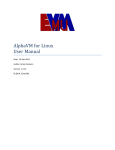
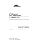
2.3.1 AlphaPC 264DP Hole and Connector Specifications
Figure 2–3 shows the mainboard’s hole specifications.
Figure 2–3 AlphaPC 264DP Mainboard Hole Specifications
180.98 mm (7.125 in.)
160.02 mm (6.300 in.)
0.00
2X 6.35 mm (.250 in.)
140.21 mm (5.520 in.)
12.83 mm (.505 in.)
4X 322.58 mm (12.700 in.)
325.12 mm (12.800 in.)
0.00
2X 5.08 mm (.200 in.)
15.27 mm (.601 in.)
16.26 mm (.640 in.)
76.33 mm (3.005 in.)
18X Æ 3.99 mm (.157 in.)
78.26 mm (3.081 in.)
2X 123.95 mm (4.880 in.)
128.78 mm (5.070 in.)
229.36 mm (9.030 in.)
228.09 mm (8.980 in.)
255.27 mm (10.050 in.)
2X 283.72 mm (11.170 in.)
317.50 mm (12.500 in.)
Æ 8.89 mm (.350 in.)
AREA TO BE FREE OF
COMP & ETCH EXCEPT
FOR CHASSIS 7 SYSTEM GROUND
387.29 mm (15.248 in.)
393.39 mm (15.488 in.)
397.63 mm (15.655 in.)
407.79 mm (16.055 in.)
2X 12.28 mm (.484 in.)
413.51 mm (16.280 in.)
2X 416.05 mm (16.380 in.)
3X 5.08 mm (.200 in.)
124.97 mm (4.920 in.)
7.87 mm (.310 in.)
215.90 mm (8.500 in.)
2–8
Features of the AlphaPC 264DP
324.99 mm (12.795 in.)
LK98-0001A
17 February 1999 – Subject To Change
Physical Parameters
Figure 2–4 shows the mainboard’s connector specifications.
Figure 2–4 AlphaPC 264DP Mainboard Connector Specifications
321.93 mm (12.675 in.)
148.59 mm (5.850 in.)
306.07 mm (12.050 in.)
0.00
2X 120.64 mm (4.750 in.)
6X 290.25 mm (11.427 in.)
ISA
103.53 mm (4.076 in.)
40.95 mm (1.612 in.)
330.20 mm (13.000 in.)
2.49 mm REF
(.098 in.)
0.00
9.66 mm (.380 in.)
12.22 mm (.481 in.)
30.29 mm (1.193 in.)
50.61 mm (1.993 in.)
70.93 mm (2.793 in.)
113.66 mm (4.475 in.)
91.25 mm (3.593 in.)
125.09 mm (4.925 in.)
111.57 mm (4.393 in.)
131.89 mm (5.193 in.)
141.42 mm (5.568 in.)
150.31 mm (5.918 in.)
159.20 mm (6.268 in.)
168.09 mm (6.618 in.)
2X 12.82 mm (.505 in.)
176.98 mm (6.968 in.)
185.87 mm (7.318 in.)
191.01 mm (7.520 in.)
194.76 mm (7.669 in.)
2X Ø 3.50 mm (.138 in.)
203.65 mm (8.018 in.)
NO COMP, NO ETCH
2X
217.48 mm (8.562 in.)
216.mm (8.542 in.)
223.58 mm (8.802 in.)
333.50 mm (13.130 in.)
349.70 mm (13.768 in.)
358.59 mm (14.118 in.)
358.39 mm (14.110 in.)
367.48 mm (14.468 in.)
376.37 mm (14.818 in.)
385.26 mm (15.168 in.)
360.68 mm (14.200 in.)
394.15 mm (15.518 in.)
403.04 mm (15.868 in.)
411.93 mm (16.218 in.)
412.87 mm (16.255 in.)
421.13 mm (16.580 in.)
4.69 mm
3X
(.185 in.)
3X
7.62 mm 7.62 mm
(.300 in.) (.300 in.)
2X 10.92 mm (.430 in.)
NO COMP,
NO ETCH
FAR SIDE
3X
2X 85.93 mm (3.383 in.)
140.97 mm (5.550 in.)
16X 172.08 mm (6.775 in.)
294.64 mm (11.600 in.)
2X 323.60 mm (12.740 in.)
312.55 mm (12.305 in.)
318.29 mm (12.531 in.)
319.53 mm (12.580 in.)
17 February 1999 – Subject To Change
LK98-0002A
Features of the AlphaPC 264DP
2–9
Physical Parameters
Figure 2–5 shows the top and side views of the mainboard’s I/O connectors.
Figure 2–5 AlphaPC 264DP Mainboard I/O Connector Specifications
Top View
Side View
13.97 mm (.550 in.)
MOUSE
2.97 mm (.117 in.)
261.74 mm (10.305 in.)
15.49 mm (.610 in.)
284.20 mm (11.189 in.)
158.08 mm
USB
(6.224 in.)
REF
312.62 mm (12.308 in.)
140.38 mm
DSUB STACKED 9M/9M
(5.527 in.)
REF
338.13 mm (13.312 in.)
114.05 mm
(4.490 in.)
DSUB 25
3.09 mm (.122 in.)
30.99 mm (1.220 in.)
2.27 mm (.089 in.)
59.69 mm (2.350 in.)
REF
66.44 mm
(2.616 in.)
REF
LK98-0003A
2–10
Features of the AlphaPC 264DP
17 February 1999 – Subject To Change
Physical Parameters
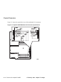
2.3.2 AlphaPC 264DP Daughtercard Mechanical Control Drawing
Figure 2–6 shows the mechanical control drawing for the AlphaPC 264DP daughtercard.
Figure 2–6 AlphaPC 264DP Daughtercard Mechanical Control Drawing
304.80 mm
(12.000 in.)
5.08 mm
(.2 in.)
3× φ 3.99 mm
(.157 in.)
2× 5.08 mm
(.2 in.)
135.5 mm
(5.335 in.)
149.99 mm
(5.905 in.)
5.08 mm
(.2 in.)
223.93 mm
(8.816 in.)
2× 5.08 mm
(.2 in.)
17 February 1999 – Subject To Change
Features of the AlphaPC 264DP
2–11
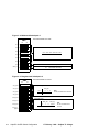
3
AlphaPC 264DP Switch Configuration
The AlphaPC 264DP mainboard has two sets of programmable switches, located at
SW2 and SW3, as shown in Figure 2–1. The AlphaPC 264DP daughtercard has one
switchpack, located at SW2, as shown in Figure 2–2. These switches set the
hardware configuration.
There are no switchpacks SW1 on production mainboards or daughtercards. Onboard resistors set the configuration (debug use on the mainboard; cache size, CPU speed, and flash ROM use on the daughtercard)
to the default state.
Note:
Figures 3–1 and 3–2 reflect the mainboard switches, and Figure 3–3 shows the
daughtercard switch configurations.
Figure 3–1 Mainboard Switchpack 2
Note: Switch defaults are in bold.
SW2
Off
fsb
1
coa
2
cob
3
mdb
4
sp0
5
sp1
6
sp2
7
pby
8
On
FSB:
Off
On
Reserved:
These switches must be kept at Off - Off.
Mini-Debugger:
Off
On
21272 Speed:
Normal boot
Fail-Safe Booter
Normal SROM flow
SROM jumps to Mini-Debugger
MHz
sp2
sp1
sp0
83.3
Off
On
On
Note: All other combinations are reserved.
This must be kept at 83.3 MHz.
AlphaBIOS Password Bypass:
Off
Normal operation
On
Bypass AlphaBIOS password
17 February 1999 – Subject To Change
AlphaPC 264DP Switch Configuration
3–1
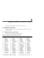
Figure 3–2 Mainboard Switchpack 3
Note: Switch defaults are in bold.
SW3
Off
cn7
1
cn6
2
cn5
3
cn4
4
cn3
5
cn2
6
spr
7
flash_wr
8
On
Reserved:
Note: The switches must remain as follows:
cn7
cn6
cn5
cn4
cn3
cn2
Off
Off
Off
On
Off
Off
Reserved:
This switch must be kept Off.
Flash Write Protect:
Off
On
Write enable flash ROM
Write disable flash ROM
Figure 3–3 Daughtercard Switchpack 2
Note: Switch defaults are in bold.
SW2
Off
vout_set0
1
vout_set1
2
vout_set2
3
On
Set Output Voltage:
vout_setx
V dc
2.214
vout_set3
4
flash_sel2
5
3
2
1
Note:
All other combinations are reserved.
0
On Off On On
Flash ROM Select:
flash_sel1
6
flash_sel0
7
flash_sel_
bypass
8
flash_selx
3–2
AlphaPC 264DP Switch Configuration
flash_sel_
2
1
0
bypass
Off
Off
Off
On
Note:
All other combinations are
reserved.
17 February 1999 – Subject To Change
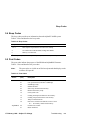
Fail-Safe Booter
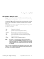
3.1 Fail-Safe Booter
The Fail-Safe Booter (FSB) utility provides an emergency recovery mechanism
when the primary firmware image contained in flash memory has been corrupted.
When flash memory has been corrupted, and no image can be loaded safely from the
flash ROM, you can run the FSB and boot another image from a diskette that is
capable of reprogramming the flash ROM. Refer to Chapter 6 for more information.
3.2 Mini-Debugger
The Alpha SROM Mini-Debugger is stored in the flash ROM and is enabled/
disabled by switch 4 of SW2 on the mainboard (see Figure 3–1). The default position
for this switch is off. When this switch is on, it causes the SROM initialization to trap
to the Mini-Debugger after all initialization is complete, but before starting the
execution of the system flash ROM code.
3.3 Password Bypass
AlphaBIOS provides password protection. However, if the use of passwords has
been enabled and you have forgotten the current password, password bypass is
provided through the use of switch 8 (pby) of SW2 on the mainboard.
Normal operation, with switch 8 in the off position (see Figure 3–1), requires a
password. The password bypass function is enabled by setting the switch to the on
position. This disables the AlphaBIOS password verification and enables the user to
set up or start up their system without the AlphaBIOS password. Password bypass
also clears the password.
After this function has been enabled, to disable it and require a password, set switch
8 to the off position.
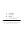
3.4 Flash Write Protection
The AlphaPC 264DP provides write protection for the firmware flash ROM. By
default, writing to the flash ROM is allowed, that is, switch 8 (flash_wr) of SW3 on
the mainboard is off (see Figure 3–2). To enable the flash write protection function,
set switch 8 to the on position.
Note:
The AlphaPC 264DP will not function if switch 8 is in the on position.
17 February 1999 – Subject To Change
AlphaPC 264DP Switch Configuration
3–3
21272 Speed
3.5 21272 Speed
The speed of the 21272 core logic chipset is determined by switches 5–7 of SW2 on
the mainboard. The default positions are 5 and 6 on, 7 off. These switches must be
kept in the default position.
3–4
AlphaPC 264DP Switch Configuration
17 February 1999 – Subject To Change
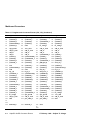
4
AlphaPC 264DP Connector Pinouts
This chapter lists the pinouts of the AlphaPC 264DP connectors.
4.1 Mainboard Connectors
Tables 4–1 through 4–19 show the mainboard connector pinouts. See Figure 2–1 for
connector locations.
4.1.1 Daughtercard Connector Pinouts
Table 4–1 shows the daughtercard connector pinouts.
Table 4–1 Daughtercard Connector Pinouts (J18, J23)
Pin
Signal
Pin
Signal
Pin
Signal
Pin Signal
1
5
9
13
17
21
25
29
33
37
41
45
49
53
57
61
vdd_3v
vdd_3v
sysdata2_l
syscheck0_l
sysdata14_l
sysdata17_l
sda
sysdata26_l
sysdata30_l
irq_2_h
tsu_speed1
sysaddin13_l
sysaddout13_l
sysaddout14_l
sysaddout6_l
sysaddout1_l
2
6
10
14
18
22
26
30
34
38
42
46
50
54
58
62
vdd_3v
vdd_3v
sysdata0_l
sysdata9_l
sysdataoutclk1_l
sysdata18_l
Gnd
sysdata25_l
syscheck3_l
irq_4_h
clk_rdy_h
sysaddin8_l
sysaddin7_l
sysaddout12_l
sysaddout0_l
sysdata60_l
3
7
11
15
19
23
27
31
35
39
43
47
51
55
59
63
vdd_3v
vdd_3v
sysdata5_l
sysdata10_l
sysdata16_l
sysdataoutclk2_l
Gnd
sysdatainclk3_l
clkfwdreset_h
2v_pwrgood_h
tsu_speed2
sysaddin9_l
sysaddin1_l
sysaddout10_l
sysaddout2_l
sysdatainclk7_l
4
8
12
16
20
24
28
32
36
40
44
48
52
56
60
64
17 February 1999 – Subject To Change
vdd_3v
vdd_3v
sysdata3_l
sysdata13_l
syscheck20_l
sysdata21_l
cpu_slot
sysdata28_l
irq_0_h
tsu_speed0
sysfillvalid_l
sysaddinclk_l
sysaddin3_l
sysaddoutclk_l
syscheck7_l
sysdata52_l
AlphaPC 264DP Connector Pinouts
4–1
Mainboard Connectors
Table 4–1 Daughtercard Connector Pinouts (J18, J23) (Continued)
Pin
Signal
65
69
73
77
81
85
89
93
97
101
105
109
113
117
121
125
129
133
137
141
145
149
153
157
161
165
169
173
177
181
to
211
215
4–2
Pin
Signal
Pin
Signal
Pin Signal
sysdata54_l
66 sysdata57_l
sysdata49_l
70 syscheck5_l
sysdata45_l
74 sysdata42_l
sysdataoutclk4_l 78 sysdata37_l
sysdata32_l
82 Gnd
cpu_speed1
86 +12v_mod
vdd_2v_term
90 vdd_2v_term
vdd_3v
94 vdd_3v
vdd_3v
98 vdd_3v
sysdata1_l
102 sysdataoutclk0_l
sysdata8_l
106 sysdatainclk1_l
sysdata15_l
110 sysdata19_l
sysdata22_l
114 sysdata23_l
sclk
118 syscheck2_l
sysdataoutclk3_l 122 sysdata29_l
Gnd
126 Gnd
irq_3_h
130 irq_5_h
sysaddin14_l
134 sysdatainvalid_l
sysaddin4_l
138 sysaddin5_l
sysaddout11_l
142 sysaddin0_l
sysaddout8_l
146 sysaddout5_l
sysdata63_l
150 sysdata62_l
sysdataoutclk7_l 154 sysdata53_l
sysdata56_l
158 sysdata58_l
sysdata48_l
162 sysdata44_l
sysdata40_l
166 sysdata38_l
sysdata34_l
170 sysdatainclk4_l
bc_config2
174 cpu_speed0
vdd_2v_term
178 vdd_2v_term
Gnd
212 pecl_clkin_h
67
71
75
79
83
87
91
95
99
103
107
111
115
119
123
127
131
135
139
143
147
151
155
159
163
167
171
175
179
213
sysdataoutclk6_l
sysdata46_l
sysdatainclk5_l
sysdata36_l
bc_config1
vdd_2v_term
vdd_3v
vdd_3v
sysdatainclk0_l
sysdata4_l
sysdata11_l
sysdatainclk2_l
pllbypass_h
sysdata24_l
sysdata31_l
fan_ok_l
mod_reset_l
sysaddin10_l
sysaddin2_l
sysaddout7_l
sysaddout4_l
sysdata61_l
syscheck6_l
sysdatainclk6_l
sysdataoutclk5_l
syscheck4_l
sysdata33_l
cpu_speed2
vdd_2v_term
pecl_clkin_l
68
72
76
80
84
88
92
96
100
104
108
112
116
120
124
128
132
136
140
144
148
152
156
160
164
168
172
176
180
214
frameclk_h
217 Gnd
to
270
216 frameclk_l
AlphaPC 264DP Connector Pinouts
sysdata51_l
sysdata47_l
sysdata41_l
sysdata35_l
bc_config3
vdd_2v_term
vdd_3v
vdd_3v
sysdata6_l
sysdata7_l
sysdata12_l
sysdata20_l
srom_en_l
sysdata27_l
sysdataoutvalid_l
irq_1_h
sysaddin11_l
sysaddin12_l
sysaddin6_l
sysaddout9_l
sysaddout3_l
sysdata59_l
sysdata55_l
sysdata50_l
sysdata43_l
sysdata39_l
bc_config0
−12v_mod
vdd_2v_term
Gnd
17 February 1999 – Subject To Change
Mainboard Connectors
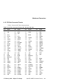
4.1.2 PCI Bus Connector Pinouts
Table 4–2 shows the PCI bus connector pinouts.
Table 4–2 PCI Bus Connector Pinouts (J35, J40–J42, J44, J46)
Pin
Signal
Pin
Signal
Pin
Signal
Pin
Signal
A1
A5
A9
A13
A17
A21
A25
A29
A33
A37
A41
A45
A49
A53
A57
A61
B3
B7
B11
B15
B19
B23
B27
B31
B35
B39
B43
B47
B51
B55
B59
TRST#
Vdd
—
Gnd
GNT#
+3V
AD[24]
AD[20]
+3V
STOP#
SBO#
+3V
AD[09]
+3V
AD[02]
Vdd
Gnd
INTB
PRSNT2#
Gnd
Vdd
AD[27]
AD[23]
+3V
IRDY#
LOCK#
+3V
AD[12]
Not used
AD[05]
Vdd
A2
A6
A10
A14
A18
A22
A26
A30
A34
A38
A42
A46
A50
A54
A58
A62
B4
B8
B12
B16
B20
B24
B28
B32
B36
B40
B44
B48
B52
B56
B60
+12V
INTA
Vdd
—
Gnd
AD[28]
IDSEL
Gnd
FRAME#
STOP#
Gnd
AD[13]
Not used
AD[06]
AD[00]
Vdd
TDO
INTD
Gnd
CLK
AD[31]
AD[25]
Gnd
AD[17]
+3V
PERR#
C/BE#[1]
AD[10]
AD[08]
AD[03]
ACK64#
A3
A7
A11
A15
A19
A23
A27
A31
A35
A39
A43
A47
A51
A55
A59
B1
B5
B9
B13
B17
B21
B25
B29
B33
B37
B41
B45
B49
B53
B57
B61
TMS
INTC
—
RST#
—
AD[26]
+3V
AD[18]
Gnd
+3V
PAR
AD[11]
Not used
AD[04]
Vdd
-12V
Vdd
PRSNT1#
Gnd
Gnd
AD[29]
+3V
AD[21]
C/BE#[2]
DEVSEL#
+3V
AD[14]
Gnd
AD[07]
Gnd
Vdd
A4
A8
A12
A16
A20
A24
A28
A32
A36
A40
A44
A48
A52
A56
A60
B2
B6
B10
B14
B18
B22
B26
B30
B34
B38
B42
B46
B50
B54
B58
B62
TDI
Vdd
Gnd
Vdd
AD[30]
Gnd
AD[22]
AD[16]
TRDY#
SDONE
AD[15]
Gnd
C/BE#[0]
Gnd
REQ64#
TCK
Vdd
—
—
REQ#
Gnd
C/BE#[3]
AD[19]
Gnd
Gnd
SERR#
Gnd
Not used
+3V
AD[01]
Vdd
17 February 1999 – Subject To Change
AlphaPC 264DP Connector Pinouts
4–3
Mainboard Connectors
Table 4–2 PCI Bus Connector Pinouts (J35, J40–J42, J44, J46) (Continued)
Pin
Signal
Pin
Signal
Pin
Signal
Pin
Signal
A63
A67
A71
A75
A79
A83
A87
A91
B63
B67
B71
B75
B79
B83
B87
B91
Gnd
PAR64
D[58]
Vdd
D[48]
D[42]
Gnd
D[32]
—
Gnd
D[59]
D[53]
Vdd
D[43]
D[37]
Gnd
A64
A68
A72
A76
A80
A84
A88
A92
B64
B68
B72
B76
B80
B84
B88
B92
C/BE#[7]
D[62]
Gnd
D[52]
D[46]
Vdd
D[36]
—
Gnd
D[63]
D[57]
Gnd
D[47]
D[41]
Vdd
—
A65
A69
A73
A77
A81
A85
A89
A93
B65
B69
B73
B77
B81
B85
B89
B93
C/BE#[5]
Gnd
D[56]
D[50]
Gnd
D[40]
D[34]
Gnd
C/BE#[6]
D[61]
Gnd
D[51]
D[45]
Gnd
D[35]
—
A66
A70
A74
A78
A82
A86
A90
A94
B66
B70
B74
B78
B82
B86
B90
B94
Vdd
D[60]
D[54]
Gnd
D[44]
D[38]
Gnd
—
C/BE#[4]
Vdd
D[55]
D[49]
Gnd
D[39]
D[33]
Gnd
4.1.3 ISA Expansion Bus Connector Pinouts
Table 4–3 shows the ISA expansion bus connector pinouts.
Table 4–3 ISA Expansion Bus Connector Pinouts (J47)
Pin
Signal
Pin
Signal
Pin
Signal
Pin
Signal
1
5
9
13
17
21
25
29
33
37
41
45
Gnd
Vdd
–5V
–12V
+12V
SMEMW#
IOW#
DACK3#
DACK1#
REFRESH#
IRQ7
IRQ5
2
6
10
14
18
22
26
30
34
38
42
46
IOCHCK#
SD6
SD4
SD2
SD0
AEN
SA18
SA16
SA14
SA12
SA10
SA8
3
7
11
15
19
23
27
31
35
39
43
47
RSTDRV
IRQ9
DRQ2
ZEROWS#
Gnd
SMEMR#
IOR#
DRQ3
DRQ1
SYSCLK
IRQ6
IRQ4
4
8
12
16
20
24
28
32
36
40
44
48
SD7
SD5
SD3
SD1
IOCHRDY
SA19
SA17
SA15
SA13
SA11
SA9
SA7
4–4
AlphaPC 264DP Connector Pinouts
17 February 1999 – Subject To Change
Mainboard Connectors
Table 4–3 ISA Expansion Bus Connector Pinouts (J47) (Continued)
Pin
Signal
Pin
Signal
Pin
Signal
Pin
Signal
49
53
57
61
65
69
73
77
81
85
89
93
97
IRQ3
TC
Vdd
Gnd
IOCS16#
IRQ11
IRQ15
DACK0#
DACK5#
DACK6#
DACK7#
Vdd
Gnd
50
54
58
62
66
70
74
78
82
86
90
94
98
SA6
SA4
SA2
SA0
LA23
LA21
LA19
LA17
MEMW#
SD9
SD11
SD13
SD15
51
55
59
63
67
71
75
79
83
87
91
95
—
DACK2#
BALE
OSC
MEMCS16#
IRQ10
IRQ12
IRQ14
DRQ0
DRQ5
DRQ6
DRQ7
MASTER#
—
52
56
60
64
68
72
76
80
84
88
92
96
—
SA5
SA3
SA1
SBHE#
LA22
LA20
LA18
MEMR#
SD8
SD10
SD12
SD14
—
4.1.4 IDE Drive Bus Connector Pinouts
Table 4–4 shows the IDE drive bus connector pinouts.
Table 4–4 IDE Drive Bus Connector Pinouts (J45)
Pin
Signal
Pin
Signal
Pin
Signal
Pin
Signal
1
5
9
13
17
21
25
29
33
37
DRST
IDE_D6
IDE_D4
IDE_D2
IDE_D0
IDE_REQ0
IOR#
MACK
ADDR1
CS0#
2
6
10
14
18
22
26
30
34
38
Gnd
IDE_D9
IDE_D11
IDE_D13
IDE_D15
Gnd
Gnd
Gnd
NC
CS1#
3
7
11
15
19
23
27
31
35
39
IDE_D7
IDE_D5
IDE_D3
IDE_D1
Gnd
IDE_IOW1#
CHRDY
IRQ
ADDR0
ACT#
4
8
12
16
20
24
28
32
36
40
IDE_D8
IDE_D10
IDE_D12
IDE_D14
NC (key pin)
Gnd
BALE
IOCS16#
ADDR2
Gnd
17 February 1999 – Subject To Change
AlphaPC 264DP Connector Pinouts
4–5
Mainboard Connectors
4.1.5 Ultra SCSI Bus Connector Pinouts
Table 4–5 shows the Ultra SCSI bus connector pinouts.
Table 4–5 Ultra SCSI Bus Connector Pinouts (J34, J38)
Pin
Signal
Pin
Signal
Pin
Signal
Pin
Signal
1
5
9
13
17
21
25
29
33
37
41
45
49
53
57
61
65
Gnd
Gnd
Gnd
Gnd
termpwr
Gnd
Gnd
Gnd
Gnd
scd14
scd1
scd5
Gnd
NC
bsy
sel
scd8
2
6
10
14
18
22
26
30
34
38
42
46
50
54
58
62
66
Gnd
Gnd
Gnd
Gnd
termpwr
Gnd
Gnd
Gnd
Gnd
scd15
scd2
scd6
Gnd
Gnd
ack
cd
scd9
3
7
11
15
19
23
27
31
35
39
43
47
51
55
59
63
67
Gnd
Gnd
Gnd
Gnd
NC
Gnd
Gnd
Gnd
scd12
scdph
scd3
scd7
termpwr
atn
reset
req
scd10
4
8
12
16
20
24
28
32
36
40
44
48
52
56
60
64
68
Gnd
Gnd
Gnd
Gnd
Gnd
Gnd
Gnd
Gnd
scd13
scd0
scd4
scdpl
termpwr
Gnd
msg
io
scd11
4.1.6 SDRAM DIMM Connector Pinouts
Table 4–6 shows the SDRAM DIMM connector pinouts.
Table 4–6 SDRAM DIMM Connector Pinouts (J1, J5, J6, J9, J11, J13, J14, J16, J25–J32)
Pin
Signal
Pin
Signal
Pin
Signal
Pin
Signal
1
5
9
13
17
21
25
Vdd
NC
dq67
dq64
NC
NC
NC
2
6
10
14
18
22
26
NC
NC
dq66
Vss
dq61
NC
Vdd
3
7
11
15
19
23
27
NC
NC
Vdd
dq63
dq60
Vss
dq51
4
8
12
16
20
24
28
NC
Vss
dq65
dq62
Vdd
NC
dq50
4–6
AlphaPC 264DP Connector Pinouts
17 February 1999 – Subject To Change
Mainboard Connectors
Table 4–6 SDRAM DIMM Connector Pinouts (J1, J5, J6, J9, J11, J13, J14, J16, J25–J32)
(Continued)
Pin
Signal
Pin
Signal
Pin
Signal
Pin
Signal
29
33
37
41
45
49
53
57
61
65
69
73
77
81
85
89
93
97
101
105
109
113
117
121
125
129
133
137
141
145
149
153
157
161
Vss
dq43
dq40
Vss
NC
NC
Vss
a0
dq34
Vss
dq25
dq18
Vss
dq15
dq12
Vss
NC
NC
NC
rfu
dq70
Vdd
dq59
dq56
Vss
dq47
dq44
Vss
a6
NC
Vss
NC
a10/ap
Vss
30
34
38
42
46
50
54
58
62
66
70
74
78
82
86
90
94
98
102
106
110
114
118
122
126
130
134
138
142
146
150
154
158
162
dq49
dq42
Vdd
a8
cke0
Vdd
cs2#
a1
Vdd
dq27
dq24
Vdd
NC
dq14
Vdd
dq5
NC
scl
NC
rfu
Vss
NC
dq58
Vdd
dq53
dq46
Vdd
dq37
a7
Vdd
NC
cs0#
Vdd
dq31
31
35
39
43
47
51
55
59
63
67
71
75
79
83
87
91
95
99
103
107
111
115
119
123
127
131
135
139
143
147
151
155
159
163
dq48
Vss
a4
a9
Vss
Vss
a11
Vss
dq33
dq26
Vss
dq17
NC
Vss
dq7
dq4
NC
NC
Vss
NC
dq69
Vss
Vss
dq55
dq52
Vss
dq39
dq36
Vss
dqm
clk0
Vss
a2
dq30
32
36
40
44
48
52
56
60
64
68
72
76
80
84
88
92
96
100
104
108
112
116
120
124
128
132
136
140
144
148
152
156
160
164
Vdd
dq41
a5
Vdd
cas#
ras#
Vdd
dq35
dq32
Vdd
dq19
dq16
Vdd
dq13
dq6
Vdd
NC
Vss
rege
dq71
dq68
NC
dq57
dq54
Vdd
dq45
dq38
Vdd
bs0
we#
Vdd
ba1
a3
Vdd
17 February 1999 – Subject To Change
AlphaPC 264DP Connector Pinouts
4–7
Mainboard Connectors
Table 4–6 SDRAM DIMM Connector Pinouts (J1, J5, J6, J9, J11, J13, J14, J16, J25–J32)
(Continued)
Pin
Signal
Pin
Signal
Pin
Signal
Pin
Signal
165
169
173
177
181
185
189
193
197
dq29
dq22
Vss
NC
NC
Vss
dq3
dq0
sa2
166
170
174
178
182
186
190
194
198
dq28
Vdd
NC
Vss
Vdd
dq9
dq2
sda
Vdd
167
171
175
179
183
187
191
195
199
Vss
dq21
NC
Vss
dq11
dq8
Vss
sa0
NC
168
172
176
180
184
188
192
196
200
dq23
dq20
Vdd
NC
dq10
Vdd
dq1
sa1
NC
4.1.7 Diskette (Floppy) Drive Bus Connector Pinouts
Table 4–7 shows the diskette (floppy) drive bus connector pinouts.
Table 4–7 Diskette (Floppy) Drive Bus Connector Pinouts (J43)
Pin
Signal
Pin
Signal
Pin
Signal
Pin
Signal
1
5
9
13
17
21
25
29
33
Gnd
Gnd
Gnd
Gnd
Gnd
Gnd
Gnd
Gnd
Gnd
2
6
10
14
18
22
26
30
34
DRVDEN0
DRVDEN1
MTR0
DS0
DIR
WDATA
TRK0
RDATA
DSKCHG
3
7
11
15
19
23
27
31
—
Gnd
Gnd
Gnd
Gnd
Gnd
Gnd
Gnd
Gnd
—
4
8
12
16
20
24
28
32
—
NC
INDEX
DS1
MTR1
STEP
WGATE
WRTPRT
HDSEL
—
4.1.8 Parallel Bus Connector Pinouts
Table 4–8 shows the parallel bus connector pinouts.
Table 4–8 Parallel Bus Connector Pinouts (J17)
Pin
Signal
Pin
Signal
Pin
Signal
Pin
Signal
1
5
9
PSTB
PD3
PD7
2
6
10
PD0
PD4
PACK
3
7
11
PD1
PD5
PBUSY
4
8
12
PD2
PD6
PE
4–8
AlphaPC 264DP Connector Pinouts
17 February 1999 – Subject To Change
Mainboard Connectors
Table 4–8 Parallel Bus Connector Pinouts (J17) (Continued)
Pin
Signal
Pin
Signal
Pin
Signal
Pin
Signal
13
17
21
25
PSLCT
PSLIN
Gnd
Gnd
14
18
22
—
PAFD
Gnd
Gnd
—
15
19
23
—
PAR_ERROR
Gnd
Gnd
—
16
20
24
—
PINIT
Gnd
Gnd
—
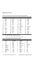
4.1.9 COM1/COM2 Serial Line Connector Pinouts
Table 4–9 shows the COM1/COM2 serial line connector pinouts.
Table 4–9 COM1/COM2 Serial Line Connector Pinouts (J19)
COM1 Pin
(Top)
COM1 Signal
COM2 Pin
(Bottom)
COM2 Signal
1
2
3
4
5
6
7
8
9
DCD1
SIN1
SOUT1
DTR1
Gnd
DSR1
RTS1
CTS1
RI1
10
11
12
13
14
15
16
17
18
DCD2
SIN2
SOUT2
DTR2
Gnd
DSR2
RTS2
CTS2
RI2
4.1.10 Keyboard/Mouse Connector Pinouts
Table 4–10 shows the keyboard/mouse connector pinouts.
Table 4–10 Keyboard/Mouse Connector Pinouts (J21)
Keyboard
Pin (Top)
Keyboard Signal
Mouse Pin
(Bottom)
Mouse Signal
1
2
3
4
5
6
KBDATA
NC
Gnd
Vdd
KBCLK
NC
7
8
9
10
11
12
17 February 1999 – Subject To Change
MSDATA
NC
Gnd
Vdd
MSCLK
NC
AlphaPC 264DP Connector Pinouts
4–9
Mainboard Connectors
4.1.11 +3-V Power Connector Pinouts
Table 4–11 shows the +3-V power connector pinouts.
Table 4–11 +3-V Power Connector Pinouts (J3)
Pin
Voltage
Pin
Voltage
Pin
Voltage
Pin
Voltage
1
5
9
13
17
21
vdd_3v
vdd_3v
vdd_3v
Gnd
Gnd
+12 V dc
2
6
10
14
18
22
Gnd
Gnd
Gnd
vdd_3v
vdd_3v
ps_on
3
7
11
15
19
23
vdd_3v
vdd_3v
vdd_3v
Gnd
Gnd
pok
4
8
12
16
20
24
Gnd
Gnd
Gnd
vdd_3v
vdd_3v
5vsb
4.1.12 +5-V Power Connector Pinouts
Table 4–12 shows the +5-V power connector pinouts.
Table 4–12 +5-V Power Connector Pinouts (J33)
Pin
Voltage
Pin
Voltage
Pin
Voltage
Pin
Voltage
1
5
9
13
vdd_5v
vdd_5v
Gnd
Gnd
2
6
10
14
Gnd
Gnd
vdd_5v
vdd_5v
3
7
11
15
vdd_5v
vdd_5v
Gnd
-12 V dc
4
8
12
16
Gnd
Gnd
vdd_5v
-5 V dc
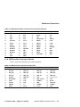
4.1.13 Fan Box Power Connector Pinouts
Table 4–13 shows the fan box power connector pinouts.
Table 4–13 Fan Box Power Connector Pinouts (J2, J15, J22, J24)
4–10
Pin
Voltage
Pin
Voltage
1
Gnd
2
+12 V dc
AlphaPC 264DP Connector Pinouts
17 February 1999 – Subject To Change
Mainboard Connectors
4.1.14 Speaker Connector Pinouts
Table 4–14 shows the speaker connector pinouts.
Table 4–14 Speaker Connector Pinouts (J39)
Pin
Signal
Description
1
2
3
4
spkr
vdd_5v
Gnd
vdd_5v
Speaker input
—
—
—
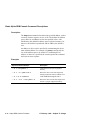
4.1.15 Halt Button Connector Pinouts
Table 4–15 shows the halt button connector pinouts.
Table 4–15 Halt Button Connector Pinouts (J12)
Pin
Signal
Description
1
2
halt_button
vdd_5v
Halt system (for Tru64 UNIX only)
—
4.1.16 Reset Button Connector Pinouts
Table 4–16 shows the reset button connector pinouts.
Table 4–16 Reset Button Connector Pinouts (J8)
Pin
Signal
Description
1
2
reset_button
vdd_5v
Reset system
—
4.1.17 System Power Button Connector Pinouts
Table 4–17 shows the system power button connector pinouts.
Table 4–17 System Power Button Connector Pinouts (J7)
Pin
Signal
Description
1
2
5vsb
Gnd
System power on/off
—
17 February 1999 – Subject To Change
AlphaPC 264DP Connector Pinouts
4–11
Daughtercard Connectors
4.1.18 Ultra SCSI Hard Drive LED Connector Pinouts
Table 4–18 shows the ultra SCSI hard drive LED connector pinouts.
Table 4–18 Ultra SCSI Hard Drive LED Connector Pinouts (J10)
Pin
Signal
Description
1
2
scsi_hd_act
vdd_5v
Hard drive active
—
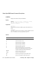
4.1.19 Power LED Connector Pinouts
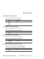
Table 4–19 shows the power LED connector pinouts.
Table 4–19 Power LED Connector Pinouts (J36)
Pin
Signal
Description
1
2
3
4
5
power_led
Gnd
NC
NC
NC
Power LED input
—
—
—
—
4.2 Daughtercard Connectors
Tables 4–20 through 4–23 show the daughtercard connector pinouts. See Figure 2–2
for connector locations.
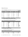
4.2.1 Microprocessor Fan Power Connector Pinouts
Table 4–20 shows the microprocessor fan power connector pinouts.
Table 4–20 Microprocessor Fan Power Connector Pinouts (J1)
4–12
Pin
Signal
Description
1,6
2,5
3,4
+12 V dc
Gnd
fan_conn_l
—
—
Fan connected
AlphaPC 264DP Connector Pinouts
17 February 1999 – Subject To Change
Daughtercard Connectors
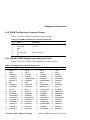
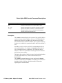
4.2.2 SROM Test Data Input Connector Pinouts
Table 4–21 shows the SROM test data input connector pinouts.
Table 4–21 SROM Test Data Input Connector Pinouts (J2)
Pin
Signal
Description
1
2
3
4
5
6
NC
srom_clk_l
Gnd
NC
test_srom_d_l
NC
—
Clock out
—
—
SROM serial data in
—
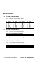
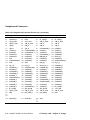
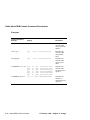
4.2.3 AlphaPC 264DP Daughtercard Connector Pinouts
Table 4–22 shows the AlphaPC 264DP daughtercard connector pinouts.
Table 4–22 Daughtercard Connector Pinouts (J3)
Pin
Signal
Pin
Signal
Pin
Signal
Pin Signal
1
5
9
13
17
21
25
29
33
37
41
45
49
53
57
61
65
69
73
vdd_3v
vdd_3v
sysdata2_l
syscheck0_l
sysdata14_l
sysdata17_l
sda
sysdata26_l
sysdata30_l
irq_2_h
tsu_speed1
sysaddin13_l
sysaddout13_l
sysaddout14_l
sysaddout6_l
sysaddout1_l
sysdata54_l
sysdata49_l
sysdata45_l
2
6
10
14
18
22
26
30
34
38
42
46
50
54
58
62
66
70
74
vdd_3v
vdd_3v
sysdata0_l
sysdata9_l
sysdataoutclk1_l
sysdata18_l
Gnd
sysdata25_l
syscheck3_l
irq_4_h
clk_rdy_h
sysaddin8_l
sysaddin7_l
sysaddout12_l
sysaddout0_l
sysdata60_l
sysdata57_l
syscheck5_l
sysdata42_l
3
7
11
15
19
23
27
31
35
39
43
47
51
55
59
63
67
71
75
vdd_3v
vdd_3v
sysdata5_l
sysdata10_l
sysdata16_l
sysdataoutclk2_l
Gnd
sysdatainclk3_l
clkfwdreset_h
2v_pwrgood_h
tsu_speed2
sysaddin9_l
sysaddin1_l
sysaddout10_l
sysaddout2_l
sysdatainclk7_l
sysdataoutclk6_l
sysdata46_l
sysdatainclk5_l
4
8
12
16
20
24
28
32
36
40
44
48
52
56
60
64
68
72
76
17 February 1999 – Subject To Change
vdd_3v
vdd_3v
sysdata3_l
sysdata13_l
syscheck20_l
sysdata21_l
cpu_slot
sysdata28_l
irq_0_h
tsu_speed0
sysfillvalid_l
sysaddinclk_l
sysaddin3_l
sysaddoutclk_l
syscheck7_l
sysdata52_l
sysdata51_l
sysdata47_l
sysdata41_l
AlphaPC 264DP Connector Pinouts
4–13
Daughtercard Connectors
Table 4–22 Daughtercard Connector Pinouts (J3) (Continued)
Pin
Signal
77
81
85
89
93
97
101
105
109
113
117
121
125
129
133
137
141
145
149
153
157
161
165
169
173
177
181
to
211
215
4–14
Pin
Signal
Pin
Signal
Pin Signal
sysdataoutclk4_l 78 sysdata37_l
sysdata32_l
82 Gnd
cpu_speed1
86 +12v_mod
vdd_2v_term
90 vdd_2v_term
vdd_3v
94 vdd_3v
vdd_3v
98 vdd_3v
sysdata1_l
102 sysdataoutclk0_l
sysdata8_l
106 sysdatainclk1_l
sysdata15_l
110 sysdata19_l
sysdata22_l
114 sysdata23_l
sclk
118 syscheck2_l
sysdataoutclk3_l 122 sysdata29_l
Gnd
126 Gnd
irq_3_h
130 irq_5_h
sysaddin14_l
134 sysdatainvalid_l
sysaddin4_l
138 sysaddin5_l
sysaddout11_l
142 sysaddin0_l
sysaddout8_l
146 sysaddout5_l
sysdata63_l
150 sysdata62_l
sysdataoutclk7_l 154 sysdata53_l
sysdata56_l
158 sysdata58_l
sysdata48_l
162 sysdata44_l
sysdata40_l
166 sysdata38_l
sysdata34_l
170 sysdatainclk4_l
bc_config2
174 cpu_speed0
vdd_2v_term
178 vdd_2v_term
Gnd
212 pecl_clkin_h
79
83
87
91
95
99
103
107
111
115
119
123
127
131
135
139
143
147
151
155
159
163
167
171
175
179
213
sysdata36_l
bc_config1
vdd_2v_term
vdd_3v
vdd_3v
sysdatainclk0_l
sysdata4_l
sysdata11_l
sysdatainclk2_l
pllbypass_h
sysdata24_l
sysdata31_l
fan_ok_l
mod_reset_l
sysaddin10_l
sysaddin2_l
sysaddout7_l
sysaddout4_l
sysdata61_l
syscheck6_l
sysdatainclk6_l
sysdataoutclk5_l
syscheck4_l
sysdata33_l
cpu_speed2
vdd_2v_term
pecl_clkin_l
80
84
88
92
96
100
104
108
112
116
120
124
128
132
136
140
144
148
152
156
160
164
168
172
176
180
214
frameclk_h
217 Gnd
to
270
216 frameclk_l
AlphaPC 264DP Connector Pinouts
sysdata35_l
bc_config3
vdd_2v_term
vdd_3v
vdd_3v
sysdata6_l
sysdata7_l
sysdata12_l
sysdata20_l
srom_en_l
sysdata27_l
sysdataoutvalid_l
irq_1_h
sysaddin11_l
sysaddin12_l
sysaddin6_l
sysaddout9_l
sysaddout3_l
sysdata59_l
sysdata55_l
sysdata50_l
sysdata43_l
sysdata39_l
bc_config0
−12v_mod
vdd_2v_term
Gnd
17 February 1999 – Subject To Change
Daughtercard Connectors
4.2.4 AlphaPC 264DP Daughtercard Input Power Connector Pinouts
Table 4–23 shows the input power connector pinouts.
Table 4–23 Input Power Connector Pinouts (J4)
Pin
Voltage
Pin Voltage
Pin Voltage
Pin Voltage
1
5
9
13
17
+5 V dc
+5 V dc
+5 V dc
+5 V dc
+5 V dc
2
6
10
14
18
3
7
11
15
4
8
12
16
Gnd
Gnd
Gnd
Gnd
Gnd
17 February 1999 – Subject To Change
+5 V dc
+5 V dc
+5 V dc
+5 V dc
Gnd
Gnd
Gnd
Gnd
AlphaPC 264DP Connector Pinouts
4–15
5
Memory Configuration
5.1 Memory Subsystem
The DRAM memory subsystem on the AlphaPC 264DP consists of sixteen 200-pin
buffered DIMM slots, which are organized as four arrays of memory. The 21272
chipset supports two 256-bit memory buses (288-bit including ECC) with two arrays
on each bus (see Figure 5–1).
The 72-bit, 100-MHz DIMMs consist of 64 bits of data and 8 bits of ECC, and can
be 32MB, 64MB, 128MB, or 256MB. The minimum configuration (one array populated with four 32MB DIMMs) is 128MB. The maximum configuration (four arrays
each populated with four 256MB DIMMs) is 4GB.
The memory cycle time is 83 MHz, identical to the 21272 chipset cycle time.
Note:
Although the memory cycle time is 83 MHz, qualified 100-MHz
DIMMs are required.
Figure 5–1 AlphaPC 264DP Memory Subsystem
21264
21272
Data Bus 1
Dchips
Data Bus 0
Pchips
Array 0 Array 2 Array 1 Array 3
Cchip
Address/Control
17 February 1999 – Subject To Change
Memory Configuration
5–1
Configuring SDRAM Memory
5.2 Configuring SDRAM Memory
For the memory system in the AlphaPC 264DP, one to four arrays may be used, following the configuration rules.
Configuration Rules
•
Each array must be fully populated with DIMMs of the same size and type.
•
Array 0 must be populated.
•
Additional arrays can be populated in any order.
For a memory subsystem with two arrays, placing the second array on bus 1
(array 1 or array 3) is recommended.
Arrays
The arrays are made up of the following connectors:
•
•
•
•
Array 0: J11, J14, J26, J28
Array 1: J1, J6, J30, J32
Array 2: J13, J16, J25, J27
Array 3: J5, J9, J29, J31
Figure 5–2 shows the relationship of the connectors/arrays. Refer to Figure 2–1 for
DIMM connector locations on the mainboard.
Figure 5–2 AlphaPC 264DP DIMM Connectors
(array 0)
(array 2)
(array 0)
(array 2)
(array 1)
(array 3)
(array 1)
(array 3)
Cchip
Bus 0
(array 2)
(array 0)
(array 2)
(array 0)
5–2
J1
J5
J6
J9
J11
J13
J14
J16
Memory Configuration
J25
J26
J27
J28
J29
J30
J31
J32
Bus 1
(array 3)
(array 1)
(array 3)
(array 1)
17 February 1999 – Subject To Change
Configuring SDRAM Memory
Possible Configurations
Memory sizes from 128MB to 4GB are supported.
Although not an exhaustive list, Table 5–1 lists some of the SDRAM memory
configurations available. Any combinations of DIMMs that meet the configuration
rules are supported by the 21272 chipset.
For a list of vendors who supply components and accessories for the
AlphaPC 264DP, see Appendix A.
Table 5–1 AlphaPC 264DP SDRAM Memory Configurations
Total Memory
Array 01
Array 11
Array 21
Array 31
128MB
256MB
32MB
32MB
64MB
128MB
64MB
128MB
64MB
256MB
128MB
64MB
256MB
128MB
256MB
256MB
256MB
256MB
256MB
—
32MB
—
—
64MB
64MB
64MB
—
128MB
64MB
128MB
128MB
256MB
256MB
256MB
256MB
256MB
—
—
—
—
—
—
64MB
—
—
64MB
—
64MB
—
128MB
128MB
256MB
256MB
—
—
—
—
—
—
—
—
—
64MB
—
64MB
—
—
128MB
128MB
256MB
512MB
768MB
1GB
1.5GB
2GB
2.5GB
3GB
3.5GB
4GB
1
Each array has 4 DIMMs.
17 February 1999 – Subject To Change
Memory Configuration
5–3
6
Firmware Introduction
This chapter introduces the operating system interfaces (firmware) that are stored in
the AlphaPC 264DP flash ROM:
•
AlphaBIOS
•
Alpha SRM console
It also describes two additional utilities that are used with the AlphaPC 264DP:
•
The Fail-Safe Booter (FSB) utility
•
The Loadable Firmware Update (LFU) utility
6.1 Firmware Overview
There are two interfaces that are included in the AlphaPC 264DP firmware, residing
in the flash ROM on the AlphaPC 264DP mainboard. They are defined as follows:
•
AlphaBIOS — The AlphaBIOS firmware initializes the system and allows you
to configure the system and install and boot the Windows NT operating system.
•
Alpha SRM console — The Alpha SRM console firmware initializes the system
and loads the AlphaBIOS firmware. It also allows you to configure the system
and install and boot the Tru64 UNIX operating system.
6.1.1 Power-Up
The Alpha SRM console is loaded at power-up to perform a few functions. The
Alpha SRM console then loads AlphaBIOS and passes control to it.
17 February 1999 – Subject To Change
Firmware Introduction
6–1
Preparing Diskettes
6.1.2 Switching From One Firmware to the Other
At times, you may find it necessary to switch from one firmware to the other. The
following sections describe the necessary steps.
From AlphaBIOS to Alpha SRM Console
To boot the Alpha SRM console while in AlphaBIOS, perform the following steps.
(For more information, refer to Chapter 7.)
1. At the AlphaBIOS boot screen, press F2 to reach the AlphaBIOS setup screen.
2. From the setup screen, use the Tab key to select CMOS Setup...
3. At the CMOS setup screen, press F6 to move to the Advanced CMOS setup
screen.
4. At the Advanced CMOS setup screen, use the Tab key to move to Console
Selection. Then use the down arrow key to toggle the console selection from
Windows NT Console (AlphaBIOS) to Tru64 UNIX (SRM Console).
5. Press F10 to save the changes and return to the CMOS setup screen.
6. Press F10 to save the changes and return to the AlphaBIOS setup screen.
7. Initialize the system by pressing the reset button or by power cycling the system.
From Alpha SRM Console to AlphaBIOS
To boot AlphaBIOS while in the Alpha SRM console, perform the following steps.
(For more information, refer to Chapter 8.)
1. At the Alpha SRM console prompt, enter the command set os_type nt.
2. Initialize the system by pressing the reset button or entering the init command.
6.2 Preparing Diskettes
The required firmware for your system is preloaded onto the flash ROM. Copies of
the firmware files may be included on your distribution CD, in case you need to
refresh the firmware. If they are not included, you can download them from the
Alpha OEM World Wide Web Internet site at http://www.digital.com/alphaoem.
Click on Technical Information, then click on Alpha Drivers and Firmware.
The utilities that are used to reload or update the firmware expect to find the files on
a diskette, so you need to prepare a diskette for each utility with the correct files from
the CD or the Web.
6–2
Firmware Introduction
17 February 1999 – Subject To Change
Fail-Safe Booter Utility
For FSB:
•
Copy the file PC264SRM.ROM onto a diskette, renaming it DP264SRM.ROM.
For Updating Firmware:
•
Copy the files PC264FW.TXT, PC264NT.ROM, and PC264SRM.ROM onto a
diskette.
For Installing Windows NT:
•
Copy the necessary files, as directed by installation instructions, onto a diskette
(see Section 7.3.1).
6.3 Fail-Safe Booter Utility
The FSB provides an emergency recovery mechanism when the firmware image
contained in flash memory has been corrupted. You can run the FSB and boot
another image from a diskette that is capable of reprogramming the flash ROM.
You can start the FSB in one of two ways:
•
If the firmware image is unavailable when the system is powered on or reset, the
FSB runs automatically. When the FSB runs, the system emits a series of beeps
through the speaker as beep code 1-2-3; that is, one beep and a pause, followed
by two beeps and a pause, followed by three beeps. After the diskette activity
light flashes, insert the diskette you created for the FSB. Then, reset the system
to restart the FSB. The FSB loads and runs the Alpha SRM console from this
diskette. Go to Section 6.5.1 and follow the procedures for updating your
firmware.
•
You can also start the FSB manually, as follows:
1. Power off your system.
2. Set switch 1 (FSB) of SW2 on the mainboard to on (see Figure 3–1).
3. Insert the FSB diskette you created into the diskette drive.
4. Power on your system, which brings up the Alpha SRM console.
5. Proceed to Section 6.5.1 and follow the procedures for updating your firmware.
17 February 1999 – Subject To Change
Firmware Introduction
6–3
Updating Firmware From AlphaBIOS
6.4 Updating Firmware From AlphaBIOS
At the the AlphaBIOS Setup screen, load the firmware update diskette you created,
then use the Tab key to select the AlphaBIOS Upgrade option and press Enter (see
Section 7.2.2). The AlphaBIOS automatically finds the firmware update files and
updates the appropriate firmware.
6.5 Updating Firmware From Alpha SRM Console with LFU
To update the firmware from the Alpha SRM console, start the Loadable Firmware
Update (LFU) utility, which then allows you to update the Alpha SRM console firmware, the AlphaBIOS firmware, and option firmware.
6.5.1 Starting LFU
At the Alpha SRM console prompt, issue the lfu command (see Section 8.11).
The LFU, upon being started, searches for the update firmware. You need to perform
the following steps to update the AlphaBIOS and the Alpha SRM console.
1. Load the diskette you created for the LFU.
2. Enter the device name dva0 when prompted for the location of the update files.
3. Enter the filename PC264FW.TXT when prompted. Note that the LFU has
already checked the contents of the diskette and should provide PC264FW.TXT
as the default.
PC264FW.TXT specifies which firmware is to be updated and passes the names of
the files that contain updated firmware. Figure 6–1 shows an example of running
LFU and updating firmware.
Figure 6–1 Example of Running LFU
P00>>>lfu
Checking dka400.4.0.7.1 for the option firmware files. . .
Checking dva0 for the option firmware files. . .
Option firmware files were not found on CD or floppy.
If you want to load the options firmware,
please enter the device on which the files are located(ewa0),
or just press <return> to proceed with a standard console update: dva0
Please enter the name of the options firmware files list, or
Press <return> to use the default filename (pc264fw.txt) : pc264fw.txt
Copying PC264FW.TXT from dva0. . .
Copying PC264NT.ROM from dva0. . .
Copying PC264SRM.ROM from dva0. . .
6–4
Firmware Introduction
17 February 1999 – Subject To Change
Updating Firmware From Alpha SRM Console with LFU
6.5.2 LFU Commands
Table 6–1 shows the commands available in the LFU.
Table 6–1 LFU Commands
Command
Description
display
Displays the system’s configuration table
exit
Exits LFU
list
Lists the device, revision, firmware name, and update revision
readme
Displays important release information
update
Replaces the current firmware with the loadable data image
verify
Compares the loadable and hardware images
? or help
Displays this command table
display
The display command shows the physical configuration of the system. Display is
equivalent to issuing the SRM console command show configuration. It shows you
the slot for each module, so display can help you identify the location of a device.
exit
The exit command terminates the LFU program, causes system initialization and
testing, and returns the system to the console from which LFU was called.
help
The help (or ?) command displays the LFU command list, shown below.
Function
Description
Display
Displays the system’s configuration table.
Exit
Done exit LFU (reset).
List
Lists the device, revision, firmware name, and update revision.
Readme
Lists important release information
Update
Replaces current firmware with loadable data image.
Verify
Compares loadable and hardware image.
? or Help
Scrolls this function table.
17 February 1999 – Subject To Change
Firmware Introduction
6–5
Updating Firmware From Alpha SRM Console with LFU
list
The list command displays the inventory of update firmware on the CD-ROM,
floppy, or network. Only the devices listed at your terminal are supported for firmware updates.
The list command shows three pieces of information for each device:
•
Current Revision – The revision of the device’s current firmware
•
Filename – The name of the file used to update that firmware
•
Update Revision – The revision of the firmware update image
readme
The readme command lists release notes for the LFU program.
update
The update command writes new firmware to the module. Then LFU automatically
verifies the update by reading the new firmware image from the module into memory and comparing it with the source image.
To update more than one device, you may use a wildcard but not a list. For example,
update k* updates all devices with names beginning with k, and update * updates all
devices.
When you do not specify a device name, LFU tries to update all devices; it lists the
selected devices to update and prompts before devices are updated. The default is no.
The -all option eliminates the update confirmation requests, enabling the update to
proceed without operator intervention.
Caution:
Never abort an update operation. Aborting corrupts the firmware on the
module.
verify
The verify command reads the firmware from the module into memory and compares it with the update firmware. If a module was verified when it was updated, but
later failed tests, use verify to determine whether the firmware has become corrupted.
6–6
Firmware Introduction
17 February 1999 – Subject To Change
7
AlphaBIOS
The AlphaBIOS firmware initializes the system and enables you to install and boot
the Windows NT operating system. This firmware resides in the flash ROM on the
AlphaPC 264DP mainboard. The mainboard ships with AlphaBIOS firmware and
online documentation that describes how to configure the firmware for Windows NT.
This chapter contains a subset of the AlphaBIOS help file on the distribution
medium. You can access the complete documentation online when your system is up
and running, or from another Windows system.
The online documentation describes configuration information for Alpha systems
running AlphaBIOS. The online documentation resides on the distribution medium.
The documentation is available as a Windows Help file compatible with Windows
NT 4.0 and Windows 95.
17 February 1999 – Subject To Change
AlphaBIOS
7–1
AlphaBIOS Conventions
7.1 AlphaBIOS Conventions
AlphaBIOS uses universally accepted keys and key combinations for navigating the
interface and selecting items. If you are familiar with MS-DOS or Microsoft
Windows keyboard conventions, navigating AlphaBIOS is simple. Table 7–1 shows
the keys to use for navigating and selecting items in AlphaBIOS.
Table 7–1 Action Keys
Press...
To...
TAB
Move highlight forward between fields of a dialog
SHIFT + TAB
Move highlight backwards between fields of a dialog
↑ or ↓
Move highlight within a menu, or cycle through available field values in a dialog window
ALT + ↓
Drop down a menu of choices from a drop-down listbox. A dropdown listbox can be recognized by the symbol ⇓
HOME
Move to the beginning of a text entry field
END
Move to the end of a text entry field
← →
Move to the left or right in a text entry field
ESC
Discard changes and back up to previous screen
Two levels of keyboard help are available:
7–2
•
Press F1 once to display explanations of the keystrokes available for the currently displayed part of AlphaBIOS.
•
Press F1 twice to display explanations of the keystrokes available for navigating
throughout AlphaBIOS.
AlphaBIOS
17 February 1999 – Subject To Change
AlphaBIOS Setup Program
7.2 AlphaBIOS Setup Program
When you power up or reset your system, the boot screen with the system logo is displayed. Pressing F2 at this screen starts the setup program. Figure 7–1 shows an
example of an AlphaBIOS Boot Screen with the “Press <F2> to enter SETUP” message at the bottom. Figure 7–2 shows the AlphaBIOS Setup Screen.
Figure 7–1 AlphaBIOS Boot Screen
AlphaBIOS Version 5.68
Please select the operating system to start:
Windows NT Server 4.00
Press Enter to choose.
digi tal
Press <F8> for NT5 advanced startup options.
Press <F2> to enter SETUP
Figure 7–2 AlphaBIOS Setup Screen
AlphaBIOS Setup
F1=Help
Display System Configuration...
AlphaBIOS Upgrade...
Hard Disk Setup...
CMOS Setup...
Network Setup...
Install Operating System
Utilities
About AlphaBIOS
Press ENTER to display the system configuration.
ESC=Exit
17 February 1999 – Subject To Change
AlphaBIOS
7–3
AlphaBIOS Setup Program
7.2.1 Displaying Your System Configuration
You can use AlphaBIOS to display your system configuration in a clear, easy-to-read
format, organized by categories: system board, memory, hard disk, PCI, SCSI, and
peripherals.
To display your system configuration:
1. Start AlphaBIOS Setup, select Display System Configuration, and press Enter.
2. In the Display System Configuration screen, use the arrow keys to select the
configuration category that you want to see, such as the examples shown in
Figures 7–3 through 7–5.
Figure 7–3 Systemboard Configuration Screen
Display System Configuration
F1=Help
Systemboard Configuration
Hard Disk Configuration
PCI Configuration
SCSI Configuration
ISA Configuration
Memory Configuration
Integrated Peripherals
System Type:
Processor:
Speed:
Cache:
Memory:
AlphaPC 264DP
Digital Alpha 21264, Revision 2.3
500 MHz
2 MB
512 MB
(2 Processors)
Floppy Drive A: 3.5" 1.44 MB
Floppy Drive B: None
Keyboard: U.S. 101-keyboard
AlphaBIOS Version:
5.68
981014.1813
ESC=Exit
7–4
AlphaBIOS
17 February 1999 – Subject To Change
AlphaBIOS Setup Program
Figure 7–4 Hard Disk Configuration Screen
Display System Configuration
F1=Help
Systemboard Configuration
Hard Disk Configuration
PCI Configuration
SCSI Configuration
ISA Configuration
Memory Configuration
Integrated Peripherals
Disk
Disk
Disk
0
1
2
AIC78XX
DEC
Partition 1
Partition 2
#0, SCSI ID 0
RZ1CB−CS (C) DEC0656
AIC78XX
DEC
Partition 1
#0, SCSI ID 1
RZ1CB−CS (C) DEC0656
AIC78XX
DEC
Partition 1
#0, SCSI ID 2
RZ29B
(C) DEC0656
4091 MB
4085 MB
6 MB
FAT
FAT
4091 MB
4091 MB
NTFS
4091 MB
4091 MB
NTFS
ESC=Exit
Note:
This screen is for information only; it cannot be edited. To make changes
to the hard-disk setup, use the Hard Disk Setup screen (see
Section 7.2.3).
17 February 1999 – Subject To Change
AlphaBIOS
7–5
AlphaBIOS Setup Program
Figure 7–5 Memory Configuration Screen
Display System Configuration
F1=Help
Systemboard Configuration
Hard Disk Configuration
PCI Configuration
SCSI Configuration
ISA Configuration
Memory Configuration
Integrated Peripherals
System Memory Configuration
Array 0: 256 MB (64 MB per DIMM)
— Starting Address =
0x00000000
Array 1: 256 MB (64 MB per DIMM)
— Starting Address =
0x10000000
Array 2: 256 MB (64 MB per DIMM)
— Starting Address =
0x20000000
Array 3: 256 MB (64 MB per DIMM)
— Starting Address =
0x30000000
ESC=Exit
7–6
AlphaBIOS
17 February 1999 – Subject To Change
AlphaBIOS Setup Program
7.2.2 Upgrading AlphaBIOS
As new versions of Windows NT are released, it might be necessary to upgrade
AlphaBIOS to the latest version. Also, as improvements are made to AlphaBIOS,
you may wish to upgrade to take advantage of new features.
To upgrade from an earlier version of AlphaBIOS:
1. Insert the diskette or CD-ROM containing the AlphaBIOS upgrade.
2. If you are not already running AlphaBIOS Setup, restart your system and press
F2 when the boot screen is displayed.
3. In the main AlphaBIOS Setup screen, use the Tab key to select AlphaBIOS
Upgrade and press Enter (see Figure 7–6). Then follow the instructions on the
AlphaBIOS Upgrade screen.
Figure 7–6 Setup Screen Selecting AlphaBIOS Upgrade
AlphaBIOS Setup
F1=Help
Display System Configuration...
AlphaBIOS Upgrade...
Hard Disk Setup...
CMOS Setup...
Network Setup...
Install Operating System
Utilities
About AlphaBIOS
Press ENTER to install new firmware image(s) from floppy, CD-ROM, or
network.
ESC=Exit
17 February 1999 – Subject To Change
AlphaBIOS
7–7
AlphaBIOS Setup Program
7.2.3 Setting Up Your Hard Disk
Express hard-disk setup is an easy way to create the recommended partition arrangement on your first hard disk, disk 0. Note, however, that express hard-disk setup does
not format the large partition with NTFS. You will have the opportunity to do this
during the Windows NT installation. Figure 7–7 shows an example of the Hard Disk
Setup screen.
Note:
AlphaBIOS assigns “disk 0” to the hard disk with the lowest SCSI ID
number on the first bus in your system.
Caution:
If you have any information on your disk that you want to save, be sure
to back it up before using express hard-disk setup.
Figure 7–7 Hard Disk Setup Screen
Hard Disk Setup
Disk
Disk
Disk
0
1
2
AIC78XX
Partition 1
Partition 2
#0, SCSI ID 0
AIC78XX
Partition 1
#0, SCSI ID 1
AIC78XX
Partition 1
#0, SCSI ID 2
F1=Help
4091 MB
4085 MB
6 MB
FAT
FAT
4091 MB
4091 MB
NTFS
4091 MB
4091 MB
NTFS
INSERT=New DEL=Delete F6=Format F7=Express ESC=Exit
To perform express hard-disk setup:
1. If you have any needed information on your disk, back it up before proceeding.
2. Start AlphaBIOS Setup, select Hard Disk Setup, and press Enter.
3. Press F7 to enter express hard-disk setup.
4. Press F10 to continue with the setup.
For information on manually managing hard disks, see the online documentation.
7–8
AlphaBIOS
17 February 1999 – Subject To Change
AlphaBIOS Setup Program
7.2.4 Performing CMOS Setup Tasks
CMOS Setup is used to configure several system parameters and is divided into two
modes, standard and advanced. Standard CMOS Setup is used to configure basic
system parameters; Advanced CMOS Setup is used for system-specific parameters
and password protection. Table 7–2 lists the specific tasks that you can perform in
standard and advanced setup mode.
Table 7–2 CMOS Setup Tasks
Standard CMOS Setup
Advanced CMOS Setup
Autostart
Memory test
Date and time
PCI parity
Floppy
Password protection
Keyboard
SCSI BIOS emulation
S/G DMA mode
Warm reboot
To enter standard CMOS Setup:
•
Start AlphaBIOS Setup, select CMOS Setup, and press Enter.
Figure 7–8 shows a sample standard CMOS Setup screen.
Figure 7–8 Standard CMOS Setup Screen
CMOS Setup
Date:
Time:
Wednesday,
13:22:27
August
19,
F1=Help
1998
Floppy Drive A: 3.5” 1.44 MB
Floppy Drive B: None
Keyboard: U.S. 101-key keyboard
Auto Start: Enabled
Auto Start Count: 30 Seconds
Press ↑ or ↓ to modify date fields. Date modifications will
take effect immediately.
F3=Color F6=Advanced F7=Default ESC=Discard Changes F10=Save Changes
17 February 1999 – Subject To Change
AlphaBIOS
7–9
AlphaBIOS Setup Program
To enter advanced CMOS Setup:
1. Start AlphaBIOS Setup, select CMOS Setup, and press Enter.
2. In the CMOS Setup screen, press F6.
Figure 7–9 shows a sample advanced CMOS Setup screen.
Figure 7–9 Advanced CMOS Setup Screen
CMOS Setup
F1=Help
Advanced CMOS Setup
PCI Parity Checking:
Power-up Memory Test:
AlphaBIOS Password Option:
SCSI BIOS Emulation:
Console Selection:
Warm Reboot
F1=Help
Disabled
Full
Disabled
Enabled for All
xxxxxxxxxxx
Windows NT Console (AlphaBIOS)
Disabled
Press ↑ or ↓ to select the firmware console that will be presented the next time the
system is power-cycled.
ESC=Discard Changes F10=Save Changes
7–10
AlphaBIOS
17 February 1999 – Subject To Change
AlphaBIOS Setup Program
7.2.5 Running a Maintenance Program
You can run maintenance programs such as the RAID configuration utility (RCU)
and other utilities directly from the AlphaBIOS utility menu.
To run a maintenance program:
1. Start AlphaBIOS Setup, select Utilities, select Run Maintenance Program from
the submenu shown in Figure 7–10, and press Enter.
Figure 7–10 Run Maintenance Program Submenu
AlphaBIOS Setup
Display System Configuration...
AlphaBIOS Upgrade...
Hard Disk Setup...
CMOS Setup...
Network Setup...
Install Operating System
Utilities
About AlphaBIOS
F1=Help
OS Selection Setup...
Run Maintenance Program...
Press ENTER to run an AlphaBIOS maintenance program.
ESC=Exit
17 February 1999 – Subject To Change
AlphaBIOS
7–11
AlphaBIOS Setup Program
2. In the Run Maintenance Program dialog box, type the name of the program to be
run at the Program Name prompt, as shown in Figure 7–11. Then tab to the
Location listbox and select the hard-disk partition, floppy diskette, or CD-ROM
drive from which to run the program.
3.
Press Enter to execute the program.
Figure 7–11 Entering the Program Name
AlphaBIOS Setup
Display System Configuration...
AlphaBIOS Upgrade...
Hard Disk Setup...
Run Maintenance Program
F1=Help
CMOS Setup...
Network Setup...
Program Name: swxcrmgr.exe
Run ECU floppy...
Install Setup...
OS Selection Setup...
Utilities
Run Maintenance Program...
About AlphaBIOS Location: :
ENTER=Execute
A:
CD:
Disk 0, Partition 1
Disk 0, Partition 2
Disk 1, Partition 1
If you are running a utility from a floppy diskette, you can simply type the utility’s
name into the Program Name field, and press Enter. This is because the floppy drive
is the default selection in the Current Partition field.
Use Alt + ↓ when a listbox is selected to open the list.
7–12
AlphaBIOS
17 February 1999 – Subject To Change
Installing the Windows NT Operating System
7.3 Installing the Windows NT Operating System
This section supplements the Microsoft Windows NT installation guide for installing
the Windows NT operating system on an AlphaPC 264DP system.
If you already have a previous version of Windows NT installed, see the Microsoft
Windows NT installation guide for information about how to upgrade to a new version of the operating system.
7.3.1 Requirements
You need the following hardware and software to install the Windows NT operating
system on an AlphaPC 264DP system:
•
A 100MB or larger SCSI drive
Note:
For information regarding supported SCSI hard drives, CD-ROM
drives, and controllers supported as boot/installation devices, see the
README.TXT file on the distribution medium.
•
The Microsoft Windows NT compact disk
•
The Installing Windows NT diskette you created
Note:
A diskette is required for installing the Windows NT 4.0 operating system. Future versions of Windows NT may not require this diskette. Contact your OEM or system vendor for details.
If your system came with a Windows NT 4.0 installation diskette, you
do not need to create a new diskette.
17 February 1999 – Subject To Change
AlphaBIOS
7–13
Installing the Windows NT Operating System
7.3.2 Before Installing Windows NT
Before installing Windows NT, ensure that you have completed the following tasks:
•
Use the CMOS Setup program to:
–
Set the system date and time
–
Verify that all other standard CMOS settings match your system.
Refer to Section 7.2.4 for more information about the CMOS Setup program.
•
Perform an express hard-disk setup. This configures the first hard disk that
AlphaBIOS detects in your system with the recommended default partition
arrangement. See Section 7.2.3 for more information on setting up your hard
disk. If you do not want to use the express hard-disk setup, refer to the online
AlphaBIOS documentation for other hard-disk setup options.
7.3.3 Starting Windows NT Setup
Windows NT Setup, located on the Microsoft Windows NT compact disk, installs
the Windows NT operating system. Windows NT Setup provides a brief description
of the available key functions at the bottom of the screen.
During the Windows NT installation procedure, you may be prompted for the type of
computer that you have. For the AlphaPC 264DP system, choose AlphaPC 264DP. If
AlphaPC 264DP is not one of the choices, choose “other” after you have inserted
your Windows NT installation diskette. The following procedure supersedes the
Starting Setup on a RISC-based Computer section of the Microsoft Windows NT
installation guide.
To start the Windows NT Setup program:
1. Insert the Windows NT compact disc in the CD-ROM drive.
2. Restart your computer.
3. Start AlphaBIOS Setup, use the Tab key to select Install Operating System, and
press Enter.
4. Follow the instructions on the screen.
7–14
AlphaBIOS
17 February 1999 – Subject To Change
8
Alpha SRM Console Firmware
The Alpha SRM console firmware initializes the system and loads the AlphaBIOS
firmware. This firmware resides in the flash ROM on the AlphaPC 264DP
mainboard.
At power-up, the Alpha SRM console runs. If it is not configured to automatically
load the AlphaBIOS, you may boot Tru64 UNIX.
8.1 Alpha SRM Console Firmware Conventions
The following conventions are used in this section:
Convention
Description
>>>
Alpha SRM console prompt
Backslash (\) at the end of a line
Continuation symbol to continue long commands
on the next line
_>
Continuation line prompt
Maximum command length
255 characters
Multiple contiguous spaces or tabs Treated as a single space
Command abbreviations
Allowed, if not ambiguous
Command qualifiers or options
Prefix with a space and a dash (-)
Numbers
Hexadecimal, unless otherwise specified
(Registers, such as R0–R31, are shown in
decimal notation.)
17 February 1999 – Subject To Change
Alpha SRM Console Firmware
8–1
Alpha SRM Console Firmware Conventions
The following table lists Alpha SRM console special keys and their functions. These
special keys, also referred to as shortcut keys, provide command recall, line editing,
and basic input/output control flow.
8–2
Shortcut Key
Function
Enter
Terminate the command line input.
Backspace or
Delete
Delete one character to the left of the cursor.
Ctrl/A
Toggles insert/overstrike mode. (Overstrike is the default.)
Ctrl/B
Up arrow
Down arrow
Recall previous commands. (The last 16 commands are
stored.)
Ctrl/C
Terminate the foreground process.
Ctrl/D
Left arrow
Move the cursor one position to the left.
Ctrl/E
Move the cursor to the end of the line.
Ctrl/F
Right arrow
Move the cursor one position to the right.
Ctrl/H
Move the cursor to the beginning of the line.
Ctrl/O
Suppress or resume (toggle) console output.
Ctrl/Q
Resume the flow (XON) of data to the console.
Ctrl/R
Retype the current command line.
Ctrl/S
Stop the flow (XOFF) of data to the console.
Ctrl/U
Delete the entire line.
Alpha SRM Console Firmware
17 February 1999 – Subject To Change
Basic Alpha SRM Console Command Descriptions
8.2 Basic Alpha SRM Console Command Descriptions
This section describes the following basic Alpha SRM console commands that are
necessary to boot the Tru64 UNIX operating system:
Command
Function
alphabios
Loads and starts the AlphaBIOS console
boot
Loads and starts Tru64 UNIX
deposit
Writes data to the specified address
edit
Invokes the console line editor on a RAM file or the nvram file
examine
Displays the contents of a memory location, register, or device
lfu
Loads and starts the Loadable Firmware Update utility
set
Configures operating system environment variables
show
Displays operating system environment variables or system information
The Alpha SRM console offers additional commands. For a complete list of Alpha
SRM console commands, enter help at the Alpha SRM console prompt (>>>).
17 February 1999 – Subject To Change
Alpha SRM Console Firmware
8–3
Basic Alpha SRM Console Command Descriptions
alphabios
Loads and runs the AlphaBIOS firmware, without changing the
default firmware setting.
Syntax
alphabios
Arguments
None
Options
None
Description
The alphabios command starts the AlphaBIOS firmware. For more
information on AlphaBIOS, see Chapter 7.
Example
The following alphabios command loads and runs AlphaBIOS:
>>>alphabios
8–4
Alpha SRM Console Firmware
17 February 1999 – Subject To Change
Basic Alpha SRM Console Command Descriptions
boot
Initializes the processor, loads a program image from the specified
boot device, and transfers control to the loaded image.
Syntax
boot [-file <filename>] [-flags
<longword>[,<longword>]]
[-protocols <enet_protocol>] [-halt]
[<boot_device>]
Arguments
<boot_device>
A device path or list of devices from which the firmware will attempt
to boot. Use the set bootdef_dev command to set an environment
variable that specifies a default boot device.
Options
boot Command Option
Description
-file <filename>
Specifies the name of a file to load into the system. Use
the set boot_file command to set the
environment variable that specifies a default boot file.
-flags
<longword> [,<longword>]
Specifies additional information for the operating
system. For Tru64 UNIX systems, the following values
may be used:
i = Interactive boot
s = Boot to single user
a = Autoboot to multiuser
Use the set boot_osflags command to set an
environment variable that specifies a default boot flag
value.
-protocols
<enet_protocol>
Specifies the Ethernet protocols that will be used for a
network boot. Values may be mop or bootp.
-halt
Forces the bootstrap operation to halt and invoke the
console program after the image is loaded and the page
tables and other data structures are set up.
17 February 1999 – Subject To Change
Alpha SRM Console Firmware
8–5
Basic Alpha SRM Console Command Descriptions
Description
The boot command initializes the processor, loads a program image
from the specified boot device, and transfers control to that image. If
you do not specify a boot device in the command line, the default
boot device is used. The default boot device is determined by the
value of the bootdef_dev environment variable.
If you specify a list of devices, a bootstrap is attempted from each
device in the order in which the device is listed. Then control passes
to the first successfully booted image. In a list, always enter network
devices last because network bootstraps terminate only if a fatal error
occurs or if an image is successfully loaded.
The -flags option can pass additional information to the operating
system about the boot that you are requesting. If you do not specify a
boot flag qualifier, the default boot flag’s value specified by the
boot_osflags environment variable is used.
The -protocols option allows selection of either the DECnet MOP or
the TCP/IP BOOTP network protocols. The keywords mop and
bootp are valid arguments for this option. It is possible to set the
default protocol for a port by setting the environment variable
ewa0_protocols or era0_protocols to the appropriate protocol.
Explicitly stating the boot flags or the boot device overrides the
current default value for the current boot request, but does not change
the corresponding environment variable.
See Section 8.4.1 for more information about environment variables.
8–6
Alpha SRM Console Firmware
17 February 1999 – Subject To Change
Basic Alpha SRM Console Command Descriptions
Examples
boot Command Example
Description
>>>boot
Boots the system from the default boot device.
>>>boot ewa0
Boots the system from Ethernet port ewa0.
>>>boot -file dec2.sys ewa0
Boots the file named dec2.sys from Ethernet
port ewa0.
>>>boot -protocol bootp ewa0
Boots the system using the TCP/IP BOOTP
protocol from Ethernet port ewa0.
>>>boot -flags 0,1
Boots the system from the default boot device
using flag setting 0,1.
>>>boot -halt dka0
Loads the bootstrap image from disk dka0,
halts the bootstrap operation, and invokes the
console program. Subsequently, you can enter
continue to transfer control to the operating
system.
17 February 1999 – Subject To Change
Alpha SRM Console Firmware
8–7
Basic Alpha SRM Console Command Descriptions
deposit
Writes data to the specified address.
Syntax
deposit [-{b,w,l,q,o,h}] [{physical, virtual, gpr,
fpr, ipr}] [-n <count>] [-s <step>]
[<device>:]<address> <data>
Arguments
<device>:
The optional device name (or address space) selects the device to
access. The following platform-independent devices are supported:
•
pmem
Physical memory.
•
vmem
Virtual memory. All access and protection checking occur.
If the access is not allowed to a program running with the
current processor status (PS), the console issues an error
message. If memory mapping is not enabled, virtual
addresses are equal to physical addresses.
<address>
An address that specifies the offset within a device into which data is
deposited. The address may be any legal symbolic address.
Valid symbolic addresses are shown in the following table.
8–8
Symbolic
Address
Description
gpr-name
Represents general-purpose register
ipr-name
Represents internal processor register
PC
Program counter
+
The location immediately following the last location referenced by
examine or deposit
Alpha SRM Console Firmware
17 February 1999 – Subject To Change
Basic Alpha SRM Console Command Descriptions
Symbolic
Address
Description
-
The location immediately preceding the last location referenced by
examine or deposit
*
The location last referenced by examine or deposit
@
The location addressed by the last location referenced by examine or
deposit
<data>
The data to be deposited.
Options
deposit Command Option
Description
-b
Specifies data type is byte.
-w
Specifies data type is word.
-l
Specifies data type is longword.
-q
Specifies data type is quadword.
-o
Specifies data type is octaword.
-h
Specifies data type is hexword.
-physical
References physical address space.
-virtual
References virtual address space.
-gpr
References general-purpose register address space.
-fpr
References floating-point register address space.
-ipr
References internal processor register address space.
-n <count>
Specifies the number of consecutive locations to examine.
-s <step>
Specifies the address increment as a hexadecimal value.
This option allows you to override the increment that is
normally derived from the data size.
17 February 1999 – Subject To Change
Alpha SRM Console Firmware
8–9
Basic Alpha SRM Console Command Descriptions
Description
The deposit command writes data to the specified address, such as
a memory location, register, device, or file. The defaults for address
space, data size, and address are the last specified values. After
initialization, the default for address space is physical memory; for
data size, the default is a quadword; and for address, the default is
zero.
An address or device can be specified by concatenating the device
name with the address. For example, use pmem:0 and specify the
size of the address space to be written. If a conflicting device,
address, or data size is specified, the console ignores the command
and issues an error response.
Examples
8–10
deposit Command Example
Description
>>>d -n 1ff pmem:0 0
Clears the first 512 bytes of physical
memory
>>>d -l -n 3 pmem:1234 5
Writes the value 5 into four longwords,
starting at physical memory address 1234
>>>d -n 8 r0 ffffffff
Loads GPRs R0 through R8 with -1
>>>d -l -n 10 -s 200 pmem:0 8
Writes the value 8 in the first longword of
the first 17 pages in physical memory
Alpha SRM Console Firmware
17 February 1999 – Subject To Change
Basic Alpha SRM Console Command Descriptions
edit
Loads and runs the Alpha SRM line editor.
Syntax
edit <file>
Arguments
<file>
Specifies the file to be edited.
Options
None
Description
The edit command starts the Alpha SRM line editor. For more
information on the line editor, see Section 8.8.
Example
The following edit command starts the Alpha SRM line editor to edit
the file nvram:
>>>edit nvram
17 February 1999 – Subject To Change
Alpha SRM Console Firmware
8–11
Basic Alpha SRM Console Command Descriptions
examine
Displays the contents of the specified address.
Syntax
examine [-{b,w,l,q,o,h,d}] [-{physical, virtual,
gpr, fpr, ipr}] [-n <count>] [-s <step>]
[<device>:]<address>
Arguments
<device>:
The optional device name (or address space) selects the device to
access.
<address>
The address specifies the first location to examine within the current
device. The address can be any legal address specified.
Options
8–12
examine Command Option
Description
-b
Specifies data type is byte.
-w
Specifies data type is word.
-l
Specifies data type is longword.
-q
Specifies data type is quadword.
-o
Specifies data type is octaword.
-h
Specifies data type is hexword.
-d
Specifies the data displayed is the decoded macro
instruction. The Alpha instruction decode (-d) does not
recognize machine-specific PALcode instructions.
-physical
References physical address space.
-virtual
References virtual address space.
-gpr
References general-purpose register address space.
-fpr
References floating-point register address space.
Alpha SRM Console Firmware
17 February 1999 – Subject To Change
Basic Alpha SRM Console Command Descriptions
examine Command Option
Description
-ipr
References internal processor register address space.
-n <count>
Specifies the number of consecutive locations to examine.
-s <step>
Specifies the address increment as a hexadecimal value.
This option allows you to override the increment that is
normally derived from the data size.
Description
The examine command displays the contents of the specified address,
such as a memory location, register, device, or file. The defaults for
address space, data size, and address are the last specified values.
After initialization, the default for address space is physical memory;
for data size, the default is a quadword; and for address, the default is
zero.
An address or device can be specified by concatenating the device
name with the address. For example, use pmem:0 and specify the
size of the address space to be displayed. If a conflicting device,
address, or data size is specified, the console ignores the command
and issues an error response.
The display line consists of the device name, the hexadecimal address
(or offset within the device), and the examined data (also in
hexadecimal).
The examine command supports the same options as the deposit
command. Additionally, the examine command supports instruction
decoding with the -d option, which disassembles instructions
beginning at the current address.
17 February 1999 – Subject To Change
Alpha SRM Console Firmware
8–13
Basic Alpha SRM Console Command Descriptions
Examples
8–14
examine Command
Example
Display
>>>e r0
gpr:
0 (R0)
0000000000000002
Examines the
contents of R0,
using a symbolic
address.
>>>e -g 0
gpr:
0 (R0)
0000000000000002
Examines the
contents of R0,
using address
space.
>>>e grp:0
gpr:
0 (R0)
0000000000000002
Examines the
contents of R0,
using a device
name.
>>>examine -n 5 r7
gpr:
gpr:
gpr:
gpr:
gpr:
gpr:
38
40
48
50
58
60
>>>examine ipr:11
ipr
Alpha SRM Console Firmware
Description
11
(R7)
(R8)
(R9)
(R10)
(R11)
(R12)
0000000000000000
0000000000000000
0000000000000000
000000007FFBF800
000000007FF781A2
0000000000000000
(KSP) FFFFFFFF8228DFD0
Examines the
contents of R7
and the next five
registers.
Examines the
contents of
internal processor
register 11.
17 February 1999 – Subject To Change
Basic Alpha SRM Console Command Descriptions
lfu
Loads and runs the Loadable Firmware Update (LFU) utility.
Syntax
lfu
Arguments
None
Options
None
Description
The lfu command starts the Loadable Firmware Update (LFU)
utility. For more information on the LFU, see Section 6.5.
Example
The following lfu command loads and runs the LFU utility:
>>>lfu
17 February 1999 – Subject To Change
Alpha SRM Console Firmware
8–15
Basic Alpha SRM Console Command Descriptions
set
Sets or modifies the value of an environment variable.
Syntax
set <envar> <value> [-default] [-integer] [-string]
Arguments
<envar>
The environment variable to be assigned a new value.
<value>
The value that is assigned to the environment variable. It can be either
a numeric value or an ASCII string.
Options
set Command Option
Description
-integer
Creates an environment variable as an integer.
-string
Creates an environment variable as a string.
Description
The set command is used to set or modify the value of an
environment variable. Environment variables are used to pass
configuration information between the console and the operating
system. See Section 8.4 for more information about environment
variables.
Examples
8–16
set Command Example
Description
>>>set bootdef_dev ewa0
Modifies the default boot device to ewa0
>>>set auto_action boot
Attempts to boot the operating system following an
error, halt, or power-up
>>>set boot_osflags 0,1
Modifies the default boot flags to 0,1
>>>set foobar 5
Creates an environment variable called foobar and
gives it a value of 5
Alpha SRM Console Firmware
17 February 1999 – Subject To Change
Basic Alpha SRM Console Command Descriptions
show
Displays the current value of the specified environment variable or
information about the system.
Syntax
show [{config, device [device_name], iobq, hwrpb,
map, memory, pal, version, <envar>...}]
Arguments
show Command Argument
Description
config
Displays the current memory configuration, PCI logical
slots, and ISA logical slots.
device [device name]
Displays the devices and controllers in the system.
Specifying a device name returns information on that
device only.
iobq
Displays the input/output counter blocks.
hwrpb
Displays the hardware restart parameter block.
map
Displays the system virtual memory map.
memory
Displays the memory module configuration.
pal
Displays the version of PALcode.
version
Displays the version of the console.
<envar>
Displays the current value of a specified environment
variable.
Options
None
Description
The show command displays information about the system and the
current value of a specified environment variable. See Section 8.4
for more information about environment variables.
17 February 1999 – Subject To Change
Alpha SRM Console Firmware
8–17
Displaying System Parameters
Examples
show Command Example
Description
>>>show device
dka0.0.0.6.0
dka400.4.0.6.0
dva0.0.0.0.1
ewa0.0.0.12.0
pka0.7.0.6.0
Lists device information, such as
system designation, drive model,
or Ethernet address
DKA0
RZ26L 441A
DKA400 RRD43 3213
DVA0
EWA0 08-00-2B-E2-1C-25
PKA0
SCSI Bus ID 7
>>>show memory
48 Meg of System Memory
Lists system random-access
memory (RAM) size
>>>show *
(refer to Section 8.4)
Lists all environment variables
and their settings
>>>show boot*
(refer to Section 8.4)
Lists all environment variables,
beginning with boot
8.3 Displaying System Parameters
System parameters can be displayed by using the show command with the appropriate parameter. Examples of the system configuration, CPUs, system devices, memory configuration, PALcode revision, and console revision are shown in the
following subsections.
Note:
In the examples, user input is underlined. Everything else is system
output.
8.3.1 Displaying the System Configuration
The show config command displays a list of devices found on the system bus and
I/O buses. The syntax is: show config. An example of the show config command is
shown in Figure 8–1.
8–18
Alpha SRM Console Firmware
17 February 1999 – Subject To Change
Displaying System Parameters
Figure 8–1 Example of Show Config Command
P00>>> show config
SRM console:
X5.3-1
PALcode:
OpenVMS PALcode V1.31-27, Tru64 UNIX PALcode V1.27-31
Processors
CPU 0
Alpha 21264-2 500 MHz
SROM Revision: X1.70
Bcache size: 2 MB
CPU 1
Alpha 21264-2 500 MHz
SROM Revision: X1.70
Bcache size: 2 MB
Core Logic
Cchip
Dchip
Pchip 0
Pchip 1
MEMORY
Array #
------2
3
DECchip
DECchip
DECchip
DECchip
Size
---------512 MB
512 MB
Total Bad Pages =
Total Good Memory
PCI Hose 00
Bus 00 Slot
Bus 00 Slot
21272-CA
21272-DA
21272-EA
21272-EA
Rev
Rev
Rev
Rev
2
2
2
2
Base Addr
--------000000000
020000000
0
= 1024 Mbytes
05/0: Cypress 82C693
Bridge to Bus 1, ISA
05/1: Cypress 82C693 IDE
dqa.0.0.105.0
dqa0.0.0.105.0 TOSHIBA CD-ROM XM-56
Bus 00 Slot 05/2: Cypress 82C693 IDE
dqb.0.1.205.0
Bus 00 Slot 05/3: Cypress 82C693 USB
Bus 00 Slot 06/0: Adaptec AIC-7895
pkb0.7.0.6.0
SCSI Bus ID 7
Bus 00 Slot 06/1: Adaptec AIC-7895
pkc0.7.0.106.0
SCSI Bus ID 7
Bus 00 Slot 08: DECchip 21040-AA
ewa0.0.0.8.0
08-00-2B-E2-9C-60
Bus 00 Slot 09: DEC PowerStorm
PCI Hose 01
Bus 00 Slot 07: QLogic ISP1020
pka0.7.0.7.1
SCSI Bus ID 7
dka0.0.0.7.1
RZ28D
dka100.1.0.7.1 SEAGATE ST32155W
dka200.2.0.7.1 RZ28D
dka400.4.0.7.1 PLEXTOR CD-ROM PX-12
ISA
Slot Device
Name
Type
Enabled BaseAdd IRQ DMA
0
0
MOUSE
Embedded
Yes
60
12
1
KBD
Embedded
Yes
60
1
2
COM1
Embedded
Yes
3f8
4
3
COM2
Embedded
Yes
2f8
3
4
LPT1
Embedded
Yes
3bc
7
5
FLOPPY
Embedded
Yes
3f0
6
2
P00>>>
17 February 1999 – Subject To Change
Alpha SRM Console Firmware
8–19
Displaying System Parameters
8.3.2 Displaying the Number of CPUs
The show cpu command displays the status of each CPU. The syntax is: show cpu.
Figure 8–2 Example of Show CPU Command
P00>>> show cpu
Primary CPU:
Active CPUs:
Configured CPUs:
SROM Revision:
00
00
01
00
01
X1.72 X1.72
P00>>>
8.3.3 Displaying System Devices
The show device command displays the status for devices and controllers in the system: SCSI and MSCP devices, the internal floppy drive, and the network. The syntax
is: show device [controller_name], where [controller_name] indicates the controller
name or an abbreviation. When abbreviations or wildcards are used, all controllers
that match the type are displayed. If no name is given, the display is a list of all
devices and controllers in the system.
An example of a device name is dka200.2.0.7.1. Table 8–1 shows the interpretation
of this device name.
Table 8–1 Device Naming Convention
8–20
Category
Description
dk
Two-letter designator of port or class driver.
Driver ID
dk
SCSI disk
fw
FDDI device
dq
ATAPI CD-ROM
mk
SCSI tape
dr
RAID set device
mu
DSSI tape
du
DSSI disk
pk
SCSI port
dv
Diskette drive
pu
DSSI port
ew
Ethernet port
a
Storage adapter ID
One-letter designator of storage adapter (a, b, c, ...).
200
Device unit number
Unique number (MSCP init number). SCSI unit numbers
are forced 100 × node ID.
2
Bus node number
Bus node ID.
Alpha SRM Console Firmware
17 February 1999 – Subject To Change
Displaying System Parameters
Table 8–1 Device Naming Convention (Continued)
Category
Description
0
Channel number
Used for multi-channel devices.
7
Logical slot number
Corresponds to PCI slot number.
1
Hose number
0 for PCI0, 1 for PCI1.
Figure 8–3 Example of Show Device Command
P00>>> show device
dka0.0.0.7.1
dka100.1.0.7.1
dka200.2.0.7.1
dka400.4.0.7.1
dqa0.0.0.105.0
dva0.0.0.0.0
ewa0.0.0.8.0
pka0.7.0.7.1
pkb0.7.0.6.0
pkc0.7.0.106.0
P00>>>
DKA0
DKA100
DKA200
DKA400
DQA0
DVA0
EWA0
PKA0
PKB0
PKC0
RZ28D 0010
SEAGATE ST32155W 0596
RZ28D 0010
PLEXTOR CD-ROM PX-12TS 1.02
TOSHIBA CD-ROM XM-5602B 1156
08-00-2B-E2-9C-60
SCSI Bus ID 7 5.54
SCSI Bus ID 7
SCSI Bus ID 7
8.3.4 Displaying the Memory Configuration
The show memory command displays information about each memory bank: array
number, size in megabytes, and the starting address. The syntax is: show memory.
Figure 8–4 Example of Show Memory Command
P00>>> show memory
Array #
------0
1
2
3
Size
---------128 MB
128 MB
128 MB
128 MB
Base Addr
--------000000000
008000000
010000000
018000000
Total Bad Pages = 0
Total Good Memory = 512 MBytes
P00>>>
17 February 1999 – Subject To Change
Alpha SRM Console Firmware
8–21
Environment Variables
8.3.5 Displaying PALcode Revision Information
The show pal command displays the versions of Tru64 UNIX PALcode.
PALcode is the Alpha Privileged Architecture Library code, written to support Alpha
processors. It implements architecturally defined processor behavior. The syntax is:
show pal. Figure 8–5 shows an example of the show pal command.
Figure 8–5 Example of Show PAL Command
P00>>> show pal
pal Tru64 UNIX PALcode V1.27-31
P00>>>
8.3.6 Displaying Console Revision Information
The show version command displays the version of the SRM console program that
is installed on the system. The syntax is: show version. Figure 8–6 shows an example
of the show version command.
Figure 8–6 Example of Show Version Command
P00>>> show version
version
P00>>>
V5.3-1 JUL 20 1998 13:59:28
8.4 Environment Variables
Environment variables pass configuration information between the console and the
operating system. Their settings determine how the system powers up, boots the
operating system, and operates.
Environment variables are set or changed with the set envar command. Their values
are viewed with the show envar command. Issue an init command to activate a new
environment variable. Figure 8–7 shows an example of the set envar and show
envar commands.
User-defined nonvolatile environment variables can be created with the edit command, described in Section 8.8. Section 8.4.1 describes the environment variables in
detail.
8–22
Alpha SRM Console Firmware
17 February 1999 – Subject To Change
Environment Variables
Figure 8–7 Example of Set Envar and Show Envar Commands
P00>>> show console
console
graphics
P00>>> set console serial
P00>>> show console
console
serial
P00>>> init
set envar
The set command sets or modifies the value of an environment variable. It can also
be used to create a new environment variable if the name used is unique. Environment variables are used to pass configuration information between the console and
the operating system. The setting of these variables determines how the system powers up, boots the operating system, and operates. The syntax is:
set envar value
envar
The name of the environment variable to be modified
value
The new value of the environment variable
Whenever you modify the value of any of the following environment variables, the
new value takes effect only after you reset the system by pressing the reset button or
issuing the initialize command:
console
kbd_hardware_type
language
os_type
show envar
The show envar command displays the current value (or setting) of an environment
variable. The syntax is:
show envar
envar
The name of the environment variable to be displayed. The wildcard *
displays all environment variables.
17 February 1999 – Subject To Change
Alpha SRM Console Firmware
8–23
Environment Variables
8.4.1 Environment Variable Summary
Environment variables are classified as either Alpha SRM console architecturerequired or system-defined. Table 8–2 shows common Alpha SRM console
architecture-required environment variables and their descriptions, and Table 8–3
shows common system-defined variables and their descriptions.
For a complete list, enter show * at the Alpha SRM console prompt.
Table 8–2 Architecture-Required Environment Variables
Variable
Description
auto_action
When used with the set or show command, this variable
modifies or displays the console action that follows an error,
halt, or power-up. The action can be halt, boot, or restart. The
default is halt.
boot_osflags
When used with the set or show command, this variable
modifies or displays the additional parameters to be passed to
system software. The default is 0.
The parameter choices are:
bootdef_dev
8–24
a
Load operating system software from the specified boot
device (autoboot). Boot to multi-user mode.
i
Prompt for the name of file to load and other options
(boot interactively). Boot to single-user mode.
s
Stop in single-user mode. Boots to single-user mode and
stops at the # prompt.
D
Full dump; implies “s” as well. By default, if Tru64
UNIX crashes, it completes a partial memory dump.
When used with the set or show command, this variable
modifies or displays the default device or device list from which
the system will attempt to boot. If the system software is
preloaded, the variable is preset to point to the device containing
the preloaded software. The default is null. To specify more than
one device with the set command, separate the devices with
commas.
Alpha SRM Console Firmware
17 February 1999 – Subject To Change
Environment Variables
Table 8–3 System-Defined Environment Variables
Variable
Description
comx_baud
When used with the set command, this variable modifies the
system baud rate to match that of the device connected to the
port. The default is 9600.
console
When used with the set command, this variable modifies the
console output to either the serial port or the graphics controller.
cpu_enabled
When used with the set command, this variable sets a bit mask
that enables or disables specific CPUs on a multiprocessor system. Bit 0 of the mask corresponds to CPU0 and bit 1 to CPU1.
A 0 in the bit mask prevents the CPU from running; a 1 allows it
to run. The bit mask is a hexadecimal value.
ewx0_mode
When used with the set command, this variable specifies
whether the AUI, ThinWire, twisted-pair, or fast Ethernet ports
will be enabled.
ewx0_protocols
When used with the set command, this variable enables network
protocols for booting and other functions.
The parameter choices are:
mop
Sets the network protocol to mop (Maintenance
Operations Protocol) (default).
bootp
Sets the network protocol to bootp, the setting
typically used with Tru64 UNIX.
bootp,mop When both are listed, the system attempts to use
mop, regardless of which is listed first. If
unsuccessful, the system uses bootp.
kbd_hardware_type
When used with the set command on systems with the language
variant 3C (Français), this variable sets the keyboard hardware
type as either PCXAL or LK411 and enables the system to
interpret the terminal keyboard layout correctly. PCXAL is the
default.
17 February 1999 – Subject To Change
Alpha SRM Console Firmware
8–25
Environment Variables
Table 8–3 System-Defined Environment Variables (Continued)
Variable
Description
language n
When used with the set command, this variable assigns
language n to the system (where n is the option number of a
language listed in the menu that follows).
Use the following procedure to select the language:
1. At the Alpha SRM console prompt, enter the following
commands:
P00>>> set language 0
P00>>> init
The following menu and prompt are displayed:
n Language
n Language
=======================================
0 none (display menu) 40 Français (Suisse Romande)
30 Dansk
42 Italiano
32 Deutsch
44 Nederlands
34 Deutsch (Schweiz)
46 Norsk
36 English (American)
48 Portugues
38 English (British/Irish) 4A Suomi
3A Español
4C Svenska
3C Français
4E Belgisch-Nederlands
3E Français (Canadian)
(1..16):
2. Enter the number that corresponds to the language that you
want to use. The following example shows how to assign
the English (American) language to the system:
(1..16): 36
3. When you receive a message to reset the system, power
cycle the system.
memory_test
When used with the set command, this variable specifies the
extent to which memory will be tested.
os_type
When used with the set command, this variable specifies the
default power-up operating system interface. The parameter
options are:
nt
unix
8–26
Alpha SRM Console Firmware
AlphaBIOS is the default firmware.
Alpha SRM console is the default firmware.
17 February 1999 – Subject To Change
Environment Variables
Table 8–3 System-Defined Environment Variables (Continued)
Variable
Description
pci_parity
When used with the set command, this variable controls PCI
parity checking. The possible values are on or off (default).
pkx0_fast
When used with the set command, this variable enables a fast
SCSI device to perform in either standard or fast (default) mode.
The parameter options are 0 (standard) or 1 (fast).
pkx0_host_id
When used with the set command, this variable allows you to
change the SCSI bus controller device, which is, by default, bus
node 7.
pkx0_soft_term
When used with the set command, this variable enables/disables
SCSI terminators. This command is used only when systems
have the QLogic ISP1020 SCSI controller.
The ISP1020 implements the 16-bit-wide SCSI bus and has two
terminators: one for the low 8 bits, and one for the high 8 bits.
The parameter options are:
off
Disables termination of all 16 bits
low
Enables low 8 bits termination and disables high 8 bits
(default)
high Enables high 8 bits termination and disables low 8 bits
tt_allow_login
on
Enables termination of all 16 bits
diff
Places the bus in differential mode
When used with the set command and the environment variable
console is set to serial (COM1 port), this variable enables/
disables login to the SRM console firmware from alternate
console ports. The parameter options are:
0
Disables login through the COM2 port or a graphics
monitor
1
Enables login through the COM2 port or a graphics
monitor (default)
17 February 1999 – Subject To Change
Alpha SRM Console Firmware
8–27
Initializing the System
8.5 Initializing the System
The initialize command resets the system and executes the power-up tests. Issuing
this command is equivalent to pressing the Reset button. The syntax is initialize or
init.
After self-tests are executed, the system autoboots unless one of the following conditions is true:
•
A halt assertion condition exists (that is, the halt button has been pressed).
•
The auto_action environment variable is set to halt.
If the auto_action environment variable is set to boot or restart and no halt assertion
condition exists, the system autoboots. In all other cases, the system stops in console
mode and does not attempt to boot.
Figure 8–8 shows an example of the initialize command.
Figure 8–8 Example of Initialize Command
P00>>> init
Initializing...
1024 Meg of system memory
probing hose 1, PCI
bus 0, slot 7 -- pka -- QLogic ISP1020
probing hose 0, PCI
probing PCI-to-ISA bridge, bus 1
bus 0, slot 5, function 1 -- dqa -- Cypress
bus 0, slot 5, function 2 -- dqb -- Cypress
bus 0, slot 6, function 0 -- pkb -- Adaptec
bus 0, slot 6, function 1 -- pkc -- Adaptec
bus 0, slot 8 -- ewa -- DECchip 21040-AA
bus 0, slot 9 -- vga -- DEC PowerStorm
82C693 IDE
82C693 IDE
AIC-7895
AIC-7895
AlphaPC 264 450 MHz Console X5.2-105, May 29 1998 17:03:22
P00>>>
8.6 Making the System Secure
Placing the console in secure mode ensures that unauthorized persons cannot gain
access to the system. The commands for console security are set password, clear
password, and set secure. The login command turns off security features during the
current console session.
8–28
Alpha SRM Console Firmware
17 February 1999 – Subject To Change
Making the System Secure
8.6.1 Set Password Command
The set password command sets the console password for the first time or changes
an existing password. It is necessary to set the password only if the system is going
to operate in secure mode.
If a password has not been set and the set password command is issued, the console
prompts for a password and verification. If a password has been set and the set password command is issued, the console prompts for the new password and verification, then prompts for the old password.
The password is unchanged if the validation password entered does not match the
existing password in the NVRAM. The password length must be between 15 and 30
alphanumeric characters.
The syntax is set password.
Figure 8–9 shows some examples of the set password command.
Figure 8–9 Examples of Set Password Command
Example 1: Setting a Password for the First Time
P00>>> set password
Please enter the password: ****************
Please enter the password again: ****************
P00>>>
Note:
Passwords and validations
are not echoed.
Example 2: Changing a Password
P00>>> set password
Please enter the password: ******************
Please enter the password again: ******************
Now enter the old password: ****************
P00>>>
Example 3: Setting a Password with Too Few Characters
P00>>> set password
Please enter the password: ***********
Password length must be between 15 and 30 characters
P00>>>
17 February 1999 – Subject To Change
Alpha SRM Console Firmware
8–29
Making the System Secure
8.6.2 Set Secure Command
The set secure command may be used after setting a password. It enables secure
mode without requiring a restart of the console. If the password has been set, the
console will be secured and only a small subset of commands can be performed. If a
password has not been set, you are prompted to do so. The syntax is set secure.
Secure Mode Functions
When the console is in secure mode, the only commands recognized are boot, login,
continue, and start.
•
The boot command does not accept command-line parameters in secure mode.
The console boots using the environment variables stored in NVRAM (boot_file,
bootdef_dev, boot_flags). After a successful boot, the console is secured if there
is a valid password.
•
The start and continue commands are valid on a secure console. After either
command is executed, the console is secured if there is a valid password. This
prevents an intruder from accessing the system.
Figure 8–10 shows some examples of the set secure command in various circumstances.
Figure 8–10 Examples of Set Secure Command
Example 1: Set Secure Before a Password Has Been Set
P00>>> set secure
Secure not set. Please set the password.
P00>>>
Example 2: Set Secure After a Password Has Been Set
P00>>> set secure
Console is secure. Please login.
P00>>> b dkb0
Console is secure - parameters are not allowed.
P00>>> login
Please enter the password: ******************
P00>>> b dkb0
(boot dkb0.0.0.3.1)
.
.
.
8–30
Alpha SRM Console Firmware
Note:
Passwords are not echoed.
17 February 1999 – Subject To Change
Making the System Secure
8.6.3 Login Command
The login command turns off the security features, enabling access to all SRM console commands during the current session. The system automatically returns to
secure mode as soon as the boot, continue, or start command is entered or when the
system is initialized.
When the login command is entered, the user is prompted for the current system
password. If a password has not been set, a message is displayed indicating that there
is no password in NVRAM. If a password has been set, this prompt is displayed:
Please enter the password:
If the password entered matches the password in NVRAM, when the prompt is redisplayed, the console is no longer in secure mode and all console commands can be
performed. The syntax is login.
Note:
If you enter the login command when a halt assertion exists, the command fails, even if you enter the correct password.
Figure 8–11 shows some examples of the login command in various circumstances.
Figure 8–11 Examples of Login Command
Example 1: Login Command With System Not in Secure Mode
P00>>> login
Secure not set. Please set the password.
P00>>>
Example 2: Login Command With System in Secure Mode
P00>>> login
Please enter the password: **********************
P00>>>
Note:
Passwords are not echoed.
Example 3: Login Command With Incorrect Password
P00>>> login
Please enter the password:
Invalid password
P00>>>
17 February 1999 – Subject To Change
*******************
Alpha SRM Console Firmware
8–31
Making the System Secure
Forgotten Password
If you have forgotten the current password, perform the following steps to clear the
password.
1. Enter the login command:
P00>>> login
Please enter the password:
2. At the enter password prompt, press the Halt button, then press Enter.
The password is now cleared and the console cannot be put into secure mode unless
a new password is set.
8.6.4 Clear Password Command
The clear password command clears the password environment variable, setting it
to zero. This command is used when you want access to all the SRM console commands, but the system is in secure mode. To use clear password, you must know the
current password. The syntax is clear password.
To clear the password without knowing the current password, use the login command with the halt button, as described in Section 8.6.3.
Figure 8–12 shows examples of the clear password command.
Figure 8–12 Examples of Clear Password Command
Example 1: Clear Password Command
P00>>> clear password
Please enter the password: ***************
Password successfully cleared.
P00>>>
Note:
Passwords are not echoed.
Example 2: Clear Password Command With Incorrect Password
P00>>> clear password
Please enter the password: ********************
Console is secure
P00>>>
8–32
Alpha SRM Console Firmware
17 February 1999 – Subject To Change
Examine and Deposit Commands
8.7 Examine and Deposit Commands
The deposit command stores data in a specified location. The examine command
displays the contents of a memory location, a register, or a device.
deposit
The deposit command stores data in the location specified. If no options are given
with a deposit command, the system uses the options from the preceding deposit
command.
If the specified value is too large to fit in the data size listed, the console ignores the
command and issues an error response. If the data is smaller than the data size, the
higher order bits are filled with zeros.
The syntax is deposit [qualifiers] address data.
examine
The examine command displays the contents of a memory location, a register, or a
device.
If no options are given with an examine command, the system uses the options from
the preceding examine command. If conflicting address space or data sizes are specified, the console ignores the command and issues an error.
For data lengths longer than a longword, each longword of data should be separated
by a space.
The syntax is examine [qualifiers] address.
Figure 8–13 shows examples of deposit commands, and Figure 8–14 shows examples of examine commands.
17 February 1999 – Subject To Change
Alpha SRM Console Firmware
8–33
Examine and Deposit Commands
Figure 8–13 Examples of Deposit Command
P00>>> dep -b -n 1ff pmem:0 0
Note: Clear first 512 bytes of physical memory.
P00>>> d -l -n 3 vmem:1234 5
Note: Deposit 5 into four longwords starting
at virtual memory address 1234.
P00>>> d -n 8 r0 ffffffff
Note: Load GPRs R0 through R8 with -1.
P00>>> d -l -n 10 -s 200 pmem:0 8
Note: Deposit 8 in the first longword of the first
17 pages in physical memory.
P00>>> d -l pmem:0 0
Note: Deposit 0 to physical memory address 0.
P00>>> d + ff
Note: Deposit FF to physical memory address 4.
P00>>> d scbb 820000
Note: Deposit 820000 to SCBB.
Figure 8–14 Examples of Examine Command
8–34
P00>>> examine pc
PC psr: 0 ( PC) 0000000000001170
Note: Examine the program counter.
P00>>> examine sp
gpr: F0 ( R30) 0000000000072A60
Note: Examine the stack pointer.
P00>>> e -n 6 r4
grp: 20 ( R4) 0000000000005000
grp: 28 ( R5) 000000000FFFE000
grp: 30 ( R6) 00000003F8000C00
grp: 38 ( R7) 0000000053F761AE
grp: 40 ( R8) 0000010000000000
grp: 48 ( R9) 00000003F7800100
grp: 50 ( R10) 00000000000C7FFC
Note: Examine register R4 and the next six registers.
P00>>> examine pmem:400EC
pmem: 400EC A49D0078A47D0070
Note: Examine physical memory.
Alpha SRM Console Firmware
17 February 1999 – Subject To Change
Creating a Power-Up Script
8.8 Creating a Power-Up Script
The system comes with a special nonvolatile file named “nvram” that is stored in
EEROM. Nvram is a user-created power-up script (set of commands) that is always
invoked during the power-up sequence.
You can use the edit command to create the initial nvram script or modify an existing
one. The script should include any commands you want the system to execute at
power-up.
With edit, lines may be added, overwritten, or deleted. The syntax is edit file, where
file is the name of the file to be edited.
The editing commands are:
help
Displays the brief help file
list
Lists the current file prefixed with line numbers
renumber
Renumbers the lines of the file in increments of 10
exit
Leaves the editor and closes the file, saving all changes
quit
Leaves the editor and closes the file without saving changes
nn
Deletes line number nn
nn text
Adds or overwrites line number nn with text
Note:
It is possible to disable the system by editing the nvram script. For
example, if you include the initialize command in the script, the system
will go into an endless loop. To fix this, press the Halt button while the
system is powering up. You can then edit the script to delete the offending command.
Figure 8–15 shows how to modify the user-created power-up script “nvram.” In this
example, the script is edited to include a command that sets the Ethernet protocol for
the network device, ewa0, to TCPIP/BOOTP.
17 February 1999 – Subject To Change
Alpha SRM Console Firmware
8–35
Starting and Stopping CPUs
Figure 8–15 Example of Editing the nvram Script
P00>>> edit nvram
editing ’nvram’ 0 bytes read in
*10 set ewa0_protocols bootp
*list
10 set ewa0_protocols bootp
*exit
27 bytes written out to nvram
P00>>> nvram
Note: This command executes the script.
To clear the script, enter line numbers without any text. This deletes the lines.
Figure 8–16 shows an example of this.
Figure 8–16 Example of Clearing the nvram Script
P00>>> edit nvram
editing ’nvram’
27 bytes read in
*10
*exit
0 bytes written out to nvram
P00>>>
8.9 Starting and Stopping CPUs
The halt and continue commands are used to stop and continue a program on the
specified CPU.
The halt (or stop) command stops program execution on a secondary CPU that is
still running a booted program. The syntax is halt processor_number or
stop processor_number where processor_number is the logical CPU number displayed by the show cpu command.
The continue command resumes program execution on the specified processor or on
the primary processor if none is specified. The processor begins executing instructions at the address that is currently in the program counter (PC). The processor is
not initialized.
The continue command is valid only if you have not disturbed the system state and
if you halted the system by pressing the Halt button on the control panel. The syntax
is continue [&pn] [address] where &pn specifies the processor (n is 0 or 1) and
address provides the starting address of the program. Figure 8–17 gives an example
of the halt and continue commands.
8–36
Alpha SRM Console Firmware
17 February 1999 – Subject To Change
Getting Help
Figure 8–17 Example of Halt and Continue Commands
P00>>> halt 1
halted CPU 1
halt code = 1
operator initiated halt
PC = ffffffff8007cc68
P00>>> continue &p1
continuing CPU 1
Note:
Some console commands, for example, boot, can alter the machine state
so that program mode cannot be successfully resumed (unless you
include -halt in the boot command). If program mode cannot be
resumed, reboot the operating system.
Other commands that alter machine state are lfu, show device,
show network, test, and start.
8.10 Getting Help
The help (or man) command displays basic information about the use of console
commands when the system is in console mode. The syntax is help [command . . . ]
where command . . . is the command or topic for which help is requested.
The options for command . . . are:
none
Displays the complete list of commands for which you can
receive help
command_name
Displays information about the console command
argument_string
(such as “sh”)
Displays information about all commands that begin with
that string
Figure 8–18 shows an example of a help command.
17 February 1999 – Subject To Change
Alpha SRM Console Firmware
8–37
Upgrading the System
Figure 8–18 Example of Help Command
P00>>> help set
NAME
set
FUNCTION
Set an option or modify the value of an environment
variable.
SYNOPSIS
set <option> <value> or <envar> [-] <value>
where
<option>={host,mode}
where
<envar>={auto_action,bootdef_dev,boot_osflags,...}
[-default]
8.11 Upgrading the System
The lfu command is used to update firmware from the SRM console prompt. The lfu
command starts the Loadable Firmware Update (LFU) utility. The syntax is lfu.
Note:
If the system has been shut down from a booted program (most commonly, the operating system) or in some other way halted back to the
SRM console, the system must be reset before running LFU.
Figure 8–19 shows an example of an lfu command. See Section 6.5 for more information about LFU.
8–38
Alpha SRM Console Firmware
17 February 1999 – Subject To Change
Upgrading the System
Figure 8–19 Example of Lfu Command
P00>>>lfu
Checking dka400.4.0.7.1 for the option firmware files. . .
Checking dva0 for the option firmware files. . .
Option firmware files were not found on CD or floppy.
If you want to load the options firmware,
please enter the device on which the files are located(ewa0),
or just press <return> to proceed with a standard console update: dva0
Please enter the name of the options firmware files list, or
press <return> to use the default filename (pc264fw.txt) : pc264fw.txt
Copying pc264fw.txt from dva0. . .
Copying PC264NT.ROM from dva0. . .
Copying PC264SRM.ROM from dva0. . .
***** Loadable Firmware Update Utility *****
-----------------------------------------------------------------------------Function
Description
-----------------------------------------------------------------------------Display
Displays the system’s configuration table.
Exit
Done exit LFU (reset).
List
Lists the device, revision, firmware name, and update revision.
Readme
Lists important release information.
Update
Replaces current firmware with loadable data image.
Verify
Compares loadable and hardware images.
? or Help
Scrolls this function table.
-----------------------------------------------------------------------------UPD> list
Device
Current Revision
nt
5.68
srm
5.4-4
UPD> update *
Confirm update on:
nt
srm
[Y/(N)] y
Filename
nt_fw
srm_fw
Update Revision
5.68
5.4-5
WARNING: updates may take several minutes to complete for each device.
DO NOT ABORT!
nt
srm
UPD>
Updating to 5.68... Verifying 5.68... PASSED.
Updating to 5.4-5... Verifying 5.4-5... PASSED.
17 February 1999 – Subject To Change
Alpha SRM Console Firmware
8–39
Booting the Operating System
8.12 Booting the Operating System
The boot command is used to boot the operating system. It initializes the processor,
loads a program image from the specified boot device, and transfers control to that
image. The syntax is:
boot [-file filename] [-flags [value]] [-halt] [-protocols enet_protocol] [boot_dev]
The boot qualifiers and parameters can be the following:
-file filename
The boot file.
-flags [value]
Specifies additional information to the loaded image or operating
system. In Tru64 UNIX, specifies boot flags. This qualifier overrides the setting of the boot_osflags environment variable. See the
boot_osflags environment variable (Section 8.4.1) for a list of settings and their meanings.
-halt
Forces the bootstrap operation to halt and invoke the console program once the bootstrap image is loaded and page tables and other
data structures are set up. Console device drivers are not shut
down. Transfer control to the image by entering the continue
command.
-protocols
enet_protocol
Either mop (default) or bootp. This qualifier overrides the setting
of the ew*0_protocols environment variable.
boot_dev
A device path or list of devices from which the console program
attempts to boot, or a saved boot specification in the form of an
environment variable. This qualifier overrides the setting of the
bootdef_dev environment variable (see Section 8.4.1). Use the
bootdef_dev environment variable to define the default boot
device string.
Figure 8–20 shows an example of a boot command.
8–40
Alpha SRM Console Firmware
17 February 1999 – Subject To Change
Booting the Operating System
Figure 8–20 Example of Boot Command
P00>>> boot
(boot dka0.0.0.9.1 -flags A)
block 0 of dka0.0.0.9.1 is a valid boot block
reading 16 blocks from dka0.0.0.9.1
bootstrap code read in
base = 200000, image_start = 0, image_bytes = 2000
initializing HWRPB at 2000
initializing page table at 3ff78000
initializing machine state
setting affinity to the primary CPU
jumping to bootstrap code
Digital UNIX boot - Fri Nov 13 13:15:46 EST 1998
Loading vmunix ...
Loading at 0xfffffc0000230000
Current PAL Revision <0x2002b00010133>
Switching to OSF PALcode Succeeded
New PAL Revision <0x2002d0002012f>
Sizes:
text = 2981824
data = 452816
bss = 1341040
Starting at 0xfffffc00003ea0e0
Alpha boot: available memory from 0x1800000 to 0x3ff76000
Digital UNIX V4.0E (Rev. 1091); Thu Jan 21 16:53:01 EST 1999
physical memory = 1024.00 megabytes.
available memory = 999.47 megabytes.
using 3922 buffers containing 30.64 megabytes of memory
Firmware revision: 5.4-6787
PALcode: Digital UNIX version 1.47-45
AlphaPC 264DP 500 MHz
pci1 at nexus
tu0: DECchip 21140: Revision: 2.2
tu0: auto negotiation capable device
tu0 at pci1 slot 8
tu0: DEC TULIP (10/100) Ethernet Interface, hardware address: 00-00-F81B-0B-24
tu0: auto negotiation off: selecting 100BaseTX (UTP) port: half duplex
isp0 at pci1 slot 9
isp0: QLOGIC ISP1040B/V2
isp0: Firmware revision 5.57 (loaded by console)
isp0: Fast RAM timing enabled.
scsi0 at isp0 slot 0
rz0 at scsi0 target 0 lun 0 (LID=0) (DEC
RZ28D
(C) DEC 0010)
(Wide16)
rz1 at scsi0 target 1 lun 0 (LID=1) (SEAGATE ST34520W
1281)
(Wide16)
17 February 1999 – Subject To Change
Alpha SRM Console Firmware
8–41
Booting the Operating System
rz2 at scsi0 target 2 lun 0 (LID=2) (DEC
RZ28D
(C) DEC 0010)
(Wide16)
gpc0 at isa0
pci0 at nexus
ace0 at isa0
ace1 at isa0
lp0 at isa0
fdi0 at isa0
fd0 at fdi0 unit 0
ata0 at pci0 slot 105
ata0: Cypress 82C693
scsi1 at ata0 slot 0
rz8 at scsi1 target 0 lun 0 (LID=3) (TOSHIBA CD-ROM XM-5602B 1156)
ata1 at pci0 slot 205
ata1: Cypress 82C693
scsi2 at ata1 slot 0
tga0 at pci0 slot 7
tga0: depth 8, map size 2MB, 1024x768
tga0: ZLXp2-E, Revision: 34
itpsa0 at pci0 slot 9
IntraServer ROM Version V1.0 (c)1998
scsi3 at itpsa0 slot 0
rz28 at scsi3 target 4 lun 0 (LID=4) (PLEXTOR CD-ROM PX-12TS 1.02)
Created FRU table binary error log packet
kernel console: ace0
dli: configured
Checking local filesystems
/sbin/ufs_fsck -p
/dev/rrz0a: 1557 files, 65618 used, 63229 free (421 frags, 7851 blocks,
0.3% fragmentation)
/dev/rrz0g: File system unmounted cleanly - no fsck needed
/dev/rrz0h: File system unmounted cleanly - no fsck needed
Mounting / (root)
user_cfg_pt: reconfigured
Mounting local filesystems
/dev/rz0a on / type ufs (rw)
/proc on /proc type procfs (rw)
/dev/rz0g on /usr type ufs (rw)
/dev/rz0h on /var type ufs (rw)
Subsystem xx was successfully configured.
Feb 12 13:40:22 update: started
The system is coming up. Please wait...
Checking for crash dumps
Initializing paging space
swapon: added /dev/rz0b as swap device.
swapon: added /dev/rz1c as swap device.
Mounting Memory filesystems
8–42
Alpha SRM Console Firmware
17 February 1999 – Subject To Change
Booting the Operating System
Streams autopushes configured
Configuring network
hostname: ebfw04.hlo.dec.com
Loading LMF licenses
System error logger started
Binary error logger started
route daemon started
Setting kernel timezone variable
Setting the current time and date with ntpdate
ONC portmap service started
NFS IO service started
Mounting NFS filesystems
Preserving editor files
security configuration set to default (BASE).
Successful SIA initialization
Clearing temporary files
Unlocking ptys
SMTP Mail Service started.
Network Time Service started
Extensible SNMP master agent started
Base O/S sub-agent started
Server System sub-agent started
Server Management sub-agent started
Environmental Monitoring Subsystem Configured.
Internet services provided.
Using snmp service entry port 161.
Cron service started
SuperLAT. Copyright 1994 Meridian Technology Corp. All rights reserved.
LAT started.
Printer service started
The system is ready.
Digital UNIX Version V4.0 (ebfw04.hlo.dec.com) console
login:
17 February 1999 – Subject To Change
Alpha SRM Console Firmware
8–43
Installing the Tru64 UNIX Operating System
8.13 Installing the Tru64 UNIX Operating System
Tru64 UNIX Version 4.0E is the minimum revision required for the
AlphaPC 264DP mainboard system.
Note:
This section supplements the DIGITAL UNIX Installation Guide for installing the
Tru64 UNIX operating system on an AlphaPC 264DP mainboard system.
If you already have a previous version of Tru64 UNIX installed, see the
DIGITAL UNIX Installation Guide for information on how to upgrade to
a new version of the operating system. Be sure to also review the preinstallation tasks in this document.
Note:
8.13.1 Requirements
You need the following hardware and software to install the Tru64 UNIX operating
system on an AlphaPC 264DP mainboard system:
•
A minimum of 32MB of main memory; 64MB is recommended
•
A 1GB (or larger) SCSI hard disk capable of storing the supported software
subsets
•
Supported load devices
–
SCSI CD–ROM drive capable of reliably reading in 512-byte block mode
or
–
8–44
A network interface
•
A console terminal with ASCII capability or a supported graphics display
console
•
Tru64 UNIX Version 4.0E or higher Operating System Volume 1 compact disc
•
Alpha SRM console Version 5.4 or higher
Alpha SRM Console Firmware
17 February 1999 – Subject To Change
9
Troubleshooting
This chapter contains information about troubleshooting hardware and software
during AlphaPC 264DP startup.
9.1 Password Bypass
AlphaBIOS
AlphaBIOS provides password protection. However, password bypass is provided
for system setup or startup when the AlphaBIOS password is unavailable.
Normal operation, with switch 8 (pby) of SW2 in the off position (see Figure 3–1),
requires a password. When the password bypass function is enabled (moving switch
8 to the on position), it disables the AlphaBIOS password verification and enables
the user to set up or start up their system without the AlphaBIOS password.
Password bypass also clears the password.
After this function has been enabled, to disable it and require a password, set switch
8 to the off position.
Alpha SRM Console
Once the console has been put into secure mode, the Alpha SRM console requires a
password to perform certain functions.
If the console is in secure mode and you have forgotten the current password, perform the following steps to clear the password:
1. Enter the login command.
2. At the Enter Password prompt, press the Halt button, then press Enter.
The password is now cleared and the console cannot be put into secure mode unless
a new password is set.
17 February 1999 – Subject To Change
Troubleshooting
9–1
Hardware Startup
9.2 Hardware Startup
Use the following troubleshooting steps if video is not working on your system. If
you still have no video after reviewing these steps, please call your system vendor.
Troubleshooting Steps: No Video
1. Check the connection to the ac outlet.
2. Check the voltage setting on the power supply (115 V ac in the U.S.).
3. Check that the frequency/switch selection matches the speed of the Alpha chip.
4. Check that the CPU fan is connected and spinning.
5. Ensure that the flash ROM update procedure was performed correctly. If you
have a terminal attached to COM1, check the output for error messages after
verifying that the flash ROM update procedure was performed correctly.
6. Reseat the video card and ensure that it is connected to the monitor.
7. Reseat the DIMMs.
8. Replace the DIMMs.
9.3 Daughtercard LEDs
There are five LEDs located on the daughtercard to show the status of functions on
the daughtercard. Table 9–1 shows the meaning of the LEDs.
Table 9–1 AlphaPC 264DP Daughtercard LEDs
9–2
LED
Function
Comments
D1
CPU self-test
Becomes asserted at completion of built-in self-test
(BIST). If it does not assert, self-test did not complete.
D2
dc_ok
Asserted by the reset FPGA when it senses dc power.
D3
srom_clk
Fast flash (appears on but dim) while SROM is being
loaded.
D4
2v_dcok
Asserted while 2 V to the CPU is present.
D5
5v_dcok
Asserted while 5 V to the CPU is present.
Troubleshooting
17 February 1999 – Subject To Change
Beep Codes
9.4 Beep Codes
The beep codes provide error information about the AlphaPC 264DP system.
Table 9–2 lists and describes the beep codes.
Table 9–2 Beep Codes
Beep Code
1–2–3
Description
1
This sequence represents the fail-safe booter startup.
4
No valid header found in ROM; loading entire ROM.
6
Memory error detected.
1
One beep and a pause, followed by two beeps and a pause, followed by three beeps.
9.5 Post Codes
The post codes indicate the progress of the SROM and AlphaBIOS firmware.
Table 9–3 lists and describes the post codes.
Note:
The post codes are visible on an ISA-based postcard that displays codes
written to ISA port 80.
Table 9–3 Post Codes
Source
SROM
Post Code
(hex)
Description
20
01
02
03
05
06
14
15
16
17
3F
AlphaBIOS 98
97
Firmware initialization is complete.
CPU speed detected; initialize southbridge.
Southbridge ready.
Initialize Bcache.
Start sweep of Bcache and memory.
Bcache and memory ready.
Load system code.
Loading uncompressed firmware into memory.
Loading compressed firmware into memory.
Jump to loaded firmware.
Fatal error. Second code identifies source of error:
06 = No memory found or bad memory.
Firmware has control.
Buses initialized.
17 February 1999 – Subject To Change
Troubleshooting
9–3
Fail-Safe Booter
Table 9–3 Post Codes (Continued)
Source
Fail-safe
booter
Post Code
(hex)
Description
95
51
50
42
00
FD
FC
FB
BF
1
2
3
4
Video console opened.
FATAL - returned from boot menu selection.
FATAL - firmware fatal error.
Firmware drivers have been started.
Firmware has been initialized.
I/O bus initialization.
I/O initialization complete.
UART initialization.
Fail-safe booter is scanning the diskette.
Fail-safe booter is loading the Windows NT AlphaBIOS.
Fail-safe booter is loading the Debug Monitor.
Fail-safe booter is loading the SRM console.
Fail-safe booter is loading the Linux mini-loader.
9.6 Fail-Safe Booter
The Fail-Safe Booter (FSB) utility provides an emergency recovery mechanism
when the firmware image contained in flash memory has been corrupted. You can
run the FSB and boot another image from a diskette that is capable of
reprogramming the flash ROM. Refer to Section 6.3.
9–4
Troubleshooting
17 February 1999 – Subject To Change
Windows NT Startup
9.7 Windows NT Startup
While booting the Windows NT operating system, you may receive one of the following error messages:
•
•
The required system file DISPLAY_DRIVER.DLL is bad or missing.
The required system file DISPLAY_DRIVER.SYS is bad or missing.
These error messages indicate video driver problems. Use the following chart to
solve common video driver problems.
If the...
Driver becomes disabled
Then...
Boot the Windows NT operating system with the
last known good configuration.
Incorrect video driver is chosen while Reinstall the Windows NT operating system with
installing the Windows NT operating the correct driver.
system
New video card was installed before Reinstall the old video card, boot the Windows NT
the driver was installed
operating system, and install the driver for the new
video card. Then install the new video card and
reboot the Windows NT operating system.
17 February 1999 – Subject To Change
Troubleshooting
9–5
A
Support, Products, and Documentation
A.1 Customer Support
Alpha OEM provides the following web page resources for customer support.
URL
Description
http://www.digital.com/alphaoem Contains the following links:
•
•
Developers’ Area: Development tools, code examples,
driver developers’ information, and technical white
papers
Motherboard Products: Motherboard details and
performance information
•
Microprocessor Products: Microprocessor details and
performance information
•
News: Press releases
•
Technical Information: Motherboard firmware and
drivers, hardware compatibility lists, and product
documentation library
•
Customer Support: Feedback form
17 February 1999 – Subject to Change
Support, Products, and Documentation
A–1
Supporting Products
A.2 Supporting Products
This section lists sources for components and accessories that are not included with
the AlphaPC 264DP.
A.2.1 Memory
Dual inline memory modules (DIMMs) are available from a variety of vendors. For a
list of the qualified vendors, visit the Alpha OEM World Wide Web Internet site at
URL:
http://www.digital.com/alphaoem
Click on Technical Information.
Then click on Alpha OEM Hardware Compatibility List.
A.2.2 Power Supply
A power supply, suitable for use with the AlphaPC 264DP (+3.3 V, +5 V, –5 V,
+12 V, –12 V), is available from:
Antec, Inc.
2859 Bayview Drive
Fremont, CA 94538
Phone: 510–770–1200, ext. 312
PN PRS-618 (630 W)
A.2.3 Enclosure
An enclosure, suitable for housing the AlphaPC 264DP and its power supply, is
available from:
Delta Axxion Technology
1550 Northwestern
El Paso, TX 79912
Phone: 915–877–5288
PN TL-22
A–2
Support, Products, and Documentation
17 February 1999 – Subject to Change
Associated Documentation
A.3 Associated Documentation
You can order the following associated documentation directly from the vendor.
Title
Vendor
Alpha Architecture Reference Manual
EY–W938E–DP
Call your sales office or call
Butterworth-Heinemann (DIGITAL
Press) at 1–800–366–2665.
Alpha Architecture Handbook
EC–QD2KB–TE
Order online:
http://www.digital.com/alphaoem
Alpha 21264 Microprocessor Hardware Specification See previous entry
DS–0013C–TE
PCI Local Bus Specification, Revision 2.1
PCI Multimedia Design Guide, Revision 1.0
PCI System Design Guide
PCI-to-PCI Bridge Architecture Specification,
Revision 1.0
PCI BIOS Specification, Revision 2.1
PCI Special Interest Group
U.S.
1–800–433–5177
International 1–503–797–4207
Fax
1–503–234–6762
CY82C693UB hyperCache/Stand-Alone PCI Periph- Cypress Semiconductor Corp.
eral Controller with USB Data Sheet
3901 North First Street
San Jose, CA 95134
Phone: 1–800–858–1810
Super I/O Floppy Disk Controller with Infrared Sup- Standard Microsystems Corporation
port (FDC37C669) Data Sheet
80 Arkay Drive
Hauppauge, NY 11788
Phone: 1–800–443–7364
Fax: 1–516–231–6004
17 February 1999 – Subject to Change
Support, Products, and Documentation
A–3