1
http://biz.lgservice.com
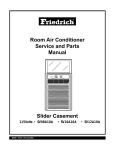
Window Air Conditioner
SVC MANUAL(General)
MODEL : Window
CAUTION
Before Servicing the unit, read the safety precautions in General SVC manual.
Only for authorized service personnel.
Air Conditioner Service Manual
CONTENTS
Safety Precautions ...........................................................................................................................3
Operation ..........................................................................................................................................6
Features .......................................................................................................................................6
Control Locations Function of Controls ........................................................................................6
Troubleshooting Guide.....................................................................................................................9
Piping System ..............................................................................................................................9
Troubleshooting Guide................................................................................................................10
Electrical Parts Troubleshooting Guide.......................................................................................12
Room Air Conditioner Voltage Limits..........................................................................................20
2 Window Air Conditioner
Safety Precautions
Safety Precautions
To prevent injury to the user or other people and property damage, the following instructions must be followed.
■ Incorrect operation due to ignoring instruction will cause harm or damage. The seriousness is classified by the following indications.
This symbol indicates the possibility of death or serious injury.
This symbol indicates the possibility of injury or damage to properties only.
■ Meanings of symbols used in this manual are as shown below.
Be sure not to do.
Be sure to follow the instruction.
Dangerous Voltage
1.1 Cautions in Repair
SAFETY PRECAUTIONS
1. When servicing the unit, set the main SWITCH to OFF and remove the
POWER SUPPLY cables.
2. Observe the original lead dress. If a short circuit is found, replace all parts
which have been overheated or damaged by the short circuit.
3. After servicing the unit, make an insulation resistance test to protect the customer from being exposed to shock hazards.
INSULATION RESISTANCE TEST
1. Unplug the power cord and connect a jumper between 2 pins (black and white).
2. The grounding conductor (green or green & yellow) is to be open.
3. Measure the resistance value with an ohm meter between the jumpered lead
and each exposed metallic part on the equipment.
4. The value should be over 1MΩ.
Be sure to disconnect the power cable plug from the plug socket before disassembling the equipment for a repair.Internal components and circuit boards are at
main potential when the equipment is connected to the power cables. This voltage is extremely dangerous and may cause death or severe injury if come in contact with it.
Service Manual 3
Safety Precautions
Do not touch the discharging refrigerant gas during the repair work.
The discharging refrigerant gas.The refrigerant gas can cause frostbite.
Release the refrigerant gas completely at a well-ventilated place first.
Otherwise, when the pipe is disconnected, refrigerant gas or refrigerating
machine oil discharges and it Can cause injury.
When the refrigerant gas leaks during work, execute ventilation. If the refrigerant
gas touches to a fire, poisonous gas generates. A case of leakage of the refrigerant and the closed room full with gas is dangerous because a shortage of oxygen occurs. Be sure to execute ventilation.
When removing the front panel or cabinet, execute short-circuit and discharge
between high voltage capacitor terminals. If discharge is not executed, an electric shock is caused by high voltage resulted in a death or injury.
Do not turn the air-conditioner ON or OFF by plugging or unplugging the power
plug. There is risk of fire or electrical shock.
Do not use a defective or underrated circuit breaker. Use the correctly rated
breaker and fuse. Otherwise there is a risk of fire or electric shock.
Install the panel and the cover of control box securely. Otherwise there is risk of
fire or electric shock due to dust, water etc.
Indoor/outdoor wiring connections must be secured tightly and the cable should
be routed properly so that there is no force pulling the cable from the connection
terminals. Improper or loose connections can cause heat generation or fire.
Do not touch, operate, or repaire the product with wet hands. Hoding the plug by
hand when taking out. Otherwise there is risk of electric shock or fire.
Do not turn on the breaker under condition that front panel and cabinet are
removed.
Be sure to earth the air conditioner with an earthing conductor connected to the
earthing terminal.
Conduct repair works after checking that the refrigerating cycle section has
cooled down sufficiently. Otherwise, working on the unit, the hot refrigerating
cycle section can cause burns.
4 Window Air Conditioner
Safety Precautions
Do not tilt the unit when removing panels. Otherwise, the water inside the unit
can spill and wet floor.
Do not use the welder in a well-ventilated place. Using the welder in an enclosed
room can cause oxygen deficiency.
Be sure to turn off power switch before connect or disconnect connector, or parts
damage may be occurred.
1.2 Inspections after Repair
Check to see if the power cable plug is not dirty or loose. If the plug is dust or
loose it can cause an electrical shock or fire.
Do not use a joined power cable or extension cable, or share the same power
outlet with other electrical appliances. otherwise, it can cause an electrical shock,
excessive heat generation or fire.
Do not insert hands or other objects through the air inlet or outlet while the product is operating. There are sharp and moving parts that could cause personal
injury.
Do not block the inlet or outlet of air flow. It may cause product failure
Check to see if the parts are mounted correctly and wires are connected.
Improper installation and connections can cause an electric shock or an injury.
Check the installation platform or frame has corroded. Corroded installation platform or frame can cause the unit to fall, resulting in injury.
Be sure to check the earth wire is correctly connected.
After the work has finished, be sure to do an insulation tset to check the resistance is 2[Mohm] or more between the charge section and the non-charge metal
section (Earth position). If the resistance value is low, a disaster such as a leak or
electric shock is caused at user’s side.
Check the drainage of the indoor unit after the repair. If drainage is faulty the
water to enter the room and wet floor.
Service Manual 5
Operation
Operation
Features
• Designed for COOLING ONLY.
• Powerful and whispering cooling.
• Slide-in and slide-out chassis for the simple installation and service.
• Side air-intake, side cooled-air discharge.
• Built-in adjustable THERMOSTAT
• Washable one-touch filter
• Compact size
• Reliable and efficient rotary compressor
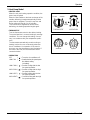
Control Locations Function of Controls
1. Cooling Only Model
• VENTILATION
The ventilation lever must be in the CLOSE position in order to maintain the best cooling
conditions.
When a fresh air is necessary in the room, set the ventilation lever OPEN position.
The damper is opened and room air is exhausted.
CLOSE
VENT
OPEN
• THERMOSTAT
Thermostat will automatically control the temperature of the room. Select a higher number for a cooler temperature in the room. The temperature is selected by positioning the knob to the desired position.
The 5 or 6 position is a normal setting for average conditions.
5
Off
• OPERATION
Off
( 0 ) : Turns the air conditioner off.
3
7
MED FAN
2
8
(
) : Permits the medium fan speed operation without
cooling.
4
6
1
Med
Fan
High
Cool
Low
Fan
9
Med
Cool
Low Cool
LOW FAN
(
) : Permits the low fan speed operation without
cooling.
Thermostat
) : Permits cooling with the high fan speed operation.
4
Operation
Auto Swing
Off
5
HIGH COOL (
MED COOL (
) : Permits cooling with the medium fan speed
operation.
6
7
2
8
9
Off
Med
Fan
3
1
On
High
Cool
Low
Fan
Med
Cool
Low Cool
LOW COOL (
) : Permits cooling with the low fan speed operation.
Thermostat
Operation
0
CAUTION: A slight heat odor may come from
the unit when first switching to HEAT after the
cooling season is over. This odor, caused by
fine dust particles on the heater, will disappear quickly.
6 Window Air Conditioner
0
Operation
2. Heat Pump Model
• HEATER LAMP
When the unit sets heating operation condition, the
green lamp is lighted.
When the frost settles on the heat exchanger of the
outside, defrosting is made automatically and the
green lamp is unlighted. The until it may hiss and
the fan motor will stop for 1 to 10 minutes.
This should not be regarded as trouble. After
defrosting, the heating operation begins again.
• THERMOSTAT
Turn the thermostat control to the desired setting.
The central position is a normal setting for average
conditions. You can change this setting, if necessary, in accordance with your temperature preference.
The thermostat automatically controls cooling or
heating, but the fan runs continuously whenever
the air conditioner is in operation. If the room is
too warm, turn the thermostat control clockwise. If
the room is too cool, turn the themostat control
counterclockwise.
COOLER
T
EA
H
WARMER
0
COO
L
HEATER
THERMOSTAT
OPERATION
(TYPE1)
Heater
Warmer
Cooler
Thermostat
Operation
(TYPE2)
• OPERATION
OFF
(
LOW FAN (
LOW COOL (
HIGH COOL (
LOW HEAT (
HIGH HEAT (
) : Turns the air conditioner off.
) : Permits the low fan speed operation without cooling
(or heating).
) : Permits cooling with the low
fan speed operation.
) : Permits cooling with the high
fan speed operation.
) : Permits heating with the low
fan speed operation.
) : Permits heating with the high
fan speed operation.
Service Manual 7
Operation
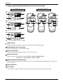
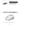
3. Cooling and Heating Model with Remote Control and Touch Type
DISPLAY
REMOTE CONTROL
3
6
2
1
1
1
5
5
5
4
4
4
2 3
2 3
2
1
4
5
3
6
2
3
8
1
4
5
3
2
6
4
1
5
7
POWER BUTTON
Operation starts, when this button is pressed and stops when you press the button again.
OPERATION MODE SELECTION BUTTON
Select Cooling, Heating, or Fan mode with this button.
ON/OFF TIMER BUTTON
Set the time of starting and stopping operation. The timer is set by 1 hour.
FAN SPEED SELECTOR
Select the fan speed. Cooling Model: 3 steps {High[F3] ➔ Low[F1] ➔ Med[F2]➔ High[F3]... }
Heating Model: 2 steps {High [F2] ➔ Low[F1] ➔ High[F2]... }
ROOM TEMPERATURE SETTING BUTTON
Control the room temperature within a range of 16°C to 30°C. The room temperature will be adjusted by 1˚C 30min., and
by 2˚C 1 hour later.
6 SIGNAL RECEIVER
7 AUTO SWING
The vertical louver swings horizontally by the automatic system and stops when you press the button again.
8 Window Air Conditioner
Troubleshooting Guide
Troubleshooting Guide
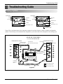
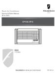
Piping System
CONDENSER
COIL
CONDENSER
COIL
FAN
FAN
CAPILLARY
TUBE
MOTOR
CAPILLARY
TUBE
MOTOR
COMPRESSOR
COMPRESSOR
BLOWER
BLOWER
EVAPORATOR COIL
EVAPORATOR COIL
: COOLING CYCLE
: HEATING CYCLE
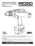
Figure 32 is a brief description of the important components and their function in what is called the refrigeration
system. This will help you to understand the refrigeration cycle and the flow of the refrigerant in the cooling cycle.
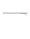
ROOM AIR CONITIONER
CYCLE OF REFRIGERATION
EVAPORATOR COILS
CONDENSER COILS
COMPLETE LIQUID
BOIL OFF POINT
COOLED
AIR
SUCTION LINE
COOL LOW PRESSURE VAPOR
VAPOR INLET
HOT
DISCHARGED
AIR
ROOM AIR HEAT LOAD
MOTOR
OUTSIDE COOLING
AIR FOR REFRIGERANT
PASS THROUGH
COMPRESSOR
OIL
LIQUID
PRESSURE
DROP
LIQUID OUTLET
(LIQUID REFRIGERANT)
CAPILLARY TUBE
HIGH PRESSURE VAPOR
LIQUID REFRIGERANT
LOW PRESSURE VAPOR
Figure 33
Service Manual 9
Troubleshooting Guide
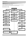
Troubleshooting Guide
In general, possible trouble is classified in two kinds.
The one is called Starting Failure which is caused from an electrical defect, and the other is ineffective Air
Conditioning caused by a defect in the refrigeration circuit and improper application.
Unit runs but poor cooling.
Ineffective Cooling
Check cold air circulation
for smooth flow.
Check outdoor coil
(heat exchanger) & the fan
operation.
Dirty indoor coil
(Heat exchanger)
Check gas leakage.
Check heat load
increase.
Clean condenser.
Not on separate circuit.
Malfunction of fan
Clogged of air filter.
Repair gas leak.
Replacement of unit if the
unit is beyond repair.
Obstruction at air outlet
Check inside gas
pressure.
Adjusting of refrigerant
charged.
Correct above trouble
Malfunction of compressor.
Check clogging in refrigeration circuit.
Repair clogging in refrigeration circuit.
10 Window Air Conditioner
Replacement of
compressor.
Satisfactory operation with
temperature difference of
inlet & outlet air ;
44~50°F(7~10°C)
Troubleshooting Guide
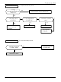
Fails to Start
Check of power source.
Check circuit breaker
and fuse.
Check of control switch
setting.
Gas leakage of feeler bulb
of thermostat
Check of control switch.
Compressor only fails to
start.
Fan only fails to start.
Improper wiring.
Drop of power voltage.
Improper thermostat setting.
Defect of fan motor
capacitor.
Defect of compressor
capacitor.
Loose terminal connection.
Capacitor check.
Irregular motor resistance
( ).
Irregular motor insulation
( ).
Improper wiring.
Replacement
Replacement of fan motor.
Irregular motor resistance (
)
Irregular motor insulation (
)
Regular but fails to start.
Replacement of compressor
(locking of rotor, metal).
Replacement of compressor
(Motor damaged)
Service Manual 11
Troubleshooting Guide
Electrical Parts Troubleshooting Guide
LWC1264PAG/PAN/PCG, LWC1264QAG/QAS, LWC126CBHK0, LWC126CGMM0/CBMM1/LWC096CBMK0
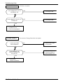
Possible Trouble 1
The unit does not operate.
Is the Trans input power
AC 220/240V?
NO
•• Check
Check the
the Fuse.
Fuse.
•• Check
the
Check thewiring
wiringdiagram.
diagram.
YES
Is the Trans output power
about AC 13V?
NO
Is shorted the Trans. output?
• Check the Main
PCB pattern.
YES
YES
Is output Voltage of IC01D
DC 12V?
NO
• Exchange the Trans.
NO
• Exchange D02D~D05D.
• Exchange IC01D.
YES
Is output Voltage of IC02D
DC 5V?
NO
• Exchange IC02D.
YES
Is the reset circuit all right?
(The No.16 of
Micom is 5V.)
NO
• Exchange IC01A, C02A.
YES
Is the
connection between
Main and Display all right?
NO
• Connect connector
exactly.
NO
• Check the PCB
pattern.
YES
Is the voltage No.20 of Micom
DC 5V?
YES
Exchange Main PCB Ass'y.
12 Window Air Conditioner
Troubleshooting Guide
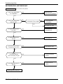
Possible Trouble 2
The compressor does not operate.
Is setting
Temp. set lower than Room
Temp.-0.5°C?
NO
• Select the setting Temp. to lower Number.
YES
NO
Is the voltage No.11
of IC01M 0V?
Is the voltage N0.6 of
IC01M DC 5V?
YES
YES
• Check the RY-COMP.
• Check the wiring
Diagram.
• Exchange IC01M.
NO
Is the Unit for 3 minutes
delay?
NO
YES
• Wait 3 Minutes.
• Exchange MAIN
PCB Ass'y.
Possible Trouble 3
The compressor always operate.
Is the wire connection of
RY-COMP all right?
NO
• Connect LEAD Wire to
RY-COMP again.
YES
• Check the RY-COMP.
Service Manual 13
Troubleshooting Guide
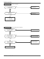
Possible Trouble 4
FAN does not operate.
Is the voltage NO.2 or 3 or 4
of IC01M DC 5V?
NO
• Exchange IC01M.
YES
Is the voltage NO.13 or 14 or 15
of IC01M 0V?
NO
• Exchange IC01M.
YES
• Check the RY-Hi or
RY-Med or RY-Lo.
• Check the wiring diagram.
Possible Trouble 5
The function of Energy Saver does not operate.
Is the Knob of SW1
set to left position?
NO
• Set the Knob of SW1
to left position.
YES
Is the voltage No.1 of
CN-DISP1 of Main PCB
Ass'y DC 5V?
YES
• Reference to
OWNER'S MANUAL.
14 Window Air Conditioner
NO
• Check the SW1.
• Check the pattern of
Main & Display PCB.
Troubleshooting Guide
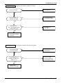
Possible Trouble 6
Remote controller does not operate.
Is the voltage of Battery
about over 2.3V?
NO
• Exchange the battery.
YES
Is the voltage No.10
of CN-DISP2 on Main PCB
Ass'y DC 5V?
NO
••Check
Checkthe
thePCB
PCBpattern.
pattern.
YES
NO
Is the connection of
CN-DISP2 all right?
• Connect connector to
CN-DISP2 exactly.
YES
• Exchange Receiver Ass'y.
Possible Trouble 7
It displays abnormally on display PCB Ass’y.
Is the IC01G all right?
NO
• Exchange IC01G.
YES
Is the connection of
CN-DISP2 all right?
NO
• Connect connector
to CN-DISP2 exactly.
YES
Does the Q12G,
Q13G, Q14G operate normally
on main PCB Ass'y?
NO
• Exchange Q12G,
Q13G, Q14G.
YES
• Exchange the display
PCB Ass'y.
Service Manual 15
Troubleshooting Guide
LWC1264PBG/PHG, LWC1264VBS/QBG
Possible Trouble 1
The unit does not operate.
Is the Trans output power
AC 220V/240V?
NO
• Check the Fuse.
• Check the wiring diagram.
YES
Is the Trans output power
about AC 13V?
NO
YES
Is shorted the Trans. output?
NO
• Check the Main
PCB pattern.
YES
• Exchange the Trans.
Is output Voltage of IC2
DC 12V?
NO
• Exchange BD1.
• Exchange IC2.
YES
Is output Voltage of IC3
DC 5V?
NO
• Exchange IC3.
YES
Is the reset circuit all right?
(The No.16 of IC1 is 5V.)
NO
• Exchange IC4, C07.
YES
Is the
connection between
Main and Display all right?
NO
• Connect connector
exactly.
NO
• Check the PCB
pattern.
YES
Is the voltage No.20 of IC1
DC 5V?
YES
Exchange Main PCB Ass'y.
16 Window Air Conditioner
Troubleshooting Guide
Possible Trouble 2
The compressor does not operate.
Is setting
Temp. set lower than Room
Temp.-0.5°C?
NO
• Select the setting Temp. to lower Number.
YES
Is the voltage No.10
of IC7 0V?
NO
Is the voltage N0.7 of
IC 7 DC 5V?
YES
NO
Is the Unit for 3 minutes
delay?
NO
YES
YES
• Check the RY-COMP.
• Check the wiring
Diagram.
• Exchange IC7.
• Wait 3 Minutes.
• Exchange MAIN
PCB Ass'y.
Possible Trouble 3
The compressor always operate.
Is the wire connection of
RY-COMP all right?
NO
• Connect LEAD Wire to
RY-COMP again.
YES
• Check the RY-COMP.
Service Manual 17
Troubleshooting Guide
Possible Trouble 4
FAN does not operate.
Is the voltage NO.2 or 3
of IC7 DC 5V?
NO
• Exchange IC1.
YES
Is the voltage NO.14 or 15
of IC7 0V?
NO
• Exchange IC7.
YES
• Check the RY-High or
RY-Low.
• Check the wiring diagram.
Possible Trouble 5
Remote controller does not operate.
Is the voltage of Battery
about over 2•3V?
NO
• Exchange the battery.
YES
Is the voltage No.7
of CN-DISP2 on Main PCB
Ass'y DC 5V?
NO
••Check
Checkthe
thePCB
PCBpattern.
pattern.
YES
Is the connection of
CN-DISP2 all right?
YES
• Exchange Receiver Ass'y.
18 Window Air Conditioner
NO
• Connect connector to
CN-DISP2 exactly.
Troubleshooting Guide
Possible Trouble 6
It displays abnormally on display PCB Ass'y.
Is the IC6 all right?
NO
• Exchange IC6.
YES
Is the connection of
CN-DISP1 all right?
NO
• Connect connector
to CN-DISP1 exactly.
YES
Does the TR1,
TR2, TR3 operate normally
on main PCB Ass'y?
NO
• Exchange TR1,
TR2, TR3.
YES
• Exchange the display
PCB Ass'y.
Possible Trouble 7
The function of Auto Restart does not operate.
Is the Knob of SW1
set to left position?
NO
• Set the Knob of SW1
to left position.
YES
Is the voltage No.3 of
CN-DISP2 of Main PCB
Ass'y DC 5V?
NO
• Check the SW1.
• Check the pattern of
Main & Display PCB.
YES
• Reference to
OWNER'S MANUAL.
Service Manual 19
Troubleshooting Guide
Room Air Conditioner Voltage Limits
NAME PLATE RATING
MINIMUM
MAXIMUM
220~240±10%
198V
264V
COMPLAINT
Fan motor will not run.
CAUSE
REMEDY
No power
Check voltage at outlet. Correct if necessary.
Power supply cord
Check voltage to rotary switch. If none, check power
supply cord. Replace cord if circuit is open.
Rotary switch
Check switch continuity. Refer to wiring diagram for
terminal identification. Replace switch if defective.
Wire disconnected or connection loose
Connect wire. Refer to wiring diagram for terminal
identification. Repair or replace loose terminal.
Capacitor (Discharge
capacitor before testing.)
Test capacitor.
Replace if not within ±10% of manufacturer's rating.
Replace if shorted, open, or damaged.
Will not rotate
Fan blade hitting shroud or blower wheel hitting
scroll. Realign assembly.
Units using slinger ring for condenser fan must have
1
/4 to 5/16 inch clearance to the base. If it hits the
base, shim up the bottom of the fan motor with
mounting screw(s).
Check fan motor bearings; if motor shaft will not
rotate, replace the motor.
Fan motor runs
intermittently
Revolves on overload.
Check voltage. If not within limits, call an electrician.
Test capacitor.
Check bearings. Does the fan blade rotate freely?
If not, replace fan motor.
Pay attention to any change from high speed to
low speed. If the speed does not change, replace the
motor.
Fan motor noise.
Compressor will not run,
but fan motor runs.
Fan
If cracked, out of balance, or partially missing,
replace it.
Turbo
If cracked, out of balance, or partially missing,
replace it.
Loose clamper
Tighten it.
Worn bearings
If knocking sounds continue when running or loose,
replace the motor. If the motor hums or noise
appears to be internal while running, replace motor.
Voltage
Check voltage.
If not within limits, call an electrician.
Wiring
Check the wire connections, if loose, repair or
replace the terminal. If wires are off, refer to wiring
diagram for identification, and replace. Check wire
locations. If not per wiring diagram, correct.
Rotary
Check for continuity, refer to the wiring diagram for
terminal identification. Replace the switch if circuit is
open.
20 Window Air Conditioner
Troubleshooting Guide
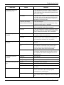
COMPLAINT
Compressor will not run,
but fan motor runs.
Compressor cycles on
overload.
Compressor cycles on
overload.
Compressor cycles on
overload.
Insufficient cooling or heating
Excessive noise
CAUSE
REMEDY
Thermostat
Check the position of knob If not at the coldest setting, advance the knob to this setting and restart unit.
Check continuity of the thermostat. Replace thermostat if circuit is open.
Thermistor
Check the TEMP control. If not at the lowest number,
set TEMP control to this setting and restart the unit.
Check the continuity of the thermistor. Replace the
thermistor if the circuit is open.
Capacitor (Discharge
capacitor before servicing.)
Check the capacitor.
Replace if not within ±10% of manufacturers rating.
Replace if shorted, open, or damaged.
Compressor
Check the compressor for open circuit or ground. If
open or grounded, replace the compressor.
Overload
Check the compressor overload, if externally mounted. Replace if open. (If the compressor temperature
is high, remove the overload, cool it, and retest.)
Voltage
Check the voltage.
If not within limits, call an electrician.
Overload
Check overload, if externally mounted.
Replace if open. (If the compressor temperature is
high, remove the overload, cool, and retest.)
Fan motor
If not running, determine the cause. Replace if
required.
Condenser air flow restriction
Remove the cabinet. inspect the interior surface of
the condenser; if restricted, clean carefully with a
vacuum cleaner (do not damage fins) or brush.
Clean the interior base before reassembling.
Condenser fins (damaged)
If condenser fins are closed over a large area on the
coil surface, head pressures will increase, causing
the compressor to overload. Straighten the fins or
replace the coil.
Capacitor
Test capacitor.
Wiring
Check the terminals. If loose, repair or replace.
Refrigerating system
Check the system for a restriction.
Air filter
If restricted, clean of replace.
Exhaust damper door
Close if open.
Unit undersized
Determine if the unit is properly sized for the area to
be cooled.
Turbo or fan
Check the set screw or clamp. If loose or missing,
correct. If the turbo or fan is hitting air guide,
rearrange the air handling parts.
Copper tubing
Remove the cabinet carefully and rearrange tubing
not to contact cabinet, compressor, shroud, and barrier.
Service Manual 21
P/NO : MFL37825901
JANUARY, 2007