1
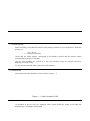
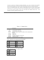
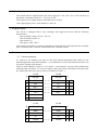
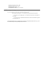
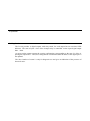
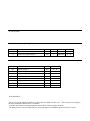
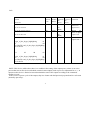
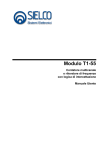
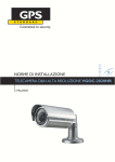
Digital module relay D1-20 User Manual Digital module relay D1-20 User Manual Sielco Elettronica srl by Edison 209-10019 Settimo Milanese (Milan) - Italy www.sielcoelettronica.com 1 Table of Contents 1 Installation 1.1 Checking the package 1.2 Dimensions 1.3 Method of attachment 1.4 Physical Description of the module 1.5 Supply 1.6 Digital outputs 1.7 Serial communication 1.7.1 Serial link 1.7.2 Communication Protocol 1.7.3 Identification 1.7.4 Serial connection cable 1.8 Earth wiring and shielding 2 Operation 2.1 Application A List of ports A.1 Numeric gates (Holding Registers) A.2 Digital gates (coils) A.2 Digital gates (coils) 1 Installation 1. 1 Check the Box Before installing, verify that the contents of the package conforms to your requirement. Inside the package are: - No. 1 D1-20 n ° 1 instruction manual Check that the model number corresponds to the number ordered and the manual edition corresponding to the year of purchase. The D1 series modules are covered by a one year warranty except for damages caused by tampering or wrong wiring. For the purchase date The label on the back of the modules. 1. 2 Dimensions The dimensions of the modules D1-20 are shown in figure 1 .1. Figure 1. 1 - Size of module D1-20 1. 3 Method of attachment All products in the D1 series are equipped with a plastic holder for fixing on rail DIN EN normalized by a shielding screen-printed. On the cover there are schematic mounting indications; gray areas are shown in the interface circuits inside the module, in yellow the sensors and actuators used to be connected externally. The cover serigraph provides only a general wiring diagram and can not show all the possible connection cases, it is therefore necessary, before activating the module, carefully read this manual. Do not exert excessive pressure on the cover and remove the module from the rail. remember to do these operations with power off. 1. 4 Physical module description Figure 1. 2 - Diagram D1-20 [C1] [C2] [M1] DIPSW Led LA Led LM Led TX RX LED Led UD Description Connector for connecting serial RS422/485 +24 Vdc power connector Terminal block relay outputs Selection dipswitch and device address of the communication protocol Supply led Led by selfLed data transmitted over the serial Led Received data Led by the physical state outputs [C1] - Connector for connecting serial RS422/485 RS422 RS485 1 RX- 1 NC 2 RX + 2 NC 3 TX- 3 TX-/RX- 4 TX + 4 TX + / RX + [C2] - Connector for power supply 24 VDC ALIM 1 +24 VDC 2 FIELD GND 3 MECH. GND Also 1. 5 Power Supply The module must be supplied with a DC power supply 24 V DC (18V <Vcc <36V) via the [C2] and absorb a maximum current Icc = 75 mA at 24 Vdc. The negative power supply must be connected to pin 2 of [C2]. After supplying the power, check that the LA led is lit. 1. 6 Digital Outputs The D1-20 is equipped with 8 relay exchange with suppression diode with the following characteristics: - Max switching voltage: 60 Vdc / 125 Vac - Max switching current: 2A - Max current: 1A - Max power: 30W / 60VA Each output corresponds to a triplet of terminals for which the first signal represents the "normally open" according to the "common" and the third is the "normally closed". 1. 7 Serial communication 1. 7. 1 Serial connection To connect to D1 modules, you must use the serial interface RS422/485 that usually are not standard equipment in personal computers. As an alternative to serial cards internal converters can be used for external serial interface. SIELCO ELECTRONIC produces C1-25 model, a serial interface converter RS232-RS422/485 with triple optical isolation. To use it you simply connect it by cable to the RS232 serial port of the PC (COM) and connect it to the [C1] D1-20 according to Table 1 .1. N ° 1 C1-25 D1-20 RS-422 RS-422 GND GND N ° 2 2 RX- TX- 3 C1 3 RX + TX + 4 C1 4 TX- RX- 1 C1 5 TX + RX + 2 C1 6 0V 7 +24 V GND N ° 2 C2 N ° 1 C1-25 D1-20 RS-485 RS-485 GND C2 2 nc nc 1 C1 3 nc nc 2 C1 4 TX-/RX- TX-/RX- 3 C1 5 TX + / RX + 6 0V 7 +24 V TX + / RX + 4 C1 Table 1. 1 - Connecting C1-25 - D1-20 (RS 422/485) The modules D1-20 are provided with configurable serial interface RS422/485, normally configured as RS485. To change the configuration, simply remove the protective cap and move the jumper at the top left on the card. 1. 7. 2 Communication Protocol The communication protocol software is realized according to Modbus ASCII or RTU: protocol selection is via the selector of dipswitch n ° 3 (RTU = ON, OFF = ASCII). The baud rate selection is made via the selectors # 2 dip switch (ON = 19200, 9600 = OFF). ASCII protocol Baud rate Data bits Parity bit Stop bit 9600/19200 7 even 1 RTU protocol features Baud rate Data bits Parity bit Stop bit 9600/19200 8 none 1 1. 7. 3 Identification The device may be assigned an identification address between 1 and 31, specified, according to the binary notation, using selector from 4 to 8 of dipswitch (Table 1 .2). ADDRESS 1 ON OFF X 2 3 4 5 BAUD PROT. 24 23 19200 RTU 9600 ASCII 2 6 7 8 2 21 20 Table 1. 2 - configuration using dipswitch NOTES The address 0 is reserved. The switch # 1 must be in the OFF position. 1. 7. 4 serial link cable Use a shielded cable with one (RS-485) or two (RS-422) twisted pair in compliance with EIA RS485, EIA RS-422, using the shield for ground. Cable Type: Belden 9841 (RS-485), 9842 (RS-422) Maximum attenuation of line: 6 dB Maximum capacity of line: 100 nf Maximum length: 1200 m Line Impedance: between 100 and 120 ohms 1. 8 Earth wiring and shielding For correct operation it is advisable to make the following ground: - the mechanical ground (pin # 3 of connector [C2]) goes directly to the ground; - the negative power supply (pin # 2 of connector [C2]) must be connected to a local earth; - on serial lines long or disturbed connect the mass of the serial channel to ground via a resistor 100 It 'important that the masses are brought to the ground in an independent manner and in any case is to avoid the sharing of traits grounding with power devices. 2 Operation 2. 1 Application The D1-20 provides 8 digital outputs with relay-made, for each output has an associated LED indicator. The state of open / close of the 8 output relay is controlled via the 8-port digital output DO1 .. DO8. At power-on the outputs assume the security configuration corresponding to the state "0" of the 8port digital output DO1 .. DO8, this configuration is maintained until the status of the digital port is not updated. The door "number of restart" is only for diagnostic use and gives an indication of the presence of electrical noise. A List of ports A. 1 Numeric gates (Holding Registers) Address 00 01 Description Restart number State relay digital outputs ID Rs DO Byte 1 1 Limits 0: 255 00h: FFh R/W R/W R/W A. 2 Doors digital (Coils) Address 00 01 02 03 04 05 06 Description Digital output 1 Digital output 2 Digital output 3 Digital output 4 Digital output 5 Digital output 6 Digital output 7 ID DO1 DO2 C3 C4 C5 C6 DO7 R/W R/W R/W R/W R/W R/W R/W R/W 07 Digital output 8 DO8 R/W Posts MODBUS The D!-15P can be interfaced with any system operator (HMI, SCADA, etc.)., Able to operate according to the protocol Modbus Master (RTU or ASCHI). Avail the table below for programming the master driver on the operator interface. The table refers to a device connected to a serial port and uses the Modbus protocol in RTU versone. 1) Set the type of physical interface used (RS485 or RS422) By moving the appropriate jumper under the hood. 2) The dip switches set on the device that must correspond to configurazone modbus set to the supervisor are: - Device Number: (Example 01) (dipswitch n 8 = ON, 3-4-5-6-7 - Off) Modbus type used (RTU or ASCHI, in the example RTU) (dipswitch 3 to ON for RTU) Baud rate used: (9600 or 19200, in the example 9600) (dipswitch n. 2 to OFF for 9600) .. 3) Each interface modbus supervision must be configured with the same parameters. (Usually found in the configuration screen on the Modbus serial line) 4) In addition, at the level of supervisor might have to be sure that the number of active logical channel (eg COM port number) corresponds physically to the serial to which the device is connected. As if you have a PC with a USB serial port, it is connected to its USB converter / RS422-485, you must obtain by reading it from the control panel of the PC COM port number (virtual) address to which the Modbus messages. 5) The messages to be sent to the device and the control of their answers must be in accordance with the table below. Hoding registers Mess modbus. Posted Modbus Variable Variable Function address read from written to performed Fuction the device the device code Received 01 03 00 01 00 01 D5 CA 01 03 02 00 04 F8 FF 01 06 00 03 30001 06 30001 06 30001 Reads the status of all 8 digital outputs 255 01 00 255 begin_of_the_skype_highlighting 01 06 00 01 00 GRATIS end_of_the_skype_highlighting 98 FF 4A 01 06 00 01 00 98 FF 4A 01 06 00 01 00 19 19 C0 01 06 00 01 00 19 19 C0 NOTE 1 The outputs are activated in the following order: u8 (OFF) u7 (OFF) u6 (OFF) u5 (ON) u4 (ON) u3 (OFF) u2 (OFF) u1 (ON) 25 Writes the status of all 8 outputs and digital As the previous case. The tag is in decimal numeric value. The transcoding device in binary and executes the command. NOTE 1 Coils Mess modbus. Posted Variable read from Fuction Modbus the code address device 01 10000 Received 01 01 00 00 00 01 FD CA 01 01 01 01 90 48 01 (HEX) 01 01 00 01 00 01 0A AC 01 10001 01 01 01 00 51 88 01 05 Variable Function written to performed the device Law lostato dellì'uscota 1 digital active Reads the status of digital output 2 off 00 (HEX) 00 02 05 10002 1 Enable the output state 3 begin_of_the_skype_highlighting 01 05 00 02 GRATIS end_of_the_skype_highlighting FF 00 2D FA 01 05 00 02 begin_of_the_skype_highlighting 01 05 00 02 GRATIS end_of_the_skype_highlighting FF 00 2D FA NOTE: This device, unlike other, there is no conflict in the setting of the output ports, as there is an active process that runs on the device and which controls lostato outputs (such as provesso adjustment for ex.). In questocaso the device is limited to run and maintain the state of the outputs according to the commands modbus rivevuti. In the event of a power cycle of the outputs, they lose lostato who had previously reported and in a safe state (normally open relay). 1