1
GE Consumer & Industrial
Technical Service Guide
February 2006
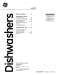
GE ProfileTM
Dishwasher
PDW8900 Series
PDW9700 Series
PDW9900 Series
31-9137
GE Appliances
General Electric Company
Louisville, Kentucky 40225
IMPORTANT SAFETY NOTICE
The information in this service guide is intended for use by
individuals possessing adequate backgrounds of electrical,
electronic, and mechanical experience. Any attempt to repair a
major ap pli ance may result in personal injury and property
damage. The manufacturer or seller cannot be responsible for the
interpretation of this information, nor can it assume any liability in
connection with its use.
WARNING
To avoid personal injury, disconnect power before servicing
this prod uct . If electrical power is required for diagnosis or test
purposes, disconnect the power immediately after performing the
necessary checks.
RECONNECT ALL GROUNDING DEVICES
If grounding wires, screws, straps, clips, nuts, or washers used to
complete a path to ground are removed for service, they must be
returned to their original position and properly fastened.
GE Consumer & Industrial
Technical Service Guide
Copyright © 2006
All rights reserved. This service guide may not be reproduced in whole or in part
in any form without written permission from the General Electric Company.
–2–
Table of Contents
Active Vent ........................................................................................................................................................................... 28
Circulation Pump and Motor .......................................................................................................................................30
Component Locator Views ...........................................................................................................................................10
Control Features ................................................................................................................................................................ 6
Control Module................................................................................................................................................................... 27
Customer Purge of the Bulk Dispenser Tank ....................................................................................................... 18
Demo Mode ......................................................................................................................................................................... 26
Detergent/Rinse Module................................................................................................................................................ 19
Dishwasher Components.............................................................................................................................................. 12
Door Interlock Switch...................................................................................................................................................... 19
Door Panel............................................................................................................................................................................ 12
Door Spring Installation. ................................................................................................................................................ 31
Drain System ...................................................................................................................................................................... 24
Factory Test Mode............................................................................................................................................................ 33
Factory Test Mode............................................................................................................................................................ 33
Fan (PDW9700 and PDW9900 Series) ..................................................................................................................... 28
Fill Funnel .............................................................................................................................................................................. 21
Heating Element................................................................................................................................................................ 22
Introduction ......................................................................................................................................................................... 5
Keypad Assembly ............................................................................................................................................................. 13
Lower Spray Arm, Fine Filter, and Inlet Cover ...................................................................................................... 21
Main Conduit ....................................................................................................................................................................... 21
Middle Spray Arm ............................................................................................................................................................. 20
Nomenclature. ................................................................................................................................................................... 4
Schematics and Strip Circuits .....................................................................................................................................34
Service Mode ...................................................................................................................................................................... 32
Single Rack WashTM.......................................................................................................................................................... 29
SmartDispenseTM ............................................................................................................................................................... 15
Smart Fill System. ............................................................................................................................................................. 24
Turbidity Sensor ................................................................................................................................................................ 23
Upper Spray Arm .............................................................................................................................................................. 21
Using the Dishwasher with the Upper Rack Removed.................................................................................... 20
Warranty for 2005 Product..........................................................................................................................................36
Warranty for 2006 and Later Product .................................................................................................................... 37
Wash Cycles........................................................................................................................................................................ 26
Water Hardness Test and Calibration ..................................................................................................................... 14
Water Valve and Flood Switch....................................................................................................................................25
Water Valve Test ............................................................................................................................................................... 25
Wax Motor and Magnet. ............................................................................................................................................... 30
–3–
Nomenclature
Model Number
P D W 9 9 8 0 L 0 0 S S
Brand
P = Profile
E = General Electric - NATM
G = General Electric
Product Type
CD = Counter Top
SD = Standard
SM = Spacemaker
RF = Retrofit
Exterior Color
BB = Black
II = Requires Custom Panel
and Handle
SS = Stainless Steel
WW = White
DW = Dishwasher
SC = Convertible
SS = Compact (18 in.)
HD = Home Depot Derivative
Engineering Model Suffix
Model Designator
Designates features – the higher
the number, the more features.
Nomenclature
Model Year Designator
Serial Number
The first two characters of the serial number
identify the month and year of manufacture.
Example:
AL123456S = January, 2006
The serial plate of your dishwasher
is located on the tub wall just inside
the door jam.
The mini-manual is located behind
the toe plate.
A - JAN
D - FEB
F - MAR
G - APR
H - MAY
L - JUN
M - JUL
R - AUG
S - SEP
T - OCT
V - NOV
Z - DEC
–4–
2006 - L
2005 - H
2004 - G
2003 - F
2002 - D
2001 - A
2000 - Z
1999 - V
1998 - T
1997 - S
1996 - R
1995 - M
The letter designating
the year repeats every
12 years.
Example:
T - 1974
T - 1986
T - 1998
Introduction
The new GE Profile PDW8900 Series, PWDW9700 Series, and PDW9900 Series dishwashers incorporate the
following new features for 2005:
•
SmartDispenseTM - A bulk liquid detergent dispense assembly is introduced with this dishwasher.
It consists of a dispense reservoir mounted within the inner door panel, a liquid level sensor connected to a Low Detergent LED on the control panel, and a positive displacement pump to inject
the optimal amount of detergent into the dishwasher during each cycle. A water hardness selection mode permits the calibration of the location's water hardness.
•
Single Rack WashTM - In addition to the two rack wash cycles, this GE Profile dishwasher has a
Single Rack Wash which bypasses the lower spray arm, directing the cleaning power to the upper rack only. Water is dispensed from the middle and upper wash arms only.
•
Smart Fill - The wash system has been changed to a low flow design. The wash, dry, and noise
performance have all been improved. Smaller jets on the spray arms require less water to keep
the pump primed. Less water allows the Calrod to heat the water to a higher temperature, improving both wash and dry performances.
•
Angled Rack Dry - A new top rack features two adjustable-angle dividers. This prevents rinse
water from puddling, allowing it to run off the bottoms of stemware, glasses, and cups.
–5–
Control Features
Throughout this manual, features and appearance may vary from your model.
PDW8900 Series
1
2
6
3
5
4
PDW9700 Series and PDW9900 Series
ANTI-BACTERIAL
COOKWARE
NORMAL
2
SPEED CYCLE
CHINA CYCLE
PLASTIC CYCLE
1
5
Smart Dispense
SINGLE RACK WASH
RINSE ONLY
LOW DETERGENT
SENSING
WASHING
3
4
DRYING
SANITIZED
CLEAN
6
Control Settings
1
Status Indicator Lights (Indicators vary by models)
The Status display tells you what is happening while the dishwasher is in operation and may flash,
indicating a malfunction. The lights will come ON indicating the sequence of the dishwasher operation.
LOW DETERGENT Displayed when the SmartDispense needs to be refilled with liquid or gel automatic dishwasher
detergent.
SENSING Displayed while the Clean Sensor™ is measuring the amount of soil and temperature of water.
The dishwasher will adjust the selected cycle to achieve optimal performance.
WASHING Displayed during prewash, main wash and rinse periods.
DRYING Displayed during HEATED DRY.
SANITIZED Displayed when cycle has met sanitization conditions.
CLEAN Displayed when a wash cycle is complete.
2
Time Remaining Display (on some models)
During operation, the display shows the minutes remaining until the cycle is complete. The display may
adjust the remaining time while the Sensing light is on. The time displayed at the start of each cycle may
change from the factory setting as the unit customizes itself to home use. During a delay start, the
display will show hours of time remaining until the cycle starts.
–6–
p y
3
g
y
Selections
PDW8900 Series: Press the pad for the desired wash cycle.
PDW9700 and PDW9900 Series: Use the Arrow Pads
to scroll through the wash cycles.
NOTE: All cycle times and water usage information contained in the following section are approximate values only. Actual
results will depend on several factors, including but not limited to, inlet temperature, household water pressure, and turbidity
of the wash water.
The light above or next to the selected pad will be ON to indicate which WASH CYCLE has been selected.
ANTI-BACTERIA Heavy 7.8 gal., 105 min.
Medium 6.7 gal., 95 min.
Light 5.6 gal., 85 min.
This cycle raises the water temperature in the final rinse to sanitize your dishware. The cycle length will
vary depending on the temperature of your inlet water.
NOTE: The Anti-Bacteria cycle is monitored for sanitization requirements. If the cycle is interrupted
during or after the main wash portion or if the incoming water temperature is so low that adequate
water heating cannot be achieved, the sanitizing conditions may not be met. In these cases, the
sanitized light will not illuminate at the end of the cycle.
NOTE: NSF-certified residential dishwashers are not intended for licensed food establishments.
COOKWARE Heavy 8.9 gal., 80 min.
(POTS & PANS) Medium 7.8 gal., 70 min.
Light 6.7 gal., 60 min.
This cycle is meant for heavily soiled dishes or cookware with dried-on or baked-on soils.
This cycle may not remove burned-on foods. Everyday dishes are safe to be used in this cycle.
NORMAL WASH Heavy 7.8 gal., 75 min.
Medium 6.7 gal., 65 min.
Light 4.5 gal., 50 min.
This cycle is for medium/heavily soiled dishes and glassware.
SPEED CYCLE 6.7 gal., 35 min.
This cycle is for everyday dishes and glassware.
CHINA CRYSTAL 6.7 gal., 35 min.
This cycle is for lightly soiled china and crystal.
PLASTICS CYCLE Heavy 6.7 gal., 160 min.
Medium 5.6 gal., 150 min.
Light 4.5 gal., 130 min.
The longer time for this cycle includes a built-in drying portion that is specifically designed to reduce
the risk of melting plastic items and improve plastic drying. For removing red tomato-based stains,
GE recommends the use of Cascade® Plastic Booster™.
SINGLE RACK WASH Heavy 6.1 gal., 45 min.
Medium 5.1 gal., 35 min.
Light 4.1 gal., 30 min.
This cycle washes lightly soiled dishes on the upper rack only.
RINSE ONLY 2.3 gal., 10 min.
For rinsing partial loads that will be washed later. Do not use detergent with this cycle.
NOTE: On the PDW8900 Series models, the CHINA CRYSTAL/PLASTICS selector is a toggle pad; toggle the pad until
the desired cycle is indicated.
NOTE: This dishwasher is equipped with a CleanSensor™ with automatic temperature control; therefore, cycle length and
time may vary depending on soil and temperature conditions.
NOTE: Only the Anti-Bacteria cycle has been designed to meet the requirements of Section 6, NSF 184 for soil removal
and sanitization efficacy.
–7–
4
Enhancements
The light above the selected pad will be ON to indicate which ENHANCEMENT has been selected.
DELAY HOURS You can delay the start of a wash cycle for up to 24 hours (depending on model). Press the
DELAY START pad to choose the number of hours you want to delay the start of the cycle; then
press START/RESET.
After closing the door, the machine will count down and automatically start at the correct time.
NOTE: To cancel the DELAY START selection before the cycle begins, press the DELAY START
pad until the display shows the estimated cycle time for the selected cycle in minutes.
ADDED HEAT When selected, the cycle will run longer with heating element on to improve both wash and dry
(EXTRA HOT WASH) performance.
NOTE: Cannot be selected with RINSE ONLY cycle.
PRE WASH For use with heavily soiled and/or dried-on, baked-on soils. This option MUST be selected PRIOR to
(on some models) starting the cycle. This option adds 15 minutes to the cycle time.
NOTE: Cannot be selected with RINSE ONLY cycle.
HEATED DRY Shuts off the drying heat option. Dishes will air dry naturally (PDW8900 Series) or
Light Off fan dry (PDW9700 and PDW9900 Series) to save energy.
HEATED DRY Turns the heating element on for fast drying. This will extend the total cycle time by 15 minutes for
the ANTI-BACTERIAL cycle, 8 minutes for the SPEED cycle, 15 minutes for the PLASTICS cycle,
30 minutes for the CHINA CRYSTAL cycle, and 38 minutes for all other cycles.
NOTE: Cannot be selected with RINSE ONLY cycle.
LOCK You can lock the controls to prevent any selections from being made. Or you can lock the controls
after you have started a cycle.
Children cannot accidentally start dishwasher by touching pads with this option selected.
To unlock the dishwasher controls, press and hold the HEATED DRY pad for 3 seconds. To lock the
dishwasher, press and hold the HEATED DRY pad for 3 seconds. The light above the LOCK pad
will turn off.
RESET To change a cycle after washing starts…
PDW8900 Series: Touch the START/RESET pad to cancel the cycle. The START/RESET light will
flash while the water is pumped out if needed. This takes approximately 2 minutes.
PDW9700 and PDW9900 Series: Open the door slowly to prevent splash-out. Touch the
START/RESET pad to cancel the cycle. If the START/RESET light is flashing, close the door
until the water pumps out (this takes approximately 2 minutes) and the light stops flashing.
When the light stops flashing, the dishwasher can be reprogrammed and restarted.
–8–
5
Start
PDW8900 Series
Close the dishwasher door and select the cycle and desired enhancements. Touch the START/RESET pad to begin the
cycle. Water fill begins immediately, and approximately 60 seconds later the wash action begins.
When the dishwasher door is fully closed, the control panel lights will display the last settings you selected. If you don’t
want to change any of the settings, simply touch the START/RESET pad to begin the cycle.
If the door is closed, the indicator lights will turn off if the START/RESET pad is not selected within 5 minutes. To activate
the display, open and close the door or press any pad.
PDW9700 and PDW9900 Series
After selecting the cycle and desired enhancements, touch the START/RESET pad to ready the dishwasher to begin the
cycle. Close the door to start the cycle or begin the DELAY START countdown. When the cycle starts, the water fill
begins and approximately 60 seconds later the wash action begins.
The dishwasher will always display your last selection and enhancements. If you don’t want to change the settings,
simply touch the START/RESET pad to ready the dishwasher and close the door to begin the cycle.
Also, if a power failure occurs NORMAL and HEATED DRY will automatically be programmed. Make any new selections
and touch the START/RESET pad to begin the new cycle.
If the door is opened, the indicator lights will turn off if the START/RESET pad is not selected within 5 minutes.
To activate the display, open and close the door or touch any pad.
6
Clean
PDW8900 Series
The CLEAN light is illuminated when the selected cycle and enhancements are complete. The light will stay ON until
a pad is pressed or the door is opened and then closed.
PDW9700 and PDW9900 Series
The CLEAN light is illuminated and a double beep will sound when the selected cycle and enhancements are complete.
You may remove the dishes at any time. Note the high-efficiency fan will run quietly for 30 minutes to 4 hours (depending
on selected cycle) after the CLEAN light is illuminated to continue drying the dishes. The fan can be turned off by opening
the door and pressing any keypad.
NOTE: To turn off the audible end-of-cycle signal (or re-activate it if it was previously disengaged), press the HEATED
DRY pad 5 times within 3 seconds. A triple beep will sound to indicate the end-of-cycle beep option has been toggled.
NOTE: If you are not using the SmartDispense and you want to turn the LOW DETERGENT LED light off, press the
ADDED HEAT pad 5 times within 3 seconds. You will hear three beeps, then the light will go off. You can turn the light
back on by pressing the ADDED HEAT pad 5 times within 3 seconds.
–9–
Component Locator Views
PDW8900 Series Shown
Inside Cabinet View
Left Side View
1
2
3
4
7
Fill Funnel
5
6
Fill Hose
8
Door Spring
Water Valve
1 - Upper Spray Arm, 2 - Middle Spray Arm , 3 - Lower Spray Arm, 4 - Hub,
5 - Filter Screen, 6 - Heating Element, 7 - Float, 8 - Smart Dispense Cap
PDW8900 Series Shown
Door View
(Door Panel and Eschtcheon Keypad
Assembly Removed)
Door Interlock Switch
Flapper (Active Vent)
Control Module
Active Vent Motor
Detergent Rinse Module
SmartDispenseTM Reservoir
Liquid Level Sensor
Positive Displacement Pump
Flood Switch
Junction Box
Circulation Pump
– 10 –
PDW9000 Series Shown
Door View (Door Panel Removed)
Door Interlock Switch
Active Vent Motor
Flapper (Active Vent)
Control Module
Fan Motor
Detergent Rinse Module
SmartDispense Reservoir
Liquid Level Sensor
Fan Conduit
Positive Displacement Pump
PDW8900 Series Shown
Bottom View
Front of Dishwasher
Flood Switch
Junction Box
Water Valve
Circulation Pump Motor
Wax Motor
Ball
Sump
Drain Pump
Drain Line Check Valve
Rear of Dishwasher
Heating Element
– 11 –
Turbidity Sensor
Dishwasher Components
Door Panel
PDW9700 Series and PDW9900 Series
Note: For top control dishwashers, there must be
1
/2-inch clearance between the top of the door and
the counter top.
PDW8900 Series
The door panel covers the main control board,
detergent cup, wire harness, Smart Dispense bottle,
Smart Dispense detergent sensor, and Smart
Dispense pump.
Escutcheon Keypad
Assembly Screws
The door panel covers the main control board,
detergent cup, vent fan, motor, louver, wire harness,
Smart Dispense bottle, Smart Dispense detergent
sensor, Smart Dispense pump, and door-interlock
switch.
The outer door panel is held in place by 12 screws
(5 Phillips head screws per side and two 1/4-in. hex
head screws at the bottom).
The outer door panel is held in place by 12 screws
(5 Phillips head screws per side and two 1/4-in. hex
head screws at the bottom). The esutcheon keypad
is held on by 4 screws.
Note: A ribbon cable connects the keypad
membrane (3-digit display on some models) to the
control circuit board. Due to the ribbon length, care
must be taken when removing the door panel to
ensure that the ribbon cable is not damaged.
Note: When removing the outer door panel, be
careful not to remove the 4 screws (2 per side)
holding the escutcheon to the door assembly.
Remove these only to gain access to the control
module, active vent, flapper, and door interlock
switch.
– 12 –
Keypad Assembly
PDW9700 Series and PDW9900 Series
Top control models have a membrane keypad that is accessed by removing the door panel. (see Door Panel.)
•
When removing the membrane keypad, peel the keypad from right to left.
•
When installing, make sure the membrane button areas and lights align with the keypad.
•
On models with an LED display, the display is held in place by 2 Phillips head screws.
Note: When replacing the keypad membrane, always run the Factory Test Mode to calibrate the keypad
membrane to the control board.
PADS
CONNECTOR PINS
1
11 & 17
11 & 16
11 & 15
12 & 15
12 & 16
12 & 17
13 & 15
Note: When troubleshooting, always check resistance between pins 18 and 19. The
membrane should read approximately 22K Ω.
When a control pad is pressed, continuity is present on the corresponding pins.
(See chart.) Example: If the HEATED DRY pad is pressed, you should have continuity
between pins 12 and 17. To locate pin numbers, note location of pin 1 for reference
point. (See illustration.)
PDW8900 Series
The keypad and ribbon cable are a permanent part
of the escutcheon and are replaced as a unit. To
remove the escutcheon keypad assembly, remove
the outer door panel and the 4 screws securing
the escutcheon keypad assembly. (See Door Panel,
PDW8900 Series.)
Active Vent Worm Gear
IMPORTANT: When assembling, the active vent
flapper must be closed before the escutcheon
keypad assembly is installed. Close the active vent
flapper by turning the worm gear clockwise by
hand. Failure to do so will cause a misalignment and
an increase in noise level.
– 13 –
SmartDispenseTM Calibration
Water Hardness Test and Calibration
Test Water Hardness
The automatic liquid dishwashing detergent
dispenser (SmartDispenseTM) dispenses the optimum
amount of detergent to clean the dishes. This
amount of detergent introduced during each cycle
is based on the soil level of the dishes and the
hardness of the water. Therefore, the correct water
hardness setting is very important for both optimum
cleaning of dishes and detergent usage.
The calibration process will differ slightly depending
on whether the dishwasher is front mount control
(PDW8000 series) or top mount control (PDW9000
series).
Front Mount Control (PDW8900)
Dishwasher must be in standby mode. Close and
latch the door. Press normal wash to illuminate the
lights on the control panel.
Prior to the first use, this dishwasher must be
calibrated for water hardness. This process requires
the use of a water hardness test strip (part #
WD01X10295). This part can by shipped by mail.
1. Press Cookware pad and Delay Hours pad
together and hold for 3 seconds.
2. The current hardness setting will be shown on
the Time Remaining display.
3. Enter the value from the test strip using the
Cookware pad to increase the value or the
Normal Wash pad to decrease the value.
The 4 light green stripes will change color. The
harder the water, the more stripes will change from
green to red.
4. Press the Start/Reset pad to return the
dishwasher to normal operation. The last
displayed value will be saved as the water
hardness value.
Water hardness should be tested following the
instructions on the test strip package shown above.
Note: If all stripes remain green after the test, the
outcome is "0 RED". The value to be entered into the
dishwasher is "1".
Convert the test reading according to the table
below.
Top Mount Control (PDW9700, PDW9900)
Dishwasher must be in standby mode. Press up
arrow to wake up control and illuminate the lights
on the control panel.
Water Hardness Test Strip Indication
Red Stripes on Strip
Value to Enter into Dishwasher
0
1
2
3
4
1
2
3
4
5
ANTI-BACTERIAL
COOKWARE
NORMAL
SPEED CYCLE
CHINA CYCLE
PLASTIC CYCLE
SINGLE RACK WASH
RINSE ONLY
Smart Dispense
LOW DETERGENT
SENSING
WASHING
DRYING
SANITIZED
CLEAN
1. Press the up arrow pad and Delay Hours
together and hold for 3 seconds.
2. The current hardness setting will be shown on
the Time Remaining display.
Note: 1 grain per gallon = 17.1 parts per million.
3. Enter the value from the test strip using the up
arrow pad to increase the value or the down
arrow pad to decrease the value.
4. Press the Start/Reset pad to return the
dishwasher to normal operation. The last
displayed value will be saved as the water
hardness value.
– 14 –
To remove the reservoir:
SmartDispenseTM
SmartDispenseTM is a bulk liquid detergent dispense
assembly consisting of the following components:
•
Detergent Reservoir - Mounted within the inner
door panel
•
Detergent Level Sensor - Connected to a Low
Detergent LED on the control panel
•
Positive Displacement Pump - Injects
the optimal amount of detergent into the
dishwasher during each cycle.
Note: Removing the reservoir access collar causes
structural damage to the collar. It must be replaced
with a new part # WD35X10059.
Remove the door panel. (See Door Panel.) Insert a
small flat-blade screwdriver into the slot in the side
of the retaining collar and push the screwdriver
handle counterclockwise while turning the reservoir
access collar counterclockwise a quarter turn.
Remove the retaining collar. Unplug the tube from
the reservoir outlet and disconnect the sensor from
the control module.
Detergent Reservoir
Note: The SmartDispenseTM system can only be
used with liquid or gel automatic dishwasher
detergent.
To fill the reservoir, push down on the cap covering
the reservoir to engage the ratchet, then turn it
counterclockwise to open.
Note: The dispenser tank comes as an assembly.
It includes the sensor with wire harness, gasket,
and retaining collar. The complete assembly part
number is WD35X10058.
Position the door at a 30 to 45 degree angle. Fill
the reservoir with a liquid automatic dishwasher
detergent until the detergent reaches the threads
of the reservoir access. The dispenser will hold
approximately 45 ounces of liquid dishwasher
detergent (about 1 to 2 months supply).
Place the cap on the reservoir access threads, push
down, then turn clockwise until the cap is tight.
– 15 –
Detergent Level Sensor
The SmartDispenseTM detergent level sensor consists
of a single level detection continuity sensor and
includes the following components:
• a grommet seal
• a low detergent LED indicator light
• a wire harness.
When the detergent in the reservoir drops below
the continuity sensor, a signal is sent to the control
board and the low detergent LED indicator light is
turned on. The light indicates 3 to 7 wash cycles left
before the detergent reservoir is completely empty.
Light will
turn on
when time
to refill
SmartDispense
LOW DETERGENT
SENSING
WASHING
DRYING
SANITIZED
CLEAN
Control 5 VDC to Sensor
The routing of the DC wiring from the tank is very
important. The 3 tape points on the tank keep the
DC wiring perpendicular to the AC harness wiring
running down across the front of the tank. (See tank
photo.)
Note: The Low Detergent LED may look like it is
illuminated when in fact it is not. An indicator that is
illuminated will be a bright red.
Tape Point
Note: If the SmartDispenseTM system is not being
used, the low detergent light can be turned off (or
on) by pressing the Added Heat pad 5 times within
3 seconds. There will be 3 audible beeps when the
light goes off.
Tape Point
Tank
The sensor is similar to the type used in several
automotive applications such as the windshield
wiper fluid reservoir.
Tape Point
Sensor and Gasket
The control takes a reading of the detergent level at
power up (when power is restored from an outage)
and each time the door is closed and latched.
Note: The dispenser tank, sensor with wire harness,
and gasket are only available as a complete
assembly (part # WD35X10058). They are shipped
with a new dispenser tank retaining collar.
The control outputs a pulsing 5 VDC analog signal
to the sensor and monitors the return voltage.
Changes in the quantity of detergent in the tank
change the amount of current drawn by the sensor.
Detergent Level Sensor Strip Circuit
J4-1
– 16 –
BRN/YELLOW
DETERGENT
SENSOR
RED
J4-3
Approximate Detergent Use
From
Detergent
Reservoir
Smart Dispense Dosage Amount
Dosage (ml)
To Detergent
Outlet
1
33
35.4
37.8
40.2
42.6
1
2
3
4
5
Soil Level
2
3
41
49
43.4
51.4
45.8
53.8
48.2
56.2
50.6
58.6
4
57
59.4
61.8
64.2
66.6
Smart Dispense Bottle Duration
Bottle Duration (wks)
1
2
3
4
5
Hardness
The SmartDispenseTM positive displacement pump
consists of a continuous flexible tube running from
the detergent reservoir to the inner door detergent
outlet. The tube runs around the inside edge of the
pump housing. A 3-roller impeller fits tightly into
the center of the pump housing with each of the
3 rollers squeezing the sidewall of the tube. As the
impeller is driven counterclockwise by the motor, it
squeezes out a predetermined amount of detergent
for each 1/3 revolution of the impeller.
Hardness
Positive Displacement Pump
Soil Level
1
10.3
9.6
9.0
8.4
8.0
2
8.3
7.8
7.4
7.0
6.7
3
6.9
6.6
6.3
6.0
5.8
4
5.9
5.7
5.5
5.3
5.1
To remove the pump
1. Remove the door panel. (See Door Panel.)
Pump
Housing
2. Remove 2 Phillips head screws from the lower
right side of the door edge to release the pump
bracket.
Impeller
3. Remove the grommet from the inner door panel
and unplug the tube from the reservoir outlet.
4. Disconnect the wires and remove the pump.
The dispenser pump operates on 120 VDC. During
each pre-wash cycle, the pump is energized for 5
seconds, dispensing 4ml of detergent.
The electronic control uses two inputs to determine
the total amount of detergent dispensed during the
main wash cycle:
•
•
Soil Level determined by the turbidity sensor
Water Hardness as calibrated for the location
A water hardness selection mode permits the
calibration of the water hardness for the location
at installation. (See Water Hardness Test and
Calibration.)
To determine the amount of detergent to dispense
during the main wash, the control uses the following
formula:
Positive Displacement Pump Strip Circuit
4ml x Number of Pre-washes
+ 25ml + Additional Quantity for Hardness
The additional quantity is a predefined quantity
of detergent based on the water hardness level
programmed into the control.
J2-1
ORANGE
BULK DETERGENT
PUMP
M
875 Ω
– 17 –
WHITE
Follow these steps carefully to have a successful
purge run.
Customer Purge of the Bulk Dispenser Tank
When to Purge the Bulk Dispenser Tank
Front Mount Controls (PDW8900)
Only liquid or gel automatic dishwashing detergent
can be used in the bulk dispenser. The dispenser
must be purged if the consumer puts hand
dishwashing detergent or a rinse agent in the
dispenser. These products will produce copious
amounts of suds, and water leaks will result every
time the dishwasher is run until the tank is emptied.
Top Mount Controls (PDW9700, PDW9900)
The dishwasher must also be purged if a liquid
dishwasher detergent containing chlorine
(like Cascade Pure Rinse Formula) and a liquid
dishwasher detergent containing enzymes (like
Cascade Complete) have been mixed in the
dispenser. When this happens, the chlorine destroys
the enzymes resulting in poor wash performance.
You can tell if the detergent contains chlorine
or enzymes by reading the content label on the
container.
A chemical reaction also takes place between the
chlorine detergent and the enzyme detergent which
causes the two liquids to coagulate and buildup
around the detergent level sensor. This build up may
prohibit the sensor from sending the low detergent
signal to the control board and the low detergent
light will not be illuminated when the bulk dispenser
is empty.
Consumer Purge Cycle
The consumer must enter Service Mode to activate
the purge cycle. The purge cycle fills the dishwasher
for 57 seconds, then energizes the dispenser pump
(instead of the main motor) continuously to drain
the bulk dispenser tank .
The purge cycle deselects all other options and
runs for 65 minutes. The consumer should run the
purge cycle 3 times, filling the dispenser tank with
water for the second and third cycles. Total time is
approximately 3 hours.
ANTI-BACTERIAL
COOKWARE
NORMAL
SPEED CYCLE
CHINA CYCLE
PLASTIC CYCLE
SINGLE RACK WASH
RINSE ONLY
Smart Dispense
LOW DETERGENT
SENSING
WASHING
DRYING
SANITIZED
CLEAN
1. Make sure Pre-wash, Added Heat, and Heated
Dry LEDs are off.
2. Press Heated Dry pad and Cookware pad
(down arrow pad on Top Mount Control models)
together for 3 seconds. All LEDs illuminate.
3. Press Added Heat pad and Normal pad (up
arrow pad on Top Mount Control models)
together for 3 seconds. The Anti-bacterial LED
illuminates.
4. Press Start pad one time.
5. Press Normal Wash pad and make sure Prewash, Added Heat and Heated Dry LEDs are off.
6. Press Start pad. Dishwasher will run a complete
cycle without the main motor running. Cycle is
complete when the clean light illuminates. This
should take approximately 60 minutes.
7. Open door and wipe up the excess detergent
from the door and tub.
8. Pour water on the door and tub where there is
detergent residue.
9. Remove SmartDispenseTM cap and fill tank with
water. Replace cap.
10. Repeat steps 1 through 9 one time.
11. Repeat steps 1 through 6. When the Clean LED
illuminates, the system is purged and ready to
be refilled with the correct detergent.
– 18 –
Detergent/Rinse Module
The door panel must be removed to access the
detergent/rinse module. (See Door Panel.)
The detergent rinse module is held in place by 6
Phillips head screws and 2 brackets.
3
Door Interlock Switch Strip Circuit
Disconnect
DETERGENT MODULE
J2-9
RED/YELLOW
WHITE
1200 - 2800 Ω
Bracket
Door Interlock Switch
The detergent/rinse module automatically
dispenses both the detergent and the rinse agent
at the appropriate times. The module is activated 2
times during a wash cycle. Detergent is dispensed
at the beginning of the main wash cycle and
rinse agent at the beginning of the final rinse. The
detergent/rinse module can be activated using the
Service Mode.
The door interlock switch opens the L1 circuit when
the door is open. The switch is replaced as an
assembly.
The door panel and escutcheon must be removed to
access the door latch switch. (See Door Panel.)
The door latch switch is held in place by 2 Phillips
head screws.
The first time the module is activated:
The lever slides up the right-hand path of the
connecting rod (1). This action releases the
detergent cover.
When deactivated (2), the lever returns down the
left-hand path and comes to rest under the notch in
the center of the connecting rod.
2
1
If the door is unlatched while running a wash cycle,
the cycle countdown will pause and the vent will
open. If unlatched for more than 15 seconds during
a wash cycle, the control will beep once every 15
seconds until the door is relatched.
At the second activation (3), the lever lifts the
connecting rod by the notch. This action lifts the
rinse dispenser plunger and releases the rinse
agent. When deactivated, the lever returns to its
original starting position.
Door Interlock Switch Strip Circuit
J2-10
BLK/WHITE
DOOR
INTERLOCK
NO
J2-11
– 19 –
BLK/WHITE
COM
BLK
Using the Dishwasher with the Upper Rack
Removed
Middle Spray Arm
1. Unsnap and remove the end cap on each side of
the rails.
1. Check holes in spray arm for bits of china, seeds,
and other foreign matter.
2. Check spray arms for rotation.
2. Pull the rack straight out and off the rails.
Removal and Replacement
3. Replace the end caps.
1. Pull upper rack all the way out.
4. Push the rails all the way back into the
dishwasher.
2. Remove plastic screw on bottom of middle
spray arm. This will allow the middle spray arm
and bearing to be removed.
Note: Install middle spray arm with spray jets facing
the upper rack. Place bearing between spray arm
screw and bottom of the middle arm.
5. Slide the shower nozzle attachment over the
spout.
6. The dishwasher is now ready for use.
Note: Always use the shower nozzle when the upper
rack is removed.
Note: If the upper rack experiences poor cleaning
problems, ensure the middle spray arm is turning
freely. If not, disassemble the middle spray arm and
clean the bearing surface, then reassemble.
– 20 –
Lower Spray Arm, Fine Filter, and Inlet Cover
Check the holes in spray arm for bits of china, seeds,
and other foreign matter. Also check the spray wash
arms for rotation. If soil is present, clean fine filter
screen.
The lower spray wash arm can be removed by
gently lifting and rotating it counterclockwise.
The nut hub can be removed by rotating it
counterclockwise.
Caution: Use care to avoid breaking the clip on the
hub when removing the main conduit from hub.
Note: When installing the fine filter, make sure the
drain port of the filter is engaged with the drain for
the fine filter.
Upper Spray Arm
Check the holes in spray wash arm for bits of china,
seeds, and other foreign matter. Also, check the
spray wash arms for rotation.
To remove the upper spray wash arm, remove the
upper rack (see Middle Spray Arm), then remove the
screw and upper spray wash arm.
Main Conduit
The main conduit supplies water to the middle and
upper spray wash arms.
Removal and Replacement
1. Pull upper rack all the way out.
2. Push the tab on the outer slide cap in and
remove the slide cap.
Lower
Spray Arm
3. Remove the upper rack.
4. Release the bottom conduit tab.
Main Conduit
Mounting Screw
5. Release 2 center conduit tabs and remove the
main conduit.
Main Conduit
Fine Filter
Drain Port
Drain For
Fine Filter
Nut Hub
Fine Filter
Assembly
Cover Inlet
Coarse Filter Hub
Main Conduit
Tab
Fill Funnel
The top section of the fill funnel separates from the
main body. The fill funnel body is held in place by a
nut (located on the inside of the dishwasher). Rotate
the nut counterclockwise to remove the main body.
There is a gasket seal between the fill funnel and
dishwasher tub. Make certain the gasket is seated
when reinstalling.
Float Dome
Nut
Gasket
– 21 –
It is normal for the stainless steel tub and the inner
door panel to retain water droplets even though the
dishes are dry.
Heating Element
The heating element can be activated using Service
Mode.
The dual-wattage heating element produces 875
watts during wash, to help heat the water, and an
effective wattage due to cycling of 700 watts during
the dry cycle.
It is normal for the heating element to cycle during
Heated Dry cycle. The control energizes the heating
element continuously for the first 6 minutes. The
control then cycles the heating element on for 60
seconds, and off for 60 seconds for the remainder of
the Heated Dry cycle.
Selecting Added Heat will energize the heater for
the entire time during the last prewash cycle and
the final rinse cycle. Circulation time during the
final rinse is increased 2.8 times the normal with this
option. If selected after the wash cycle has started,
the feature will not take effect until the beginning of
the next fill. This option is not available for the Rinse
Only cycle.
Heating Element Strip Circuit
HEATING ELEMENT
PURPLE
J2-6
J2-7
WHITE
PURPLE
The heating element nuts are located on the
underside of the washer, near the back. Ample
force is required to remove the nuts. Removing the
dishwasher from installation may be required.
Heating
Element
Water inlet temperature must be at least 120°F
for proper drying. Low water inlet temperature
will prevent proper convection air movement and
increase drying time substantially.
Heater
Grommet
If the problem is that the dishes are not drying
correctly, don’t overlook the rinse agent. A rinse
agent will improve the water sheeting action and
drying performance.
Tub
Nut
Heating Element
Support
– 22 –
The thermistor’s resistance has a negative
temperature coefficient. As the temperature
increases, the resistance goes down. At 75°F, the
resistance is approximately 9.9K Ω. At 140°F, the
resistance is approximately 2.8K Ω.
Turbidity Sensor
The turbidity sensor is located on the side of the
sump.
Note: When installing the turbidity sensor, align the
key on the sensor with the keyway on the sump.
Turbidity Sensor
Key
The turbidity sensor measures the amount of
suspended particles in the wash water in the sump.
The control sends the turbidity sensor a pulse width
modulated 5-volt signal for calibration and usage
during operation.
The control then receives an analog signal of
the sensed turbidity, which is processed by the
microprocessor.
The Service Mode is the most accurate way to test
the turbidity sensor circuit. The turbidity sensor
circuit contains the control module, wiring, and the
turbidity sensor.
Turbidity Sensor Strip Circuit
The baseline reading is taken during the first fill
when the sump water level is between the 1/4- to
3
/8-in. gap between the LED transmitter and the
receptor. Successive turbidity measurements
are supplied to the control module and used to
determine whether any prewash or rinse cycles can
be skipped. The sensing LED is on during all prewash
cycles and during the final rinse.
YELLOW/BLK
DK. BLUE
GRAY
ORANGE
NTC
1
2
3
4
Calibrating the Turbidity Sensor
Decisions are based on a comparison of clean
water measurements at the beginning of the first
fill, measurements taken at selected fills, and water
temperature. By measuring the turbidity level, the
control module can conserve energy on lightly
soiled loads by skipping unnecessary cycles.
When replacing the turbidity sensor, or if it has been
disconnected, always calibrate the turbidity sensor
to the control board.
Note: The calibration cycle MUST be entered within
2 minutes of power up.
Note: If the turbidity sensor circuit fails to open or
is shorted, the sensing LED on the control panel will
not light, and the unit will operate for the maximum
amount of time, using the maximum number of
wash and rinse fills for the selected cycle.
The turbidity sensor also contains the thermistor
for automatic temperature controlTurbidity Sensor
Test
Press the Normal pad (the up arrow pad on Top
Control Models) and the Cookware pad (the down
arrow pad on Top Control Models) for 3 seconds or
until all LEDs turn on.
The dishwasher will then perform a series of steps.
Once the drain cycle starts, calibration is complete
and the Start/Reset pad can be pressed to end the
calibration cycle. The dishwasher will continue to
pump out remaining water and cycle of.
– 23 –
Drain System
Smart Fill System
The drain system consists of the following
components:
• Auxiliary drain pump (includes motor and oneway check valve)
• Drain tube
• Check valve (in line with drain tube)
• Drain hose
The Smart Fill system consists of a new silent fill
hose design and electronicly controlled cavitation
sensing (adaptive fill).
The new fill hose design uses a rigid plastic tube
with rubber over mold at both ends. This smaller
diameter reduces water flow rate and fill noise. The
required water line pressure is still 20 to 120 psi.
The inlet cover prevents large particles from entering
the sump. Water entering the drain pump is not
filtered by the fine filter (metal) or by the sump filter
(plastic). The drain pump is mounted on the sump
and contains a one-way check valve. The drain
pump is controlled by the control module and can be
activated using Service Mode.
Fill Hose
Auxiliary Drain Pump strip Circuit
DRAIN PUMP
J2-8
RED
M
WHITE
30 Ω
The drain pump utilizes a 120V AC motor. The motor
should read approximately 30 Ω.
IMPORTANT: The drain system of this dishwasher
requires either a high drain loop or an air gap.
Installations without either a high drain loop or an
air gap will not perform properly.
32"
18" Min.
Min.
Air Gap
The cavitation sensing controls the amount of water
for each fill. The dishwasher fills for 57 seconds,
then the pump motor starts. The load on the motor
changes as water enters and exits the sump. The
electronic control monitors this change as motor
current fluctuation and continues to fill the tub until
the fluctuations are stable, assuring the sump is full.
Note: The maximum amount of time the electronic
control will energize the water valve is 95 seconds.
During a normal wash cycle, the water level in the
tub will cover the sump screen or be just to the rear
edge of the heater bracket. The dishwasher will fill
with approximately 1.2 gal. of water.
High Drain Loop
Water Level
Depending on the wash cycle selection, a complete
wash cycle will use between approximately 2.5 gal.
(Rinse Only) to 10.9 gal. (Cookware - heavy soil level).
– 24 –
Water Valve and Flood Switch
Water Valve Test
The water valve is a 120 VAC solenoid valve that is
switched on/off by the control module. The flood
switch acts as a safety switch ONLY and does not
control normal operation of the water valve. The
flood switch opens the L1 side of the water valve
circuit.
Note: The detergent pump will also operate during
the water valve test.
1. Attempt to activate water valve using Service
Mode. Pump out water as necessary using
Service Mode. If an intermittent failure is
suspected, activate water valve 5 times using
Service Mode. Water valve should stay on for 75
to 95 seconds per activation and should not turn
on and off during the 75 to 95 second activation
time. A normal fill will be approximately 1.2
gallons.
The switch is normally open. The weight of the
flood switch float holds the switch closed. The flood
switch will not stop the flow of water if the valve
sticks open from a mechanical failure.
The water valve can be replaced with the
dishwasher installed.
2. If the water valve is not operating properly or
water level is low, check the following:
WARNING: Disconnect power to dishwasher before
servicing water valve and flood switch.
•
Water valve, flood switch, flood switch float
and stem, transorb, and then main control.
The flood switch should open when the
water level is approximately 1/4-in. above the
base (bottom) of the float dome.
•
Resistance through the water valve solenoid
coil is 725 Ω to 1200 Ω.
•
Clogged screen in water valve.
The flood switch is held in place by 2 Phillips head
screws.
Flood Switch
Water Valve Strip Circuit
PDW9700 Series and PDW9900 Series
WATER VALVE
J2-5
PINK
FLOOD
SWITCH
C
The water valve is secured to the frame by 2 hex
head screws.
WHITE
YEL.
NO
725 - 1200 Ω
PPDW8900 Series
J2-5
Water Valve
Note: To prevent leaks after installation, ensure that
hose-to-valve connection is good and that clamp is
in place.
– 25 –
PINK
FLOOD
SWITCH
C
YEL.
NO
WATER VALVE
725 - 1200 Ω
WHITE
Demo Mode
•
Demo mode is entered by pressing the Cookware pad (down arrow pad on Top Control models) and
Added Heat pad simultaneously for 5 seconds.
•
When entered, the Normal and Added Heat LEDs blink for 3 seconds, and the active vent will close.
•
Pressing a pad will light the corresponding LED.
•
Pressing the Start/Reset pad will activate the main pump for 20 seconds, and each cycle LED will be lit in
sequence for 3 seconds (left to right).
•
The display will sequence 999, 888, 777, 666, 555, etc., before running the main pump.
•
The cycle will end after the main pump stops. The drain cycle will not be energized.
•
To exit the demo mode, the dishwasher must be disconnected from power.
Wash Cycles
CYCLE
MAX # OF
PRE-WASH
CYCLES
WASH
CYCLE
MAX #
RINSE
CYCLES
WASH TIME1
MIN
MAX
Normal Wash
3
1
3
36
99
Speed Wash
3
1
2
23
53
China Crystal
2
1
3
26
61
WASH TEMPERATURE
HEATED
DRY TIME
FAN ON TIME6
MIN
MAX
2
2
38+5
158
240
3
8
128
240
3
30
150
240
137
3
130
3
130
2
145
150
135
HEATED DRY W/O HEATED DRY
2
38
158
240
3
150
240
Pots & Pans
4
1
3
60
112
Sani Wash
3
1
3
36
115
130
158
15+15 4
Plastics
3
1
2
76
136
1402
1452
45/60 5
180
240
140
3
30
150
240
2
38
158
240
_
_
240
Glasses
2
1
3
26
61
150
3
3
130
2
140
Single Rack Wash
3
1
3
36
96
137
145
Rinse Only
2
0
0
9
11
_
_
Time is in minutes
Temperature is in degrees Fahrenheit
1.) Cycle times do not include water fill and drain
2.) Heater on in main wash and final rinse
3.) Heater on in all pre-washes, main wash, and all rinses
4.) Heated dry time and cool down time
5.) 45 minutes without heated dry, 60 minutes with heated dry
6.) Fan running time after cycle has completed
– 26 –
Control Module
The door panel must be removed to access the control module. (See Door Panel.) The main control is
considered a “smart” control, capable of learning the water temperature and turbidity characteristics of the
home.
It is normal for the cycle times to vary over a period of time from the factory default settings due to
temperature and water quality.
The control module is held in place by a single screw that secures the module to the right side of the inner
door panel. (The screw is located on the outside of the inner door panel.)
The module cover is held in place by 5 tabs (see arrows).
Screw
Control Module Board
J4
Note: When replacing
the control module,
always run the Factory
Test Mode to calibrate
the keypad membrane
and turbidity sensor to
the control board.
J10
J2
J7
J1
J5
J8
J1 - Power Supply X
J3
J2 - Heating Element, Circulation Pump, Drain Pump, Fan, Water Valve,
Detergent Module, Wax Motor, Bulk Detergent Pump
J3 - Turbidity/Temperature Sensor
J4 - Detergent Sensor
J5 -Active Vent
J7 - Keypad
J8 - 3-Digit Display
J10 - PQA
– 27 –
Note: This also applies to the Rinse Only cycle.
Since heated dry is not an option with Rinse Only,
the fan will run for approximately 4 hours before
turning off.
Active Vent
The active vent consists of the fan, motor, housing,
and vent louver motor.
The active vent helps to reduce the noise level and
heat loss when in the closed position. The control
module supplies +/- 12 VDC to the vent louver
motor. The control module reverses polarity to drive
the motor in a clockwise or counterclockwise (open
or closed) direction.
To access the vent fan and motor, remove the door
panel (see Door Panel).
The vent fan and motor housing are held in place
by:
The vent closes 8 seconds after the main pump
is switched on during the first fill cycle and opens
during the drying cycle (heated and non-heated).
The vent is open during cooldown periods or when
the unit is not in use.
•
4 long, silver Phillips head screws.
•
2 short, brass Phillips head screws (see photo).
If the vent is closed and the door is opened during
the wash cycle, the vent will open. When the door
is closed again, the vent will remain open for 8
seconds, then close again to finish the cycle.
It is normal for water vapor to come through the
active vent during the dry cycle. The active vent can
be opened and closed using the Service Mode.
The vent louver is held in place by a single screw.
Remove the motor from the mount by rotating the
motor 90° in the mount and sliding it out between
the tabs.
Note: The gear in the mount is held in place with the
motor.
Note: Foam with double-sided tape holds the
conduit in place. The foam tears easily if pulled
during removal of the housing.
Six Phillips head screws hold the fan and motor to
the vent housing.
Vent Motor Strip Circuit
J5-2
RED
M
BLK
J5-1
Fan (PDW9700 AND PDW9900 Series)
During natural dry, the fan runs for approximately
4 hours after the last drain cycle is completed
(clean light on). During heated dry, the fan runs for
approximately 2 hours after the last drain cycle is
completed. If the door is opened, the fan stops and
the control stops counting down. When the door is
relatched, the fan will start again and the control will
continue to count down. Touching any key will turn
off the fan.
– 28 –
Fan Motor Strip Circuit
J2-3
DK. BLUE/RED
FAN
M
65 W
WHITE
Single Rack WashTM
The Single Rack WashTM bypasses the lower spray
arm, directing the water flow only to the upper
rack. A plastic-covered steel ball, released by a wax
motor-controlled magnet, is forced by the water
flow to block the venturi for the lower spray arm.
Cleaning power is directed to the top basket ONLY
through the middle and upper spray arms. In Single
Rack WashTM, the tub fills with approximately 0.1 to
0.2 gals. less than a normal wash cycle.
Single Rack WashTM Cycle: The pump fills with water
to the level indicated. At the same time, the wax
motor energizes and pulls the magnet away. This
releases the ball from its position at the bottom of
the guide rail.
The impeller spins counterclockwise to a high
velocity. The water flows from the impeller and
carries the ball up the guide rail. The ball wedges
into the low-arm channel restricting the flow from
the lower spray arm. The water flow is now diverted
to only the upper and middle spray arms.
Normal Wash Cycle: The pump fills with water
to the level indicated. The magnet on the end of
the wax motor holds the ball out of the water flow
path. The impeller spins counterclockwise to a high
velocity. Water flowing from the impeller outward,
fills all chambers.
Normal Wash Cycle
Single Rack WashTM Cycle
Water Fill Line
Water Fill Line
Ball
Magnet
Wax Motor
Ball
– 29 –
Magnet
Wax Motor
Circulation Pump and Motor
The dishwasher has a new pump design that
includes a wax motor, magnet, and a steel ball used
for Single Rack WashTM. This pump must be replaced
with the same pump design (kit # WD26X10029).
Motor-Hanger Screw
The pump housing contains a molded channel to
direct the movement of the ball towards the venturi.
The plastic shell which encases the stainless steel
ball has ribs to prevent the ball from sticking in the
venturi.
Circulation Pump and Motor Strip Circuit
J2-4
CIRCULATION
PUMP
DK. BLUE
M
WHITE
10 W
The dishwasher must be removed from its
installation to gain access to the circulation pump
and motor. The circulation pump can be activated
using Service Mode. Refer to schematic or strip
circuit for motor resistance value.
Wax Motor and Magnet
The wax motor and magnet (part # WD21X10235)
are an assembly and are held to the pump housing
by 2 Phillips screws. The wax motor operates on
120 VAC. It takes approximately 45 seconds for the
magnet to retract far enough to release the steel
ball when the wax motor is at room temperature.
The wax motor is energized for approximately 1
minute.
Before removing the circulation pump, remove the
water from the sump with a syringe.
It is important to remember that the motor does
not start immediately when the dishwasher cycle
has started (60 seconds after water begins to fill).
If the motor hums but will not start, make certain
the pump impeller is free from obstruction and the
motor shaft turns freely.
The terminals on the induction motor are labeled L1
and N. The motor is thermally protected (internally)
through the L1 side. The wiring connector is blue to
match the wire leading to the motor. It is designed to
fit only one way on the terminals. Make certain the
connector is fully seated when installing.
The replacement motor pump assembly contains a
new ball.
Caution: Be sure the ball is in place and held by the
magnet before reassembling the unit.
Note: It is important that the hex-head motorhanger screw is tightened securely when reinstalling
the circulation pump.
If the dishwasher door is opened during the Single
Rack WashTM, the ball will once again be held by the
magnet until the wax motor retracts the magnet
from the steel ball (approximately 45 seconds).
Wax Motor Strip Circuit
J2-2
WAX MOTOR
(CIRCULATION PUMP)
GRAY
WHITE
1200 - 2800 W
– 30 –
The PDW9900 Series has 1 black door spring hooked
in the MIDDLE hole of the door cable and 1 black
door spring with white painted markings hooked in
the END hole.
Door Spring Installation
The PDW8900 Series all have black door springs.
They are hooked in the END hole of the door cable.
White Paint
The PDW9700 Series all have black door springs.
They are hooked in the MIDDLE hole of the door
cable. Black springs with white painted markings are
packaged with the dishwasher for use with heavy
door panels.
– 31 –
Service Mode
This dishwasher is programmed with a service mode to aid the technician in troubleshooting the dishwasher.
Each component may be cycled to detect if it is functioning correctly. Components are cycled by pressing
keypads to the right or the left of the Start/Reset keypad.
PDW8900 Series
To enter service mode, press and hold the Cookware and Heated Dry keypads simultaneously for 3 seconds.
To exit service mode, press the Start/Reset keypad at any time.
!1DCC>=5;0C1>F43?0=4;
1>F43?0=4;B7>F=
PAD
Description
Time
1L
Not Used
2L
Activates/Deactivates Auxiliary Pump
Variable
3L
Activates/Deactivates Main Pump and
Single Rack Wash Motor (Wax Motor)
Variable
1R
Activates/Deactivates Detergent Cup
Variable
2R
Activates/Deactivates Water Valve and
Smart Detergent Dispenser
Variable
3R
Not Used
4R
Activates/Deactivates Heater
6 min.
PDW9700 Series and PDW9900 Series
To enter service mode, press and hold the "Down" arrow and Heated Dry keypads simultaneously for 3
seconds. To exit service mode press the Start/Reset at any time.
&1DCC>=C>?2>=CA>;?0=4;
PAD
Description
Time
1L
Activates/Deactivates Heater and Fan
2L
Not Used
3L
Activates/Deactivates Water Valve and
Smart Detergent Dispenser
Test times out after 6 minutes.
Variable
4L
Activates/Deactivates Detergent Cup
Variable
5L
Activates/Deactivates Auxiliary Pump
Variable
6L
Activates/Deactivates Main Pump and
Single Rack Wash Motor (Wax Motor)
Variable
*Note:
Service mode may be used for 30 minutes maximum. After 30 minutes, the service mode will
automatically turn off.
– 32 –
Factory Test Mode
Always run the factory test mode to calibrate when replacing the turbidity sensor, control module
board, and membrane key panel.
The factory test mode is the most accurate way to test the turbidity sensor circuit, which contains the
control module, wiring, and turbidity sensor. Factory test mode will test the thermistor (used for automatic
temperature control) that is contained in the turbidity sensor and will test the transmitter that is contained in
the turbidity sensor.
Entering Factory Test Mode
Note: This mode can only be entered within the first 2 minutes after power-up. After 2 minutes, factory test
mode is unavailable.
Disconnect power from dishwasher. Wait 10 seconds and connect power to dishwasher. Press the Normal
and Cookware ("Up" and "Down" on Top Control Models) keypads simultaneously for 3 seconds. (This step
must be performed within 2 minutes of power-up.) The control will step through the test cycle for the preset
amount of time. Press Delay/Hours to advance to the next step.
TEST CYCLE
1. All LEDs illuminate for 10 seconds.
2. Vent fan energizes for 5 seconds, then the active vent closes.
3. Detergent module is activated. Water valve energizes for 60 seconds.
4. Main pump is energized. Water valve continues filling for an additional 10 seconds.
5. Heater is energized and main pump continues to run for an additional 60 seconds.
6. Dishwasher pauses for 40 seconds. During this time the turbidity sensor, control module board, and
membrane keypad are being calibrated.
a. The control module will beep continuously and the lock icon LED will light if:
1) The temperature sensor check does not fall between the limits (42°F to 199°F).
2) The control receives an analog signal outside the expected range for the turbidity sensor.
3) The EEPROM was not read correctly.
7. Drain pump energizes for 75 seconds.
8. The detergent module is energized for 60 seconds and the water valve is energized for 70 seconds.
9. The heater and main pump are energized for 60 minutes. (Press DELAY/START DELAY/HOURS on some
models to advance to the next step before control times out.)
10. Active vent opens, drain pump is energized for 75 seconds, then active vent closes.
Note: If the calibration test fails, check the following:
•
Make certain the dishwasher is not located on a non-insulated outer wall where the temperature at the
turbidity sensor may be below 42°F.
•
The turbidity sensor may be dirty. Run a rinse only cycle with one cup vinegar or use citric acid crystals
(WD35X151) to clean the sensor.
– 33 –
AG
<
– 34 –
;4CC4AB
AG
BG
CG
EG
FG
HG
2>;>A
A43
6A0H
C0=
?DA?;4
F78C4
H4;;>F
C78B28A2D8C=>C8=
0;;<>34;B
"3868C38B?;0H
"3868C38B?;0H
9'
! " # $ % & ' ( C74G8=3820C4B>=4B>;832>;>A=>
CA024AF8A4BF8C7CA024AB7>F
1>C72>;>AB4G0<?;4FA8BF78C4
F8C7A43CA024A
2>;>A
;C1;D4
1;02:
1A>F=
3:1;D4
>A0=64
?8=:
0G
1G
2G
=G
>G
?G
2>;>A2>34
;4CC4AB
02C8E4
E4=C
<>C>A
9$
02C8E4
! E4=C
9&
:4H?03
AG
34C4A64=C
B4=B>A
6H
34C4A64=C
B4=B>A
?@0
9#
9 ! "
! "
>G
BG
?G
2
=G
"
!
<
28A2D;0C8>=
?D<?
&!$ !
F0C4AE0;E4
740C8=64;4<4=C
"
<
3A08=?D<?
!!'
'&$
<
!!'
1D;:34C4A64=C?D<?
F0G<>C>A
28A2D;0C8>=?D<?
HG
=>
5;>>3
BF8C27
EG
AG
AH
?>F4A 9
BD??;H
34C4A64=C<>3D;4
?>F4ABF8C278=6
9!
! " # $ % & ' ( CDA1838CH
!
C4<?4A0CDA4
B4=B>A 9" "
#
FA
FA
FA
FA
FA
FA
FA
1F
!
"
#
3>>A
8=C4A;>2:
FG
FA
=>
2><
=>
ERR
CA0=B<8CC4A
20C7>34
6
=
;
1G
A4248E4A4<8CC4A
=C2
1G
2><
3>>A
8=C4A;>2:
H1
=G
BG
>G
FG
2>=CA>;28A2D8C1>0A3
6H
1G
:
4
H
?
0
3
1G
1F
1F
3>>A
?G
=G
AG
AG
EG
BG
AH
<
?D<?
&!$ !
F0C4AE0;E4
FA
1G
!!'
F0G<>C>A
28A2D;0C8>=?D<?
!!'
34C4A64=C<>3D;4
"
<
<
(# ('
6H
H1
=G
BG
>G
!
"
#
CDA1838CHB4=B>A
9#
34C4A64=CB4=B>A
<
=C2
'&$
34C4A64=C
B4=B>A
AG
FA
FA
FA
FA
FA
FA
9$
9 3>>A
FG
FA
2>< =>
740C8=64;4<4=C
HG
$E%7I
BCA8?28A2D8CB
1D;:34C4A64=C?D<?
1D;:34C4A64=C?D<?
>G
9!
9!!
F0G<>C>A
9!(
34C4A64=C<>3D;4
9!'
3A08=?D<?
9$!
E4=C<>C>A
9!&
9!%
=>
5;>>3
BF8C27
2
740C8=64;4<4=C
9!#
?D<?<>C>A
9!$
1G
=> 2><
F0C4AE0;E4
9 "
9!
9! 3>>A8=C4A;>2:
9#"
Schematics and Strip Circuits
PDW8900 Series
WARNING: Disconnect electrical power before servicing.
Caution: Label all wires prior to disconnection. Wiring errors can cause improper and dangerous operation.
Verify operation after servicing.
AG
<
02C8E4
E4=C
<>C>A
!
9$
02C8E4
E4=C
9&
:4H?03
– 35 –
AG
;4CC4AB
AG
BG
CG
EG
FG
HG
2>;>A
A43
6A0H
C0=
?DA?;4
F78C4
H4;;>F
34C4A64=C
B4=B>A
6H
C74G8=3820C4B>=4B>;832>;>A=>
CA024AF8A4BF8C7CA024AB7>F
1>C72>;>AB4G0<?;4FA8BF78C4
F8C7A43CA024A
2>;>A
;C1;D4
1;02:
1A>F=
3:1;D4
>A0=64
?8=:
0G
1G
2G
=G
>G
?G
2>;>A2>34
?@0
9 ! "
;4CC4AB
C78B28A2D8C=>C8=
0;;<>34;B
"3868C38B?;0H
"3868C38B?;0H
9'
! " # $ % & ' ( 34C4A64=C
B4=B>A
9#
! "
>G
BG
?G
2
"
!
<
%$
!!'
F0G<>C>A
28A2D;0C8>=?D<?
=A
50=
<
28A2D;0C8>=
?D<?
&!$ !
F0C4AE0;E4
740C8=64;4<4=C
"
<
3A08=?D<?
!!'
34C4A64=C<>3D;4
?>F4A 9
BD??;H
'&$
<
1D;:34C4A64=C?D<?
=G
HG
=>
5;>>3
BF8C27
EG
AG
AH
?>F4ABF8C278=6
9!
! " # $ % & ' ( CDA1838CH
!
C4<?4A0CDA4
B4=B>A 9" "
#
FG
FG
FG
FG
FG
FG
FG
FG
1F
!
"
#
=>
ERR
CA0=B<8CC4A
20C7>34
FG
6
=
;
1G
A4248E4A4<8CC4A
=C2
1G
2><
3>>A
8=C4A;>2:
H1
=G
BG
>G
FG
2>=CA>;28A2D8C1>0A3
6H
1G
:
4
H
?
0
3
1F
1F
?G
2
EG
EG
AG
AG
=A
!!'
F0G<>C>A
28A2D;0C8>=?D<?
%$
<
50=
!!'
1G
9#
6H
34C4A64=CB4=B>A
34C4A64=C
B4=B>A
'&$
<
1G
FG
FG
34C4A64=C<>3D;4
"
<
3A08=?D<?
<
740C8=64;4<4=C
<
1D;:34C4A64=C?D<?
1D;:34C4A64=C?D<?
>G
9!
F0G<>C>A
BG
9!!
9!"
50=
9!(
AH
34C4A64=C<>3D;4
9!'
3A08=?D<?
9$!
E4=C<>C>A
9!&
9!%
&!$ !
F0C4AE0;E4
28A2D;0C8>=
?D<?
HG
=> 2><
=>
=G
BCA8?28A2D8CB
3>>A
8=C4A;>2:
5;>>3
BF8C27
740C8=64;4<4=C
9!#
?D<?<>C>A
9!$
F0C4AE0;E4
9!
9! 3>>A8=C4A;>2:
AG
FG
FG
FG
FG
FG
FG
9$
9#"
H1
=G
BG
>G
!
"
#
CDA1838CHB4=B>A
=C2
PDW9700 Series and PDW9900 Series
WARNING: Disconnect electrical power before servicing.
Caution: Label all wires prior to disconnection. Wiring errors can cause improper and dangerous operation.
Verify operation after servicing.
Warranty for 2005 Product
For The Period Of:
GE Will Replace:
One Year
From the date of the
original purchase
Any part of the dishwasher which fails due to a defect in materials or workmanship. During
this full one-year warranty, GE will also provide, free of charge, all labor and in-home service
to replace the defective part.
Second Year
From the date of the
original purchase
Any part of the dishwasher which fails due to a defect in materials or workmanship. During this
second-year limited warranty, you will be responsible for any labor or in-home service costs.
Five Years
From the date of the
original purchase
The dishwasher racks and the electronic control module if they should fail due to a defect in
materials or workmanship. During this five-year limited warranty, you will be responsible
for any labor or in-home service costs.
Lifetime of Product
The Stainless tub or door liner, if it fails to contain water due to a defect in materials or
workmanship. During this full warranty, GE will also provide, free of charge, all labor and
in-home service to replace the defective part.
What GE Will Not Cover (for customers in the United States):
■ Service trips to your home to teach you how to use
the product.
■ Damage to the product caused by accident, fire, floods
or acts of God.
■ Improper installation, delivery or maintenance.
■ Incidental or consequential damage caused by possible
defects with this appliance.
■ Failure of the product if it is abused, misused, or used for
other than the intended purpose or used commercially.
■ Replacement of house fuses or resetting of circuit
breakers.
■ Cleaning or servicing of the air gap device in the
drain line.
■ Damage caused after delivery including damage from
items dropped on the door.
This warranty is extended to the original purchaser and any succeeding owner for products purchased for home use within the USA.
Proof of original purchase date is needed to obtain service under the warranty. In Alaska, the warranty excludes the cost of shipping
or service calls to your home.
Some states do not allow the exclusion or limitation of incidental or consequential damages. This warranty gives you specific legal
rights, and you may also have other rights which vary from state to state. To know what your legal rights are, consult your local or
state consumer affairs office or your state’s Attorney General.
Warrantor: General Electric Company. Louisville, KY 40225
What Is Not Covered (for customers in Canada):
■ Service trips to your home to teach you how to use
the product.
■ Failure of the product if it is abused, misused, or used for
other than the intended purpose or used commercially.
■ Improper installation.
■ Replacement of house fuses or resetting of circuit
breakers.
If you have an installation problem, contact your
dealer or installer. You are responsible for providing
adequate electrical, exhausting and other connecting
facilities.
■ Damage to the product caused by accident, fire, floods
or acts of God.
■ Damage caused after delivery including damage from
items dropped on the door.
WARRANTOR IS NOT RESPONSIBLE FOR CONSEQUENTIAL DAMAGES.
Warrantor: CAMCO INC.
– 36 –
Warranty for 2006 and Later Product
For The Period Of:
GE Will Replace:
One Year
From the date of the
original purchase
Any part of the dishwasher which fails due to a defect in materials or workmanship. During
this limited one-year warranty, GE will also provide, free of charge, all labor and in-home service
to replace the defective part.
Five Years
From the date of the
original purchase
The dishwasher racks and the electronic control module if they should fail due to a defect
in materials or workmanship. During this five-year limited warranty, you will be responsible
for any labor or in-home service costs.
Lifetime of Product
The Stainlesstub or door liner, if it fails to contain water due to a defect in materials or
workmanship. During this limited warranty, GE will also provide, free of charge, all labor and
in-home service to replace the defective part.
What GE Will Not Cover (for customers in the United States):
■ Service trips to your home to teach you how to use
the product.
■ Damage to the product caused by accident, fire, floods
or acts of God.
■ Improper installation, delivery or maintenance.
■ Incidental or consequential damage caused by possible
defects with this appliance.
■ Failure of the product if it is abused, misused, or used for
other than the intended purpose or used commercially.
■ Replacement of house fuses or resetting of circuit breakers.
■ Product not accessible to provide required service.
■ Cleaning or servicing of the air gap device in the drain line.
■ Damage caused after delivery, including damage from
items dropped on the door.
EXCLUSION OF IMPLIED WARRANTIES—Your sole and exclusive remedy is product repair as provided in this Limited
Warranty. Any implied warranties, including the implied warranties of merchantability or fitness for a particular
purpose, are limited to one year or the shortest period allowed by law.
This warranty is extended to the original purchaser and any succeeding owner for products purchased for home use within the
USA. If the product is located in an area where service by a GE Authorized Servicer is not available, you may be responsible for a trip
charge or you may be required to bring the product to an Authorized GE Service location for service. Proof of original purchase date
is needed to obtain service under the warranty. In Alaska, the warranty excludes the cost of shipping or service calls to your home.
Some states do not allow the exclusion or limitation of incidental or consequential damages. This warranty gives you specific legal
rights, and you may also have other rights which vary from state to state. To know what your legal rights are, consult your local
or state consumer affairs office or your state’s Attorney General.
Warrantor: General Electric Company. Louisville, KY 40225
What Is Not Covered (for customers in Canada):
■ Service trips to your home to teach you how to use
the product.
■ Improper installation.
If you have an installation problem, contact your dealer
or installer. You are responsible for providing adequate
electrical, exhausting and other connecting facilities.
■ Failure of the product if it is abused, misused, or used for
other than the intended purpose or used commercially.
■ Replacement of house fuses or resetting of circuit breakers.
■ Damage to the product caused by accident, fire, floods
or acts of God.
■ Damage caused after delivery.
EXCLUSION OF IMPLIED WARRANTIES—Your sole and exclusive remedy is product repair as provided in this Limited
Warranty. Any implied warranties, including the implied warranties of merchantability or fitness for a particular
purpose, are limited to one year or the shortest period allowed by law.
This warranty is extended to the original purchaser and any succeeding owner for products purchased for home use within Canada.
In home warranty service will be provided in areas where it is available and deemed reasonable by Camco to provide.
WARRANTOR IS NOT RESPONSIBLE FOR CONSEQUENTIAL DAMAGES.
Warrantor: CAMCO INC.
– 37 –