1
I N S TA L L AT I O N
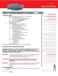
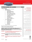
hypercharger for t win cam 9752
Chrome Body with Candy blue Butterflies and Trap Door
Fi t s : ’ 9 9 – u p T wi n C am with C V Car b uretor and ’06–u p T w in C am with Del phi EFI.
Part#
408332
909975
9920
909999
Included
1
1
2
1
1
1
1
4
1
1
1
2
1
1
3
1
2
4
1
1
Chrome Hypercharger Assembly
Trap Door – Candy Blue
Butterflies – Candy Blue
Support Bracket
Breather Hardware Kit, including:
1-1/4” Breather Bolts (pr)
Breather Hoses (pr)
Shim Washers, 0.030 thickness
Twin Cam Breather Kit, Including:
Breather Adapter/Spacer
90° Barbed Fitting 1/8 NPT
180° Barbed Fitting 1/4-28
16” Vacuum Hose
Barbed “T” Fitting
1/4-20 x 1-1/2” SHCS, Patched
Gasket with Adhesive
Gasket without Adhesive
4” Nylon Cable Ties
Delphi Vacuum Adapter
Installation Instructions
Please read and understand entire instructions before starting installation.
Thank you for choosing Kuryakyn!
WARNING! The possibility of contact between the Hypercharger and
the fuel tank exists on ’06-later Dyna models. The following
steps MUST be taken during installation to ensure adequate
clearance:
• Apply downward pressure to the right (front cylinder) side of the support
bracket as the breather bolts are tightened. At the same time, you must ensure
that the three 1/4”-20 threaded holes in the throttle body line up with the
corresponding holes in the support bracket.
• Rotate the Hypercharger assembly clockwise and down as the three 1/4”-20
x 1-1/2” socket head cap screws are tightened to provide maximum fuel tank
clearance.
• Immediately after installation, verify there is adequate clearance between the
Hypercharger assembly and the tank with motorcycle at idle and under load.
NOTE KURYAKYN WILL NOT BE HELD RESPONSIBLE FOR ANY DAMAGE
CAUSED BY FAILURE TO ENSURE PROPER CLEARANCE.
CAUTION! The installation of any high performance air cleaner and/or exhaust system
can cause a “lean” fuel/air mixture. A “lean” fuel/air mixture can cause engine
overheating resulting in severe engine damage. Kuryakyn recommends having
the motorcycle tuned by a competent technician.
-cont.-
9752-15HD-0407
CUSTOMER SERVICE
877.370.3604 (toll free)
INSTALLATION QUESTIONS
[email protected]
or call 715.247.2983
LIMITED WARRANTY
Küryakyn warrants that any Küryakyn products sold
hereunder, shall be free of defects in materials and
workmanship for a period of one (1) year from the
date of purchase by the consumer excepting the following provisions:
• Küryakyn shall have no obligation in the event
the customer is unable to provide a receipt showing
the date the customer purchased the product(s).
• The product must be properly installed,
maintained and operated under normal conditions.
• Küryakyn makes no warranty, expressed or
implied, with respect to any gold plated products.
• Küryakyn shall not be liable for any consequential
and incidental damages, including labor and
paint, resulting from failure of a Küryakyn product,
failure to deliver, delay in delivery, delivery in nonconforming condition, or for any breech of contract or
duty between Küryakyn and a customer.
• Küryakyn products are often intended for use
in specific applications. Küryakyn makes no
warranty if a Küryakyn product is used in
applications other than intended.
• Küryakyn electrical products are warranted for one
(1) year from the date of purchase by the consumer.
Components of Küryakyn products containing L.E.D.s
will be warranted for defects in materials and
workmanship for 3 years from the date of purchase.
• Küryakyn makes no warranty of any kind in regard
to other manufacturer’s products distributed by
Küryakyn. Küryakyn will pass on all warranties made
by the manufacturer and where possible, will expedite
the claim on behalf of the customer,
but ultimately, responsibility for disposition of the
warranty claim lies with the manufacturer.
ABOUT OUR CATALOG
You’ll find all our innovations for H-D, GL and
Metric Cruisers in our annual catalogs. Order online
today–select the ”CATALOGS” icon. Each Küryakyn
product comes with a Proof-of-Purchase good for a
complimentary catalog. Details in packaging.
Be sure to ask your local dealer about other
Küryakyn products, the motorcycle parts and accessories designed for riders by riders.
©2005 Küryakyn USA All Rights reserved.
Attention!A factory service manual is necessary for performing this installation. Do not attempt to
perform this installation if you are not confident in your ability to complete all steps in the
procedure; consult a trained technician.
Note
It is the installers’ responsibility to make sure all fasteners (including pre-
Note
Some of our high performance air cleaners extend beyond the stock/OEM unit
PIC.1
assembled) are tightened before operation of motorcycle. Küryakyn will not
warranty components that are lost due to improper installation. Periodic
maintenance may be required.
to achieve smoother air flow and better performance. Riding position may be
affected.
For ’06-up Fuel Injected Models Only
Note
®
from the motorcycle for clarity. You DO NOT
have to remove the throttle body to perform
this installation.
Left side
1-1/2”
bolt
Procedure
nut
STEP 2 Remove the air cleaner; refer to your factory
service manual for specific instructions.
STEP 3 Remove the throttle and idle cables (and
cruise control cable, if fitted); refer to your factory service
manual for specific instructions.
2” bolt
STEP 7 Assemble the vacuum adapter.
Install the rubber manifold air pressure
seal onto the adapter body. See PIC.3.
Install the vacuum adapter on the MAP
sensor. Be sure the orientation of the hose
barb is correct. See PIC.4 next page.
-cont.-
nut
stock location
1-1/2”
b o lt
sta bilizer link
frame
1 / 16 ”
wa s h e r
motor
mount
nut
nut
pressure) sensor and the IAC (idle air controller) unit.
PIC.3
remove the MAP sensor. See PIC.2.
frame
s pacer
new location
STEP 5 Remove the two wiring harnesses going to the MAP (manifold air
STEP 6 Remove the IAC bracket;
2 ” bo lt
spac e r
motor
mount
factory service manual for specific instructions.
is not adequate clearance for the MAP sensor after
the vacuum adapter is installed. You must remove and
reposition the stabilizer link hardware to allow sufficient
clearance for the MAP sensor. Locate the stabilizer link
between the frame and the motor mount. See PIC.1.
Remove the stock hardware and re-install in the new
location following the diagram in FIG.1.
right side
sta bil izer link
1/16”
washer
STEP 1 Remove the seat and fuel tank; refer to your
STEP 4 For FXD models only: On Dyna models, there
sta bil izer
l inkage
fig.1
The following photos show the throttle body removed
self-ta pping
fastener
PIC.2
MAP sensor
iac unit
iac bracket
hold-down
pl ate
vacuum
adapter
ca ble
connec t ions
Page
man ifold air
pressure seal
2
hypercharger
INSTALLATION
STEP 8 Install the IAC bracket on the throttle body. DO NOT tighten the fasteners yet. Be sure the
®
peg on the bottom of the MAP sensor fits into the alignment hole on the throttle body. See PIC.5.
PIC.4
STEP 9 Insert the MAP sensor assembly into the throttle body. The vacuum
adapter body fits under the tab on the IAC bracket. Be sure the orientation of
the hose fitting is correct. See PIC.6. Tighten the fasteners on the IAC bracket.
vacuum
ada pter
MAP s e n s o r
STEP 10 Connect one end of the vacuum hose included with the Hypercharger
to the hose fitting on the vacuum adapter.
STEP 11 Connect the wiring harnesses to the MAP sensor and the IAC unit.
STEP 12 Reconnect the throttle and idle cables (and cruise control, if fitted).
Install the air cleaner, fuel tank and seat; refer to your factory service manual for
specific instructions.
hold-down
pl ate
STEP 13 Position the chrome support bracket over the mouth of the
PIC.5
throttle body and fasten loosely to each head with the supplied breather
bolts.
peg
Caution! Be sure the support bracket is fully seated against
the heads and that there is no gap, use the
supplied shims as needed. A gap will result in a
broken support bracket.
STEP 14 Slide an intake gasket between the support bracket and the
throttle body mouth; be sure all the holes are aligned. Tighten the breather
bolts.
STEP 15 Trim 1/4” from each end of ONE of the supplied breather hoses.
Install this hose between the front head and the 90° fitting on the breather
adapter.
al ignment
hole
PIC.6
STEP 16Install the remaining breather hose between the rear breather bolt and
ta b o n iac
b r ac k e t
the straight barbed fitting on the breather adapter. Secure the ends of the two
hoses with the supplied cable ties; trim the cable tie ends. See PIC.7.
STEP 17 Remove the paper backing from the self-adhesive intake gasket and
apply the gasket between the Hypercharger and the breather adapter. Be sure to
align the holes.
STEP 18 Use an 1/8” Allen wrench to remove the trap door from the
Hypercharger.
STEP 19 Install the three supplied 1/4” SHCS into the Hypercharger mounting
holes.
STEP 20While holding the gaskets in place
between the breather adapter, support bracket, and
air cleaner, secure the assembly to the throttle body.
DO NOT over tighten the fasteners; hand tight plus
1/4 turn with a wrench is sufficient torque to secure
the fasteners.
STEP 21 Replace the trap door on the
Hypercharger. Connect the vacuum line to the air jet
on the bottom of the Hypercharger vacuum pod.
-cont.-
PIC.7
vacuum
ada pter
Page
3
hypercharger
INSTALLATION
®
For Carbureted Models Only — Procedure
STEP 1 Remove the stock air cleaner assembly.
STEP 2 Use needlenose pliers to remove the vacuum hose from the vacuum tap on
PIC.8
the rear of the carburetor. See PIC.8. This step may require the removal of the carburetor
from the intake manifold; consult your factory service manual.
STEP 3 Cut a 1-1/2” length of vacuum hose from the vacuum hose provided. Connect
the vacuum lines to the barbed “T” fitting as shown in PIC.9. Reconnect the vacuum line
assembly to the carburetor as shown in PIC.10.
STEP 4 If the carburetor was removed in STEP 2, reinstall it now. Be sure the
carburetor is fully seated in the manifold; wetting the rubber seal may make this easier.
STEP 5 Position the chrome twin cam mounting bracket over the mouth of the
carburetor and fasten loosely to each head with the stock breather bolts.
PIC.9
Caution! Be sure the support bracket is fully seated against the heads
and that there is no gap, use shims as needed. A gap will
result in a broken twin cam support bracket.
STEP 6 Slide an intake gasket between the support bracket and the carburetor mouth;
be sure all the holes are aligned. Rotate the carburetor in either direction to align the
holes. Tighten the breather bolts.
STEP 7 Trim 1/4” from each end of ONE of the supplied breather hoses. Install this
hose between the front head and the 90° fitting on the breather adapter.
PIC.10
STEP 8 Install the remaining breather hose between the rear breather bolt and the
straight barbed fitting on the breather adapter. Secure the ends of the two hoses with the
supplied cable ties; trim the cable tie ends. See PIC.11.
STEP 9 Remove the paper backing from the self-adhesive intake gasket and apply the
gasket between the Hypercharger and the breather adapter. Be sure to align the holes.
STEP 10 Use an 1/8” Allen wrench to remove the trap door from the Hypercharger.
STEP 11 Install the three supplied 1/4” SHCS into the Hypercharger mounting holes;
note that the hole in the 10 o’clock position is the float bowl vent—do not use this hole.
PIC.11
STEP 12 While holding the gasket in place between the breather adapter and support
bracket; secure the assembly to the carburetor. Do NOT over tighten the fasteners; the
aluminum will strip easily.
STEP 13 Replace the trap door on the Hypercharger. Connect the vacuum line to the air
jet on the bottom of the Hypercharger vacuum pod.
STEP 14 Check for proper throttle operation.
Ride On!
Page
4
hypercharger
INSTALLATION