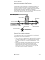
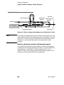
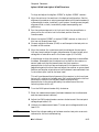
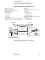
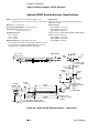
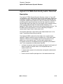
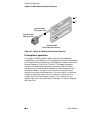
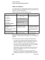
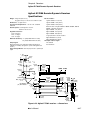
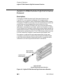
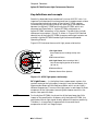
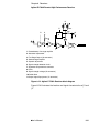
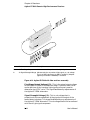
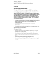
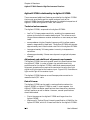
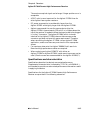
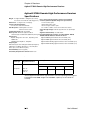
1
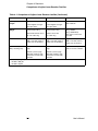
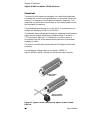
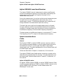
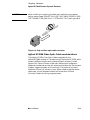
8
Receivers
Chapter 8 Receivers
General
General
One receiver is required for each measurement or wavelength tracker
axis.
The receiver converts the Doppler component of the laser beam from an
interferometer or wavelength tracker into an electrical signal for the
measurement electronics.
This chapter describes the following receivers:
•
Agilent 10780C Receiver,
•
Agilent 10780F Remote Receiver,
•
Agilent E1708A Remote Dynamic Receiver, and
•
Agilent E1709A Remote High-Performance Receiver
The Agilent 5519A and 5519B laser heads, which are a component of
the Agilent 5529A/55292A Dynamic Calibrator system, has a built-in
receiver. This chapter includes a brief description of that receiver.
However, the installation and alignment of that receiver occurs as part
of the Agilent 5519A/B Laser Head installation and alignment
procedures, given in the Agilent 5519A Laser Head Service Manual.
Receiver specifications are given later in this chapter.
Comparison of Agilent Laser Receiver
Families
Table 8-1 summarizes the features, characteristics, and specifications
the Agilent 10780C/F, Agilent E1708A, and Agilent E1709A receivers.
The Agilent E1708A receiver is functionally similar to the
Agilent 10780F receiver. However, the E1708A is not a direct
replacement for 10780F. Comparisons of the two laser receiver families
are provided in Table 8-1.
8-2
User’s Manual
Chapter 8 Receivers
Comparison of Agilent Laser Receiver Families
.
Table 8-1. Comparison of Agilent Laser Receiver families
Characteristic
E1709A Receiver
E1708A Receiver
10780C, 10780F Receivers
Dynamic Range
25:1 to 6:1, depending on
the AC/DC ratio
10:1
Not specified
Sensitivity
.20 -.80 µW (depending on
the AC/DC ratio), with 2
meter plastic cable
2.2 µW (E1708A with
2-meter fiber optic cable)
1.5 µW (10780C)
Alignment Tolerance
For plastic fiber optic cable
(Option 010)
Roll: ±3°
Pitch: ±1°
Yaw: ±1°
Agilent remote sensor is
self-aligning with some
interferometers.
5 µW (E1708A with
10-meter fiber optic cable)
For plastic fiber optic cable
Roll: ±3°
Pitch: ±1°
Yaw: ±1°
Agilent remote sensor is
self-aligning with some
interferometers.
2.2 µW (10780F with
2-meter fiber optic cable)
5 µW (10780F with 10-meter
fiber optic cable)
Roll: ±3°
Pitch: ±1°
Yaw: ±1°
10780F is self-aligning with
some interferometers.
Output Signal
Frequency
(Differential square
wave at Doppler-shifted
frequency)
100 kHz to 15.5 MHz
(slew rates to 1 m/s with
plane mirror optics)
100 kHz to 7.2 MHz
(slew rate to 500 mm/s with
plane mirror optics)
100 kHz to 7.2 MHz
Fixed Data Delay
(typical)*
33.2 ns (typical) 0.01 ns/°C
86 ns
Not specified
Errors due to
frequency variations
at fixed temperature*
For 25:1 to 6:1 input
amplitude variations and
frequency range of 100 kHz
to 15.5 MHz
For 3:1 input
amplitude variations and
frequency range of 100 kHz
to 7.2 MHz
Not specified
< ±1.2 nm for linear optics
< ±0.6 nm for plane mirror
optics
< ±0.3 nm for high resolution
optics
< ±1.2 nm for linear optics
< ±0.6 nm for plane mirror
optics
< ±0.3 nm for high resolution
optics
Signal Strength
Monitor
0 to 10 volts output, proportional to optical input signal
power
0 to 8 volts output,
proportional to optical input
signal power
Range: 0 to 0.8 volts
Power Requirements
15 Vdc ±1V at less than
267 mA
15 Vdc ±1V at less than
250 mA
+15 Vdc at 136 mA
Heat Dissipation
0.0 W for remote sensor
4.0 W typical for receiver
0.0 W for remote sensor
0.0 W for remote sensor
3.8 W typical for receiver
2.0 W typical for receiver
0 to 40° C operating
0 to 40° C operating
0 to 40° C operating
Temperature Range
User’s Manual
8-3
Chapter 8 Receivers
Comparison of Agilent Laser Receiver Families
Table 8-1. Comparison of Agilent Laser Receiver families (Continued)
Characteristic
E1709A Receiver
E1708A Receiver
10780C, 10780F Receivers
Fiber-Optic Cable
Length
Option 010: 2m (plastic)
2 m standard (plastic)
2 m standard
Contact Agilent for longer
fiber optic cables.
Contact Agilent for longer
fiber optic cables.
Receiver body:190 g
Receiver body:170 g,
Option 010: Remote sensor
with 2 m cable: 26 g
Remote sensor with
2 m cable: 26 g
Height: 78.1 mm (3.075 in)
Width: 115.6 mm (4.552 in
Depth: 19.8 mm (0.780 in)
Height: 78.1 mm (3.075 in)
Width: 115.6 mm (4.552 in
Depth: 19.8 mm (0.780 in)
Height: 38.1 mm (1.50 in)
4 holes at corners of a rectangle
4 holes at corners of a rectangle
2 holes 107.8 mm (4.25 in)
apart on receiver centerline
40.0 mm (1.575 in) high
108.0 mm (4.250 in) wide,
centered on receiver body
centerline
40.0 mm (1.575 in) high
108.0 mm (4.250 in) wide,
centered on receiver body
centerline
Weight
Dimensions
Dimensions (receiver
body, mounting area)
10 m maximum
136 g, 10780C
126 g, 10780F body
26 g, remote sensor with
2 m cable
Width: 114.8 mm (4.52 in)
Depth: 19.8 mm (0.78 in)
* For ac input signal power:
E1708A: <200 µW
E1709A: <50 µW
8-4
User’s Manual
Chapter 8 Receivers
Agilent 10780C and Agilent 10780F Receivers
Agilent 10780C and Agilent 10780F
Receivers
Description
General
The Agilent 10780C Receiver or Agilent 10780F Remote Receiver
converts the Doppler-shifted laser light from an interferometer or the
wavelength tracker into electrical signals that can be processed by the
rest of the laser system.
Lens and polarizer
Light enters either receiver through a lens and polarizer.
The Agilent 10780C lens and polarizer are built into the same
assembly that houses the receiver electronics. Agilent 10780C
Receiver’s lens focuses the laser light onto a silicon PIN photodiode.
Between the lens and the diode is a small piece of polarizing material
oriented at 45° to the horizontal and vertical axes of the receiver.
The Agilent 10780 Remote Receiver’s lens and polarizer are contained
in a small assembly that is connected to the electronics housing by a
fiber optic cable. The fiber optic cable allows the receiver module to be
mounted away from the measurement area, removing a source of heat.
The interference signal between the f1 and f2 polarizations is sent
through the fiber optic cable to the electronics housing. The
Agilent 10780F receiver’s fiber optic sensor head may be mounted
directly to certain interferometers (Agilent 10719A, Agilent 10721A,
Agilent 10735A, Agilent 10736A).
Alignment pins are provided for easy installation and alignment. This
eliminates the need for any other user-supplied mount for the sensor
head.
When the receiver input is oriented properly, that is, with its vertical
axis parallel or perpendicular to the axes of the laser head, the
polarizer passes one-half the incident power from each of the two
incoming orthogonally polarized components of the received laser
beam.
User’s Manual
8-5
Chapter 8 Receivers
Agilent 10780C and Agilent 10780F Receivers
Photodiode
The output from the polarizer assembly is an amplitude-modulated
sine wave that is sent to a photodiode chip in the receiver’s electronic
housing. The frequency is the Doppler-shifted split frequency. The
amplitude is proportional to the product of the incident powers of the
two orthogonal components.
The photodiode generates an ac current, which is converted to an ac
voltage at a frequency of 100 kHz to 6.0 MHz.
The detected signal voltage goes through an impedance transformation
stage, two gain stages, and a level translation stage. The result, a
TTL-level signal, goes to a TTL differential line driver, which is
ac-coupled to the rest of the measurement electronics by a shielded
twisted-pair cable.
The output is a differential square wave at the Doppler-shifted split
frequency.
An available dc voltage output on the Agilent 10780C or
Agilent 10780F receiver indicates incoming laser beam intensity.
FR
: OUSING
ION R H NT
UT IVE OU
CARECEOM M
LA
SO
Y I Y.
LL NL
ICA S O
ON EW
TR CR
EC S
EL ON
BE NYL
E
LD US
OU E SHTUR
INGFIX
de
in
U.
S.
A.
C
FR
TE
D
Agilent 10780C
Receiver
: OUSING
ION R H NT
UT IVE OU
CARECEOM M
0
7 8R
1RE0CEIVE
Ma
Ma
de
in
U.
S.
A.
D
TE
LA
SO
Y I Y.
LL NL
ICA S O
ON EW
TR CR
EC S
EL ON
BE NYL
E
LD US
OU E SHTUR
INGFIX
R
0 FEIVE
7 8REC
1RE0MOTE
Agilent 10780F
Remote Receiver
Figure 8-1. Agilent 10780C Receiver and Agilent 10780F Remote
Receiver
8-6
User’s Manual
Chapter 8 Receivers
Agilent 10780C and Agilent 10780F Receivers
Agilent 5519A/B Laser Head Receiver
The Agilent 5519A/B internal measurement receiver amplifies and
converts the difference frequency of the laser beam (returned by the
system optics) to TTL levels and supplies the signal to the
measurement electronics.
During the measurement, the vertical and horizontal components pass
through the turret and measurement optics and return to the
measurement receiver. The difference between their frequencies will
change whenever the measurement optics are moving.
The laser light returning from the measurement optics is directed
through a polarizer and onto a photodiode. Because of the polarizer
orientation, the beam power past the polarizer varies sinusoidally at
the difference frequency of the two laser frequency components.
The beam power at the difference frequency is converted to TTL levels.
The frequency of the TTL output is the measurement frequency.
Special considerations
Cables
General
Each Agilent 10780C or Agilent 10780F receiver requires a cable to
carry signals and power between it and the measurement electronics
axis board with which it is to be used. One cable is required per
measurement axis. The cable used depends on the axis board used, and
the cable length required.
Cables are described in Chapter 9, “Accessories,” of this manual.
The Agilent 5519A/B Laser Head receiver connection is made via the
cable that also provides power for the laser. The cable depends on the
axis board used. Cables are described in Chapter 9, “Accessories,” of
this manual.
Agilent 10790A/B/C cables
An Agilent 10790A, Agilent 10790B, or Agilent 10790C Receiver Cable
is used to connect the Agilent 10780C or Agilent 10780F receiver to the
Agilent 10895A VME Axis Board, for both measurement and
Wavelength Tracker axes.
User’s Manual
8-7
Chapter 8 Receivers
Agilent 10780C and Agilent 10780F Receivers
Agilent 10880A/B/C cables
An Agilent 10880A, Agilent 10880B, or Agilent 10880C Receiver Cable
is used to connect an Agilent 10780C or Agilent 10780F receiver to an
Agilent 10885A PC Axis Board, Agilent 10889B PC Servo Axis Board,
Agilent 10896B VME Laser Compensation Board, Agilent 10897B
VME High Resolution Laser Axis Board, Agilent 10898A VME High
Resolution Dual Laser Axis Board, or Agilent N1231A PCI Three-Axis
Board, for both measurement and Wavelength Tracker axes.
Effects of motion and orientation
Motion of the receiver or laser head along the beam path (X) has no
effect on the measurement, since both f1 and f2 would exhibit Doppler
shift.
Small motions of the laser head, receiver, interferometer, or
retroreflector in a direction perpendicular to the beam path (Y or Z)
have no effect on the measurement. The only restriction is that
sufficient light returns to the receiver.
Although the Laser Head or the Receiver may be rotated in 90°
increments about the beam axis (roll), other roll deviations from the
four optimum positions degrade the measurement signal. If either the
Laser Head or Receiver is rotated 45° about the beam axis, all position
information will be lost because the receiver will not be able to
distinguish between the two frequencies.
Angular motion of the receiver about the Y axis, the Z axis, or both, has
no effect on the measurement, within certain alignment limits.
8-8
User’s Manual
Chapter 8 Receivers
Agilent 10780C and Agilent 10780F Receivers
Mounting
Offset aperture
Offset aperture allows flexibility in mounting the Agilent 10780C or
Agilent 10780F receiver (that is, the bulk of the receiver or sensor head
can be mounted above, below, right, or left of the incoming laser beam).
Agilent 10780F Remote Receiver sensor head
The Agilent 10780F receiver’s fiber optic sensor head may be mounted
directly to certain interferometers (Agilent 10719A, Agilent 10721A,
Agilent 10735A, Agilent 10736A). Alignment pins are provided for easy
installation and alignment. This eliminates the need for any other
user-supplied mount for the sensor head.
Installation
When installing the receiver, keep the following points in mind:
CAUTION
•
At a 45° position (roll), the signal will go to zero.
•
Plastic mounting hardware electrically isolates the Agilent 10780C
or Agilent 10780F receiver from the machine and reduces problems
with heat conduction.
•
The receiver typically dissipates 2.0 watts, with a maximum
dissipation of 2.7 watts. Plastic pads keep an air gap around the
receiver and act as thermal and electrical isolators.
Use Nylon screws only (Agilent 2360-0369). The receiver housing must
be electrically isolated from the mounting fixture.
•
The remote sensor in the Agilent 10780F Remote Receiver does not
dissipate any power. The remote sensor does not require a nylon
screw.
•
Allow a 5 cm space at the rear of each receiver housing for each
cable connection.
•
Maintain a bend radius of at least 35 mm (1.4 inches) to prevent
signal attenuation in the Agilent 10780F receiver’s fiber optic
cable.
Cable connection
Agilent 10790A/B/C Receiver Cable
This cable’s connectors are identical on either end as shown in
Figure 9-6. The connectors on the cable and on the receiver and
Agilent 10895A axis board are “keyed” to go together only one way. The
connectors on the cable each have a locking ring, which takes a
1/4-turn clockwise to secure the cable to its mating connector.
User’s Manual
8-9
Chapter 8 Receivers
Agilent 10780C and Agilent 10780F Receivers
CAUTION
Each connector on an Agilent 10790A, Agilent 10790B, or Agilent
10790C cable has both a male and female half. Before making a
connection, be sure the male half of the cable connector is properly
aligned with the female half of the mating connector. Failure to align
the pins prior to mating the connectors may result in damaged pins.
Agilent 10880A/B/C Receiver Cable
The connectors at each end are different as shown in Figure 9-7.
One connector is a bayonet connector that inserts into the
Agilent 10885A, 10889B, 10896B, 10897B, 10898A, or N1231A axis
board. The connectors lock together. To unlock the connectors, slide the
cable connector sleeve away from the Agilent axis board’s panel until
the connectors separate.
CAUTION
Any attempt to twist the cable connector when it is connected to the
Agilent 10885A panel connector may cause damage.
The other connector fits the connector on the receiver; this connector is
“keyed” to go together only one way. This connector has a locking ring,
which takes a 1/4-turn clockwise to secure the cable to its mating
connector on the receiver.
Fasteners
The supplied nylon screws must be used to assure that the receiver
housing is electrically isolated from the mounting fixture.
Clearance for laser beam
Figure 8-2 shows: 1) the clearance requirement for the laser beam
passing the receiver or sensor head on its way to the interferometer or
wavelength tracker, and 2) how the receiver alignment target can be
used to be sure the receiver is positioned correctly with respect to this
beam. Laser beam clearance is also shown in the receiver specification
drawings at the end of this chapter.
8-10
User’s Manual
Chapter 8 Receivers
Agilent 10780C and Agilent 10780F Receivers
RECEIVER BEAM CLEARANCES AND ALIGNMENT TARGETS
Laser Beam From Laser Head
(Small Aperture On Laser Head)
Agilent 10780C
Receiver
Small Aperture
Laser Beam From
Interferometer
Alignment Target
Small Laser Beam
Going To Interferometer
m
7m
12. (0.5)
Agilent 10780F
Remote Receiver
Laser Beam From Laser Head
(Small Aperture On Laser Head)
Small Aperture
Laser Beam From
Interferometer
Alignment Target
Small Laser Beam
Going To Interferometer
m
7m
12. (0.5)
Figure 8-2. Agilent 10780C and Agilent 10780F Receiver beam clearances and alignment
targets
User’s Manual
8-11
Chapter 8 Receivers
Agilent 10780C and Agilent 10780F Receivers
Alignment
General
Each Agilent 10780C or Agilent 10780F Receiver in the measurement
system requires an alignment relative to its input beam to maximize
its measurement signal strength.
This alignment is typically done by positioning the receiver so the two
polarization vectors from the laser head are parallel or perpendicular
to the plane defined by the centerlines of the two mounting holes
(within ± 3°).
Also, the beams should be centered on the receiver's input lens.
Alignment target
The Agilent 10780C or Agilent 10780F receiver is supplied with a
snap-on beam target to ease coarse alignment. The alignment targets
are shown in Figure 9-14 of Chapter 9, “Accessories,” in this manual.
The alignment target attaches at the receiver lens and helps align the
receiver to the center of the incident beam. It is also used to adjust the
spacing between the beam going to the interferometer and the return
beam incident on the receiver.
The Agilent Part Number for the standard Alignment Target for the
Agilent 10780C Receiver is 10780-40003.
The alignment target for use with an Agilent 10780F Remote Receiver
having a 9 mm lens is Agilent Part Number 10780-40009.
Principle
The receiver is aligned by moving it and rotating it relative to the beam
axis.
Receiver alignment is performed during the optical system alignment.
The receiver is moved to center the incident beam on its input lens.
The receiver photodetector only measures the overlapping portion of
the laser beams.
For maximum signal strength, the interferometer and retroreflector
are aligned so the reference beam from the interferometer and the
measurement beam from the retroreflector exactly overlap upon
recombination. These recombined laser beams then enter the receiver
at the center of its input lens. From Figure 8-3, it is clear that if the
recombined laser beams entering the receiver are not centered on the
photodetector, measurement signal loss will occur. If the
8-12
User’s Manual
Chapter 8 Receivers
Agilent 10780C and Agilent 10780F Receivers
interferometer or the retroreflector is misaligned (Figure 8-3), the
reference and measurement beams no longer completely overlap,
resulting in signal loss. Typically, a lateral offset of 1/4 of the beam
diameter between the beams is allowable for an adequate
measurement signal. However, you must make every effort to optimize
the laser beam overlap for maximum performance.
Optics Misalignment
Reference Beam
Retroreflector
Laser Beam
Receiver
See
View A–A
Reference Beam
Measurement Beam
Measurement Beam
Receiver Detects Only
Overlapped Portion
View A–A
Figure 8-3. Effect of optics misalignment
If the measurement beam is not aligned parallel to the direction of
retroreflector travel, there are two effects.
•
First, a cosine error is generated of a magnitude directly related to
the angle of misalignment. For a complete description of cosine
error, refer to Chapter 15, “Accuracy and Repeatability,” in this
manual.
•
Second, when movement occurs between the optics, the angular
misalignment also causes a lateral displacement of the
measurement beam with respect to the reference beam at
recombination, resulting in additional signal loss. Figure 8-4
illustrates the result of angular misalignment.
User’s Manual
8-13
Chapter 8 Receivers
Agilent 10780C and Agilent 10780F Receivers
Angular Misalignment
Laser Axis
Reference Beam
Retroreflector
Position 1
Retroreflector
Position 2
Laser Beam
Receiver
Interferometer
Measurement Beam
Travel Axis
Figure 8-4. Effects of Angular Misalignment to the Direction of Travel
NOTE
The presence of measurement signal through the total length of travel
does not guarantee that the measurement axis is aligned for minimum
cosine error. Also, any angular misalignment of the laser beam to the
direction of travel causes a decrease in the measurement signal
strength.
Receiver alignment and gain adjustment procedure
The procedures presented here are common to most of the alignment
procedures or techniques presented in Chapter 4, “System Installation
and Alignment,” and Chapter 7, “Measurement Optics,” of this
manual. Usually, aligning the receiver and adjusting its gain will be
done after all other optics alignment has been done.
8-14
User’s Manual
Chapter 8 Receivers
Agilent 10780C and Agilent 10780F Receivers
To align and adjust the Agilent 10780C or Agilent 10780F receiver:
1 Align the optics on the machine in the desired configuration. See the
alignment procedures or techniques applicable to the interferometer(s)
or wavelength tracker installed in your system. Use alignment targets,
alignment aids, or both, to establish proper beam spacing and
positioning.
2 Run the system stage out to its limit such that the retroreflector or
plane mirror for one axis is at its furthest position from the
interferometer.
3 Mount the Agilent 10780C or Agilent 10780F receiver on that axis, if
this has not already been done.
4 Connect a digital voltmeter (DVM) or oscilloscope to the test point on
the back of the receiver.
5 Align the receiver for a maximum positive voltage at the test point.
You may have to adjust the gain potentiometer to keep the test point
voltage out of saturation and in the linear region (0.1 to 0.8V).
NOTE
A simple way to align the receiver is to use a gage block to autoreflect
the beam. Remember that the objective is to position the receiver or
sensor head such that the beam enters the input aperture
perpendicular to its front face and centered in the aperture. Hold the
gage block against the front face and adjust the receiver or sensor head
position and angular orientation so that the beam is autoreflected, that
is, coincident upon itself at the laser head.
This will provide excellent alignment of the receiver in pitch and yaw,
but not roll, relative to the beam axis. Roll must be aligned so the two
polarization vectors from the laser head are parallel to or
perpendicular to the plane defined by the centerlines of the two
mounting holes, within ±3°.
6 Turn the GAIN potentiometer fully clockwise.
7 Block the measurement beam (the beam between the interferometer
and the measurement reflector).
8 Adjust the GAIN potentiometer counter-clockwise until the test point
voltage drops below 0.1V.
9 Unblock the measurement beam. The test point voltage should be at
least 0.7V.
NOTE
Record the voltage reading at the beam monitor test point as an axis
reference for future troubleshooting.
User’s Manual
8-15
Chapter 8 Receivers
Agilent 10780C and Agilent 10780F Receivers
Operation
The Agilent 10780C Receiver or Agilent 10780F Remote Receiver
normally receives its operating power from the measurement
electronics to which it is connected. When the measurement electronics
are turned on, the receiver will turn on.
An LED on the Agilent 10780C or Agilent 10780F receiver signals
beam capture.
An available dc voltage output on the Agilent 10780C or
Agilent 10780F receiver indicates incoming laser beam intensity.
Specifications and characteristics
Specifications describe the device’s warranted performance.
Supplemental characteristics (indicated by TYPICAL or NOMINAL)
are intended to provide non-warranted performance information useful
in applying the device.
Specifications for the Agilent 10780C Receiver and Agilent 10780F
Remote Receiver are given below.
Specifications for the Agilent 5519A/B Laser Head’s internal receiver
are given in Chapter 5, “Laser Heads,” of this manual.
Sensitivity
The maximum sensitivity of the Agilent 10780C is 1.5 µW (factory-set
at 5 µW) and can be adjusted via an externally accessible
potentiometer. The adjustment procedure is given earlier in this
chapter.
Maximum sensitivity of the Agilent 10780F Remote Receiver is 2.2 µW
with its standard 2 m cable (a 10 m cable reduces the sensitivity to
5.0 µW).
The difference between the Agilent 10780C and the discontinued
Agilent 10780A and Agilent 10780B models is the increased bandwidth
and sensitivity of the Agilent 10780C to laser light.
8-16
User’s Manual
Chapter 8 Receivers
Agilent 10780C and Agilent 10780F Receivers
Agilent 10780C Receiver Specifications
Weight: 136 grams (4.8 ounces)
Output Signal:
Dimensions: see figure below
Differential square wave at Doppler-shifted split frequency
(100 kHz to 7.2 MHz)
Typical Power Requirements: +15 volts at 136 mA
Heat Dissipation: 2.0 W typical
Electrical Cables:
Alignment Tolerances:
Agilent 10790A: 5 m (15.2 ft)
Roll: ±3 degrees
Agilent 10790B: 10 m (30.5 ft)
Pitch: ±1 degree
Agilent 10790C: 20m (61 ft)
Yaw: ±1 degree
Electrical cables for Agilent 10885A, 10889B, 10896B, 10897B,
10898A, or N1231A axis board:
Maximum Sensitivity: 1.5 µW
Factory adjusted to 5.0 µW; can be adjusted to maximum sensitivity
using procedures in the Agilent 10780C/F Operating and Service
Manual.
Agilent 10880A, 5 m (15.2 ft)
Agilent 10880B, 10 m (30.5 ft)
Agilent 10880C, 20m (61 ft)
Beam Diameter
6 mm (0.24)
Beam Spacing
12.7 mm (0.50)
Insulating
Mounting Pads
107.8 mm
(4.25)
38.1 mm
(1.50)
10780C RECEIVER
Photodetector
Agilent Techn ologies
7.6 mm
(0.30)
L
11.4 mm
(0.45)
50 mm
(2.0)
2.3 mm
(0.09) T yp
114.8 mm
(4.52)
15.2 mm
(0.60)
Clearance hole
for M3(6-32) Screw
2 Places
9.9 mm
(0.39)
Use Only Nylon Mounting Screw
HP 2360-0369 to A void Ground Loop.
Figure 8-5. Agilent 10780C Receiver — dimensions
User’s Manual
8-17
Chapter 8 Receivers
Agilent 10780C and Agilent 10780F Receivers
Agilent 10780F Remote Receiver Specifications
Weight: 126 grams (4.5 ounces) for Agilent 10780F receiver
Output Signal:
26 grams (0.9 ounce) for remote sensor with a 2 meter cable
Dimensions: see figure below
Differential square wave at Doppler-shifted split frequency
(100 kHz to 7.2 MHz)
Electrical Cables:
Typical Power Requirements: +15 volts at 136 mA
Agilent 10790A: 5 m (15.2 ft)
Heat Dissipation: 2.0 W typical for receiver
Agilent 10790B: 10 m (30.5 ft)
Agilent 10790C: 20m (61 ft)
0 W for remote sensor
Electrical cables for Agilent 10885A, 10889B, 10896B, 10897B,
10898A, or N1231A axis board:
Alignment Tolerances:
Roll: ±3 degrees
Agilent 10880A, 5 m (15.2 ft)
Pitch: ±1 degree
Yaw: ±1 degree
Agilent 10880B, 10 m (30.5 ft)
Maximum Sensitivity: 2.2 µW (with 2-meter cable)
Agilent 10880C, 20m (61 ft)
Factory adjusted to 5.0 µW; can be adjusted to maximum sensitivity
using procedures in the Agilent 10780C/F Operating and Service
Manual. (Becomes 5.0 *W with a 10-meter fiber cable.)
Beam Spacing
12.7 mm (0.50)
Beam Diameter
6 mm (0.24)
7.6 mm
(0.30)
7.6 mm
(0.30)
9.9 mm
(0.39)
Clearance Hole
for 4-40 Screw
23.8 mm
(0.94)
19.1 mm
(0.75)
22.4 mm
(0.88)
3.5 mm
(0.14)
43.1 mm
(1.70)
Insulating
Mounting Pads
19.1 mm
(0.75)
15.5 mm
(0.61)
Clearance Hole
for M3 (6-32) Screw
2 Places
107.8 mm
(4.25)
R35 Minimum
(1.4) Bend Radius
38.1 mm
(1.50)
10780F RECEIVER
50 mm DM
(2.0)
114.8 mm
(4.52)
Agilent Technologies
7.6 mm
(0.30)
Clearance Hole
for M3 (6-32) Screw
2 Places
Use Only Nylon Mounting Screw
2.3 mm
(0.09) Typ HP 2360-0369 to Avoid Ground Loop.
Figure 8-6. Agilent 10780F Remote Receiver — dimensions
8-18
User’s Manual
Chapter 8 Receivers
Agilent E1708A Remote Dynamic Receiver
Agilent E1708A Remote Dynamic Receiver
Description
The Agilent E1708A Remote Dynamic Receiver, shown in Figure 8-7,
is intended for use in applications requiring sub-nanometer resolutions
of systems in motion. It extends the performance of systems that use
the Agilent 10897B High Resolution Laser Axis board for VMEbus by
providing performance consistent with the high resolution and low
variable data age of that board. As the Doppler shift caused by motion
of the system stage changes the measurement frequency, the
Agilent E1708A receiver ensures minimal phase processing errors. The
E1708A also provide immunity to errors induced by changes in
measurement signal (laser input) power level.
One receiver package is required for each measurement axis in the
Laser Transducer system being installed.
The Agilent E1708A receives the laser beam via a remote sensor
(Agilent E1706A) containing a lens and polarizer. A fiber-optic cable
(Agilent E1705A) carries the beam from the remote sensor to the
electronics in the receiver body. The fiber-optic cable length is
2.0 meters to allow for considerable mounting flexibility and ease of
use. This arrangement provides several benefits:
•
it allows the receiver body to be located well away from the point of
beam intercept so receiver heat is not dissipated near the
measurement area.
•
it makes easier access to the attenuator and squelch adjustments
possible, and
•
there is a much smaller package size in the measurement area.
User’s Manual
8-19
Chapter 8 Receivers
Agilent E1708A Remote Dynamic Receiver
J2
J1
er
Agilent E1705A
Fiber-Optic Cable
Agilent E1706A
Remote Sensor
S1
8
67
45
23
:G
S/N
eiv
ec
cR
mi
a
8A yn
70 e D
E1 mot
Re
Agilent E1708A
Remote Dynamic Receiver
Figure 8-7. Agilent E1708A Remote Dynamic Receiver
Principles of operation
The Agilent E1708A receiver’s body contains the photodetector,
preamplifiers, and a detector circuit designed to convert the laser beam
returning from an interferometer into a differential square wave at the
Doppler frequency (100 kHz to 7.2 MHz). The Doppler frequency
contains the measured displacement information (MEAS signal),
representing the relative motion between an interferometer and its
associated reflector. A squelch circuit allows the receiver’s signal
output to be turned off automatically if the input signal is not strong
enough. A secondary output from the receiver is a dc level that is
proportional to the input signal strength. LED indicators on the
receiver light when any input signal is detected. For a block diagram,
see Figure 8-8.
8-20
User’s Manual
Chapter 8 Receivers
Agilent E1708A Remote Dynamic Receiver
1 Photodetector, amplifier
2 Attenuator adjustment
3 Amplifier
4 LEDs
5 Squelch adjustment
6 Signal level detector circuit
7 Sinewave-to-squarewave converter
8 Signal strength connector (J2, see Figure 8-7)
9 Output signal/input power connector (J1, see Figure 8-7)
2
4
5
LED
8
1
6
3
7
9
4
LED
Figure 8-8. Agilent E1708A Receiver—block diagram
Installation
Refer to Agilent 10780C/F Receiver’s placement, mounting, installation
examples, and procedures for alignment to the laser beam. For more
specific mounting, installation, and alignment and adjustment
procedures, see the Agilent E1707A Dynamic Receiver and
Agilent E1708A Remote Dynamic Receiver Operating Manual.
User’s Manual
8-21
Chapter 8 Receivers
Agilent E1708A Remote Dynamic Receiver
Cables for electronics
The receiver cable to be used depends on the electronics (system) to be
used. Table 8-2 lists the available cables. Refer to the manual for your
system for more cabling information.
Table 8-2. Cables for use with an E1708A receiver
For use with these electronics
Use one of these Receiver Cables
Description
Agilent 10885A
PC Axis Board
5 meters: Agilent 10880A
These cables have a 4-pin BNC
connector on one end and a 4-pin
LEMO connector on the other.
Agilent 10887A
PC Calibrator Board
For cable lengths longer than 10
meters, use high-performance cables.
10 meters: Agilent 10880B
Agilent 10889B
PC Servo-Axis Board
Agilent 10896B
Laser Compensation Board for
VMEbus (with Agilent 10717A
Wavelength Tracker)
Agilent 10897B
High Resolution VMEbus Laser
Axis Board
Contact Agilent for information about
high-performance cables.
Use high-performance cables.
Contact Agilent for information.
Agilent 10898A VME High Resolution
Dual Laser Axis Board
Use high performance cables for
both the receiver and the laser
head.
Agilent N1231A PCI Three-Axis Board
Agilent 10895A
Laser Axis Board for VMEbus
These cables have a 4-pin BNC
connector on one end and a 4-pin
LEMO connector on the other.
5 meters: Agilent 10790A
10 meters: Agilent 10790B
These cables have a 4-pin BNC
connector on each end.
Each of these receivers has a polarizer as part of its input lens
assembly. The E1708A receiver’s lens assembly is in the remote sensor
assembly.
When mounting either receiver, remember the following points:
•
For maximum input signal strength, align the polarizer so its
polarization vectors are the same as those of the incoming laser
beam. At a 45-degree roll position, the signal goes to zero.
•
For either receiver body, power dissipation is typically 3.8 watts.
The receiver’s mounting feet keep an air gap around the receiver
and also act as thermal and electrical isolators.
•
Leave enough clearance for the signal cable that connects to the
receiver’s 4-pin signal and power connector. (See dimensional
drawing in Figure 8-10)
•
The receiver housing must be electrically isolated from the
equipment it is mounted on. The clearance holes in the receiver’s
insulating mounting feet let you use either 6-32 or M3.5 screws.
8-22
User’s Manual
Chapter 8 Receivers
Agilent E1708A Remote Dynamic Receiver
CAUTION
When installing or removing the fiber optic cable from the receiver
body or sensor head, DO NOT PULL ON THE CABLE PROPER, GRIP
THE CONNECTOR AND PULL IT STRAIGHT OUT (see Figure 8-9).
Figure 8-9. Grip and fiber-optic cable connector
Agilent E1705A Fiber-Optic Cable considerations
The Agilent E1705A Fiber-Optic Cable supplied with the
Agilent E1708A receiver is 2.0 meters long (The Agilent E1705A cable
comes in different lengths and is made of plastic or glass. Contact
Agilent Call Center to order a fiber-optic cable of your preference;
telephone numbers of various call centers are listed on the “Service and
Support” page at the back of this manual). The radius of any bend
should be 35 mm (1.4 inches) or more. When coiled to take up excess
cable slack, the coil diameter should not be less than 150 mm
(6 inches). Details of coiling are given below.
User’s Manual
8-23
Chapter 8 Receivers
Agilent E1708A Remote Dynamic Receiver
See Table 8-3 for fiber optic cable characteristics that require special
handling and consideration for installation and operation.
Table 8-3. Fiber optic cable considerations
Attribute
Description, comment, etc.
Attenuation
Normal cable attenuation is covered by the Sensitivity section of the Specifications
in Appendix A.
Attenuation due to environmental changes is covered in the information below.
Temperature
Sensitivity
The fiber optic cable is relatively insensitive to temperature changes. The only
characteristic that is affected is the cable attenuation, which changes only 2 to
3 percent from 0 to 50 degrees C. Note that measurement accuracy is unaffected
by amplitude variations.
Lifetime
When the cable is flexed continuously around a small radius, the cable will develop
permanent attenuation. The attenuation increases as the flexing continues. Using a
larger bend radius allows a considerable increase in lifetime. The lifetime
specification is 1000 cycles with a 90-degree bend around a 10-millimeter (0.4-inch)
radius. In tests using a 75-millimeter
(3.0-inch) bend radius, the cables survived more than 260,000 cycles of bending
with no increase of signal attenuation. Cables in permanent installations should not
have bends less than 35 millimeters (1.4 inches) radius. If the cable must flex
repeatedly, the bend radius should not be less than 100 millimeters (4 inches).
MONTH
YEAR
SUN
MON
TUE
WED
1
2
3
4
THU
5
FRI
6
SAT
7
8
9
10
11
12
13
14
15
16
17
18
19
20
21
22
23
24
25
26
27
28
29
30
31
Coiling Excess Cable
The cable coil diameter should be 150 millimeters (6 inches) or larger, to avoid any
increase in attenuation.
Coil diameter
150 mm (minimum)
The fiber optic cables are UL-recognized components that pass UL VW-1 flame
retardancy specifications. In most instances, the use of conduit is probably not
necessary, since the cable has excellent safety properties in flammable
environments. Also, the cable is electrically non-conductive, so it requires no
shielding.
Environmental
Considerations
8-24
User’s Manual
Chapter 8 Receivers
Agilent E1708A Remote Dynamic Receiver
Table 8-3. Fiber optic cable considerations (Continued)
Attribute
Description, comment, etc.
The cable’s polyethylene jacket provides protection against abrasion and
chemicals. Avoid placing the cable directly in organic or alkaline solvents for
extended periods of time (hundreds of hours), since these chemicals can penetrate
the polyethylene jacket and degrade the optical properties of the fiber.
The fiber cable is specified to withstand a 0.5 kilogram weight shaped in the form of
a half-cylinder that is dropped from a height of 150 millimeters.
0.5 kg
(max)
150 mm (max)
Shaking, bending and vibration of the cable will not result in measurement errors,
but can cause signal attenuation. If the movement is periodic and continuous,
amplitude modulation can occur, with the amplitude depending on the bend radius.
Amplitude modulation can cause signal attenuation but not measurement errors.
Cable Bending and
Movement
Alignment and adjustments
To aid in aligning the laser beam, three features are available:
•
Initial receiver positioning and coarse beam alignment are
achieved with a snap-on beam target fixture (Agilent part number
10780-40009) which is supplied with the receiver. The target is for
beam alignment only, and should be removed before operating the
receiver.
•
LEDs on the top and front of the receiver light to provide visual
indication that the receiver photo detector has received both
frequency components of the laser beam.
•
A dc voltage, which is a function of the incoming laser signal level,
is made available for assistance in fine-tuning the laser beam
alignment.
The remote sensor allows the receiver’s body to be located well away
from the point of beam intercept. Some Agilent interferometers allow
for direct mounting of the remote sensor.
User’s Manual
8-25
Chapter 8 Receivers
Agilent E1708A Remote Dynamic Receiver
Operation
Two LEDs light to indicate that the receiver’s photodetector has
received the laser beam. If the LEDs do not light during operation, try
adjusting the attenuator and squelch controls, as described in the
“Alignment and Adjustments” of the Agilent E1707A Dynamic Receiver
and Agilent E1708A Remote Dynamic Receiver Operating Manual
Specifications and characteristics
Specifications describe the device’s warranted performance.
Supplemental characteristics (indicated by TYPICAL or NOMINAL)
are intended to provide non-warranted performance information useful
in applying the device.
Specifications for the Agilent E1708A Remote Dynamic Receiver are
provided in the following subsection.
8-26
User’s Manual
Chapter 8 Receivers
Agilent E1708A Remote Dynamic Receiver
Agilent E1708A Remote Dynamic Receiver
Specifications
Weight: 170 grams (6.0 ounces)
Electrical Cables:
Agilent 10790A, 5 m (16.4 ft)
26 g (0.9 ounces) for remote sensor with 2-m cable
Dimensions: see figure below
Agilent 10790B, 10 m (32.8 ft)
Typical Power Requirements: +15 volts ±1V at 250 mA
maximum
Agilent 10790C, 20 m (65.6 ft)
Electrical cables for Agilent 10885A, 10889B, 10896B, 10897B,
10898A, or N1231A axis board:
Heat Dissipation: 3.8 W typical for receiver
0.0 W for remote sensor
Agilent 10880A: 5 m (16.4 ft)
Alignment Tolerances:
Agilent 10880B: 10 m (32.8 ft)
Roll: ±3 degrees
Agilent 10880C: 20m (65.6 ft)
Pitch: ±1 degree
or high performance electrical cables:
Yaw: ±1 degree
Agilent N1250A 5 m (16.4 ft)
Maximum Sensitivity: 2.2 µW (E1708A with 2-m cable)
Agilent N1250B 10 m (32.8 ft)
5.0 µW (E1708A with 10-m cable)
Fiber-Optic Cables Length:
Output Signal:
2 m standard
Differential square wave at Doppler-shifted split frequency
(100 kHz to 7.2 MHz). (Designed to operate with Agilent laser
boards.)
Signal Strength Monitor: 0-8 volts proportional to optical input
signal
10 m maximum
7.6 mm
(0.30)
9.9 mm
(0.39)
23.8 mm
(0.94)
3.5 mm
(0.14)
15.5 mm
(0.61)
Clearance Hole
for
M3.5 (6-32) Screw
2 Places
7.6 mm
(0.30)
Clearance Hole
for 4-40 Screw
3.8 mm
(0.151)
19.1 mm
(0.75)
69.9 mm
(2.750)
61.0 mm
(2.400)
52.6 mm
(2.070)
22.4 mm
(0.88)
10.2 mm 11.1 mm
(0.403)
(0.436)
43.1 mm
(1.70)
115.6 mm
(4.552)
108.0 mm
(4.250)
3.8 mm
(0.151)
9.0 mm
(0.354)
19.1 mm
(0.750)
9.9 mm
(0.390)
18 mm
(0.072)
10.4 mm
(0.410)
SMC
R35 Minimum
(1.4) Bend Radius
Quad
BNC
7.6 mm
(0.30)
40.0 mm
(1.575)
50 mm
(2.0)
8.1 mm
(0.320)
11.4 mm
(0.450)
78.1 mm
(3.075)
16.5 mm
(0.650)
19.8 mm
(0.780)
1.7 mm
(0.065)
Figure 8-10. Agilent E1708A receiver — dimensions
User’s Manual
8-27
Chapter 8 Receivers
Agilent E1709A Remote High-Performance Receiver
Agilent E1709A Remote High-Performance
Receiver
Description
The Agilent E1709A Remote High-Performance Receiver (see
Figure 8-11) is an important component of the measurement
electronics for an Agilent Laser Interferometer Measurement System.
The Agilent E1709A converts light from the remote sensor to electrical
signals that can be processed by the system electronics (See
Figure 8-14). The Agilent E1709A is for use in the most demanding
applications requiring sub-nanometer resolutions of systems in motion.
As the Doppler shift caused by motion of the system stage changes the
measurement frequency, the Agilent E1709A receiver ensures minimal
phase (position) processing errors. The E1709A also provides immunity
to errors induced by changes in measurement signal power level.
One receiver is required for each measurement axis in the Laser
Transducer system being installed. See the Agilent E1709A Remote
High-Performance Receiver Operating Manual for compatible cable
information, as well as signal and connector information.
er
eiv
ec
eR
nc
a
orm
rf
igh
Agilent E1705A
Fiber-Optic Cable
Agilent E1706A
Remote Sensor
9A
70 e H
E1 mot
Re
GS
56
34
12
:
S/N
Pe
78
Agilent E1709A
Remote High Performance Receiver
Figure 8-11. Agilent E1709A Remote High-Performance Receiver
8-28
User’s Manual
Chapter 8 Receivers
Agilent E1709A Remote High-Performance Receiver
Key definitions and concepts
Sensitivity dependencies are explained in terms of AC/DC ratio. It is
important to understand this concept and how its measurement relates
to the resultant electrical output of the Agilent E1709A receiver.
Understanding the following terms will also clarify the differences
between the Agilent E1708A and the Agilent E1709A, which are
discussed and listed later in “Agilent E1709A relationship to
Agilent E1708A” subsection in this chapter. The definitions include
references to connectors (J2 and J3), shown in Figure 8-14. Detailed
descriptions of the Agilent E1709A connectors and signal outputs are
covered in Agilent E1709A Remote High-Performance Receiver
Operating Manual.
Figure 8-12 illustrates the ac and dc light power relationship.
1
2
1 DC Light Power
Sum of both beams including overlap area
(J3)
2 Measurement Beam
3
4
3 AC Light Power (beam overlap of 50%)
Only the overlapping portion of the beam
(J3 and J2)
4 Reference Beam
5
5 Remote Sensor Clear Aperture
Figure 8-12. AC/DC light power relationship
DC Light Power — In the Agilent laser measurement system, the
receiver captures the light power (intensity) from the two beams, the
Measurement Beam and the Reference Beam, which are at slightly
different frequencies. The sum of the light power in each beam is the dc
component of the light power (assuming both beams are within the
sensor clear aperture area).
NOTE
For the Agilent E1708A, the dc portion of the laser beam has little
impact on the specification. However, with the Agilent E1709A, the
amplitude of the dc light signal directly affects the receiver sensitivity.
Therefore, it is important to measure both the ac and the dc
components at the First Stage Output.
User’s Manual
8-29
Chapter 8 Receivers
Agilent E1709A Remote High-Performance Receiver
AC Light Power — When the two beams overlap, this produces a
difference frequency (split frequency), which is detected by the receiver
as the ac component of the light power. It is the ac light power that is
converted to an electrical signal, which becomes the measurement
frequency.
AC/DC Ratio — This is the proportion of ac light power to the total dc
light power. For example, Figure 8-12 shows the AC/DC ratio as
approximately 50%. The importance of the AC/DC ratio is discussed in
detail in Chapter 3 of the Agilent E1709A Remote High-Performance
Receiver Operating Manual. The alignment procedure described in
Chapter 4 of the Operating Manual involves calculating the AC/DC
ratio and comparing the values to the Agilent E1709A specifications.
First Stage vs. Second Stage — In the first stage of the
Agilent E1709A electronics, both the dc and the ac signals are present.
In the second stage, the dc is stripped away and only the ac signal is
used to create the receiver output signal. The first and second stages
are shown in Figure 8-13.
8-30
User’s Manual
Chapter 8 Receivers
Agilent E1709A Remote High-Performance Receiver
8
5
LEDs
10K
3
2
9
6
0.1 f
100
V1
1
4
7
10
11
1 Photodetector, first stage amplifier
2 Attenuator adjustment
3 First Stage Output (J3 connector)
4 Second stage amplifier
5 Squelch adjustment
6 Signal strenght detector circuit
7 Sinewave-to-squarewave converter
8 LEDs
9 Signal strength voltage (J2 connector)
10 Cable driver
11 Output signal/input power (J1 connector)
Figure 8-13. Agilent E1709A Receiver block diagram
Figure 8-14 illustrates the location and signal characteristics of J2 and
J3.
User’s Manual
8-31
Chapter 8 Receivers
Agilent E1709A Remote High-Performance Receiver
2
1
H
9A IG
70 E H
E1MOT
PE
RF
M
OR
AN
CE
RE
CE
R
IVE
RE
:
S/N
Reference
Description
1
J3 First Stage Output
Indicates ac and dc portions of the light signal.
2
J2 Signal Strength Voltage indicates only the ac portion of light signal as a dc voltage.
This is an SMC connector. An SMC (f) to BNC (f) Adapter
(Agilent part number 1250-0832) is available.
Figure 8-14. Agilent E1709A with fiber and lens assembly
First Stage Output Voltage (J3)—This is the actual output voltage
of the Agilent E1709A’s first electrical stage. It contains both the dc
and ac portions of the incoming light signal and hence is used to
determine the AC/DC ratio. This signal is affected by adjustments of
the Agilent E1709A attenuator.
Signal Strength Voltage (J2)—This is a dc voltage that is
proportional to the ac component of the signal at the output of the
second electrical stage. This signal is affected by any adjustments of
the Agilent E1709A attenuator. This dc voltage should not be confused
with the dc light signal component.
8-32
User’s Manual
Chapter 8 Receivers
Agilent E1709A Remote High-Performance Receiver
Features
Agilent E1706A Remote Sensor
The Agilent E1709A requires an Agilent E1706A Remote Sensor
containing a lens, polarizer, and Agilent E1705A Fiber-Optic Cable
that can be purchased separately or as an option to the
Agilent E1709A. Glass or plastic fiber cables are available. Contact
Agilent call center for details. The fiber-optic cable carries the beam
from the remote sensor to the electronics in the receiver body. The fiber
optic cable length is 2.0 meters to allow for considerable mounting
flexibility and ease of use (if you require some length other than the
standard 2.0 meters, contact Agilent call center). This arrangement
provides several benefits:
•
It allows the receiver body to be located well away from the point of
beam intercept so receiver heat is not dissipated near the
measurement area.
•
It provides easier access to the attenuator and squelch
adjustments.
•
It provides a much smaller package size in the measurement area.
Application characteristics
The Agilent E1709A:
•
Has high sensitivity of .20 µ to 0.80 µW depending on ac signal
strength with a 2-meter cable.
•
Accommodates a high Doppler frequency shift to allow greater
speed in stage velocity with slew rates to 1m/s with plane mirror
optics.
•
Has a wide operating temperature range of 0-40° C.
•
Has a wide Dynamic Range of 25:1 to 6:1, depending on ac signal
strength.
User’s Manual
8-33
Chapter 8 Receivers
Agilent E1709A Remote High-Performance Receiver
Agilent E1709A relationship to Agilent E1708A
There are several additional features provided by the Agilent E1709A
that are not provided by earlier model receivers such as the
Agilent E1708A Remote Dynamic Receiver. For detailed comparison of
Agilent E1708A and Agilent E1709A, see Table 8-1.
Technical enhancements
The Agilent E1709A, compared to the Agilent E1708A:
•
has 3 to 11 times greater sensitivity, enabling the measurement
system to function with weaker beam signal. This allows a much
longer distance between receiver and sensor or more axes per laser
head.
•
accommodates a higher Doppler frequency shift to allow greater
speed in stage velocity (slew rate). The Agilent E1709A can tolerate
approximately two times the slew rate limit of the Agilent E1708A.
•
has approximately 10 times greater immunity to temperature
variations.
•
allows approximately 5 times more dynamic range (optical power
change).
Adjustment and additional alignment requirements
The Agilent E1709A has much greater sensitivity specifications than
the Agilent E1708A. In order to obtain the optimum sensitivity
performance for the Agilent E1709A, additional measurements and
alignment procedures are required to maximize the ratio of ac light
signal to dc light signal at the receiver input. Figure 8-12, illustrates ac
light and dc light at the receiver input.
The Agilent E1709A features an oscilloscope probe connection to
measure the AC/DC ratio.
Retrofit issues
The Agilent E1709A can be used in most applications where the
Agilent 10780F or Agilent E1708A is used. In most respects, the
Agilent E1709A has better specifications than these other receivers,
and will perform as well or better. However, several specifications
should be checked.
•
Size is the same as the Agilent E1708A and larger than the
Agilent 10780F.
•
Maximum AC Optical Signal Intensity specification is 50µW for the
Agilent E1709A, which is 4 times less than for the Agilent E1708A.
8-34
User’s Manual
Chapter 8 Receivers
Agilent E1709A Remote High-Performance Receiver
The maximum optical signal can be larger if larger position error is
acceptable.
•
AC/DC ratio is more important for the Agilent E1709A than for
other Agilent laser system receivers.
•
DC power consumption is considerably larger than the
Agilent 10780F and slightly larger than the Agilent E1708A.
•
Agilent recommends the use of a scope probe to align the
Agilent E1709A. Approximately 130 mm (5 in.) of space above the
top of the receiver is needed to allow the scope probe to be plugged
in to the J3 connector. The Agilent E1708A (which is almost
identical to the Agilent E1709A) does not have a scope probe
connector and does not have this space requirement. Therefore,
when retrofitting the Agilent E1709A into an Agilent E1708A
application, make sure there are provisions for this scope probe
access.
•
For maximum slew rate, the Agilent 10898A Dual Laser Axis
Board and high-performance cables are required.
•
When replacing an Agilent 10780C/F with either an
Agilent E1708A or Agilent E1709A, metal mounting screws can be
used. (Plastic screws are recommended for the Agilent 10780C/F.)
Specifications and characteristics
Specifications describe the device’s warranted performance.
Supplemental characteristics (indicated by TYPICAL or NOMINAL)
are intended to provide non-warranted performance information useful
in applying the device.
Specifications for the Agilent E1709A Remote High-Performance
Receiver are provided in the following subsection.
User’s Manual
8-35
Chapter 8 Receivers
Agilent E1709A Remote High-Performance Receiver
Agilent E1709A Remote High-Performance Receiver
Specifications
Weight: For Agilent E1709A —190 grams (6.7 ounces)
For remote sensor with 2m cable: 26g (0.9 oz)
Errors due to Doppler frequency variations and amplitude
variations (within the Dynamic Range ratio specification):
Dimensions: see Figure 8-15 on next page
±1.2 nm for linear optics
±0.6 nm plane mirror optics
±0.3 nm for high resolution optics
Typical Power Requirements:
+15 volts ±1V at 267 mA maximum
For overdrive condition, errors are two times these values.
Heat Dissipation: 4.0 W typical for receiver
0.0 W for remote sensor
Signal Strength Voltage: 0-10 volts proportional to ac optical input
signal
Temperature Range: 0-40 °C operating
Alignment and Sensitivity: see table below.
Warm-up Time: 45 minutes typical for still air
15 minutes typical for 60 m/min (200 ft/min) moving air Recommended Electrical Cables for Agilent 10885A, 10889B,
10896B, 10897B, 10898A, or N1231A axis board:
Optical Input:
Dynamic Range ratio: 25:1 to 6:1, depending on the
AC/DC ratio.
Agilent N1250A High Performance Receiver Cable (5 m)
Maximum input: 50 µW ac, 150 µW dc
Agilent N1251A Matching High Performance Laser Head Cable (3 m)
Agilent N1250B High Performance Receiver Cable (10 m)
Output Signal:
Agilent N1251B Matching High Performance Laser Head Cable (7 m)
Differential square wave at Doppler-shifted split frequency
(100 kHz to 15.5 MHz). (Slew rates to 1 m/s with plane
mirror optics, 2 m/s with linear optics.)
Fixed Data Delay: 33.2 ns (typical)
Fixed Delay Temperature Coefficient: 0.015 ns/°C
.
Fiber Optic
Cable Type
Remote Sensor
Alignment Tolerance
Sensitivity*
AC/DC ratio
2 m plastic
Roll: ±3°
Pitch: ±1°
Yaw: ±1°
90%
50%
20%
10%
0.20 µW
0.26 µW
0.46 µW
.80 µW
*See the Agilent E1709A Remote High-Performance Receiver Operating Manual (Agilent
Part Number E1709-90006, English or E1709-90007, Japanese) for more details on
sensitivity.
8-36
User’s Manual
Chapter 8 Receivers
Agilent E1709A Remote High-Performance Receiver
7.6 mm
(0.30)
9.9 mm
(0.39)
23.8 mm
(0.94)
7.6 mm
(0.30)
Clearance Hole
for 4-40 Screw
3.67 mm (.144)
19.1 mm
(0.75)
69.9 mm
(2.750)
61.0 mm
(2.400)
52.6 mm
(2.070)
22.4 mm
(0.88)
3.5 mm
(0.14)
3.8 mm
(0.151)
43.1 mm
(1.70)
15.5 mm
(0.61)
Clearance Hole
for
M3.5 (6-32) Screw
2 Places
4.32 mm (.170)
R35 Minimum
(1.4) Bend Radius
10.2 mm 11.1 mm
(0.403)
(0.436)
41.7mm
(1.642)
115.6 mm
(4.552)
108.0 mm
(4.250)
3.8 mm
m
(0.151)
1
9.9 mm
(0.390)
18 mm
(0.072)
9.0 mm
(0.354)
19.1 mm
(0.750)
10.4 mm
(0.410)
SMC
Quad
BNC
7.6 mm
(0.30)
Agilent E1709A-010
40.0 mm
(1.575)
50 mm
(2.0)
8.1 mm
(0.320)
11.4 mm
(0.450)
78.1 mm
(3.075)
16.5 mm
(0.650)
19.8 mm
(0.780)
1.7 mm
(0.065)
Figure 8-15. Agilent E1709A receiver — dimensions
User’s Manual
8-37
Chapter 8 Receivers
Agilent E1709A Remote High-Performance Receiver
Product specifications and descriptions in this
document subject to change without notice.
Copyright (C) 2002 Agilent Technologies
Printed in U.S.A. 07/02
This is a chapter from the manual titled:
Laser and Optics User's Manual
For complete manual, order:
Paper version: p/n 05517-90045
CD version: p/n 05517-90063
This chapter is p/n 05517-90134
8-38
User’s Manual