1
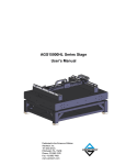
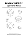
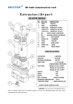
7B
Agilent 10705A Single Beam
Interferometer and Agilent 10704A
Retroreflector
Chapter 7B Agilent 10705A Single Beam Interferometer and
Agilent 10704A Retroreflector
Description
Description
The Agilent 10705A Single Beam Interferometer (shown in
Figure 7B-1) is intended for use in low-mass or limited-space
applications. This Interferometer is designed for use with the
Agilent 10704A Retroreflector (shown in Figure 7B-1); a special option
(C01-10705A, described later in this subchapter) provides an
Agilent 10705A interferometer that can be used with plane mirrors or
highly reflective surfaces.
The single beam interferometer is called that because the outgoing and
returning beams are superimposed on each other, giving the
appearance of only one beam traveling between the interferometer and
the retroreflector.
Functionally, this interferometer operates like a linear interferometer,
but is preferred when space for optics and beam paths is limited.
M IN
BEA TER
F
E
10
R
T
RE
O
EF
R
S/
L E CTO
R
R
ETE
M
O
R
SINGLE
The Agilent 10704A Retroreflector is a cube corner, but is considerably
smaller and lighter than the Agilent 10703A Retroreflector.
A
N6
4A
70
70
5A
Agilent 10705A
Single Beam Interferometer
10
Agilent 10704A
Retroreflector
Figure 7B-1. Agilent 10705A Single Beam Interferometer and Agilent
10704A Retroreflector
7B-2
User’s Manual
Chapter 7B Agilent 10705A Single Beam Interferometer and
Agilent 10704A Retroreflector
Description
When using a single-beam interferometer, the receiver is usually
mounted perpendicular to the measurement beam, and the
interferometer held stationary. An optical schematic diagram of this
interferometer is shown in Figure 7B-2.
REFERENCE and MEASUREMENT
PATHS (fA and fB )
Reference
Cube-corner
Agilent 10705A
Single Beam Interferometer
Quarter-wave
Plates
fB
Agilent 10704A
Retroreflector
fA
fA± ∆f
fB
fA
From
Laser Head
fB
fA ± ∆ f
To Receiver
LEGEND
= fA
=
= fB
= fA and fB
Rounded corners are used to help you trace paths.
Figure 7B-2. Single Beam Interferometer — laser beam path
Laser beam path
A polarizing beam-splitter reflects fB to the reference cube corner and
transmits fA to the Agilent 10704A Retroreflector (Figure 7B-2). The
return path is superimposes on the outgoing path. Since both beams
leaving the beam-splitter pass through a quarter-wave plate, the
returning polarizations are rotated through 90°. This causes fB to be
transmitted and fA ±∆f to be reflected so that they are directed
coaxially to the receiver along a path perpendicular to the input beam.
Rotating the interferometer 90° switches which optical frequency is in
the measurement path, and thus changes the direction sense.
User’s Manual
7B-3
Chapter 7B Agilent 10705A Single Beam Interferometer and
Agilent 10704A Retroreflector
Description
Differential measurements
A differential measurement is one in which both the reference beam
and the measurement beam travel to external reflectors outside the
interferometer housing. This allows measurement of the relative
positions of the two external mirrors, either or both of which may be
moving. Viewed another way, this allows measuring the motion of one
reflector relative to a reference datum elsewhere in the machine,
external to the interferometer itself. This is unlike the typical
interferometer configuration because usually the reference beam path
length does not change; in differential configurations, it can.
Take care during design and layout of a differential measurement to
avoid introduction of alignment errors, thermal or mechanical
instabilities, and potential deadpath problems. Both reflectors
(reference and measurement) should be of the same type (cube corner
or plane mirror); this minimizes thermal drift problems with ambient
temperature changes.
To use an Agilent 10705A Interferometer in a differential
measurement configuration, the reference cube corner can simply be
detached from the interferometer housing and attached to the
reference surface of interest. This is shown, using an Agilent 10702A
Interferometer for the example, in Figure 7A-7. Be aware that all
installation and alignment requirements for the measurement
reflector now apply also to the reference reflector.
Plane mirror measurements
The special option C01-10705A interferometer is an Agilent 10705A
interferometer specially modified to allow its use with plane mirrors or
highly reflective surfaces. The C01-10705A modification removes one
quarter-wave plate, resulting in an optical configuration similar to that
of the Agilent 10706A Plane Mirror Interferometer (described in
subchapter 7C of this manual); this configuration requires one
Agilent 10704A retroreflector. The C01-10705A interferometer’s
receiver signal is separated by an Agilent 10700A or Agilent 10701A
Beam Splitter.
Typical measurement mirror alignment requirements for the
C01-10705A (as a function of distance) are the same as those for the
Agilent 10706A Plane Mirror Interferometer. Agilent 10706A
interferometer specifications are given in subchapter 7C of this
manual.
7B-4
User’s Manual
Chapter 7B Agilent 10705A Single Beam Interferometer and
Agilent 10704A Retroreflector
Special Considerations
Special Considerations
Effect of optics on measurement direction sense
The orientation and configuration of the interferometer affects the
measurement direction sense. The direction sense depends on which
frequency is in the measurement path of the interferometer. For
example, if f1 (lower frequency) is in the measurement path and f2
(higher frequency) is in the reference path and the optics are moving
away from each other, the fringe counts will be INCREASING.
Interchanging f1 and f2 (perhaps by rotating the interferometer 90°,
the measurement direction sense will change. This rotation causes
switching of frequencies in the measurement path.
Configuration effects
The Agilent 10705A interferometer can be configured to turn the beam
at right angles. Be aware that doing this will cause the measurement
direction sense to be changed because the measurement reference
paths are exchanged.
Mounting
Adjustable mounts
Agilent 10710B Adjustable Mount provides a convenient means of
mounting, aligning, and securely locking in position, the Agilent
10705A interferometer. Since the mount allows some tilt and yaw
adjustment, the need for custom fixturing is minimized. This mount
allows the optic mounted on it to be rotated about its optical centerline,
simplifying installation.
Chapter 4. “System Installation and Alignment” in this manual shows
how to install an optic in various orientations, using an adjustable
mount.
Fasteners
The Agilent 10706A interferometer is designed to be used with an
Agilent 10710B Adjustable Mount, and is supplied with English
mounting hardware
User’s Manual
7B-5
Chapter 7B Agilent 10705A Single Beam Interferometer and
Agilent 10704A Retroreflector
Installation
Installation
Pre-installation checklist
In addition to reading chapters 2 through 4, and Chapter 15, “Accuracy
and Repeatability,” complete the following items before installing a
laser positioning system into any application.
Complete Beam Path Loss Calculation (see “Calculation of signal
loss” in Chapter 3, “System Design Considerations,“ of this manual).
Determine the direction sense for each axis, based on the
orientation of the laser head, beam-directing optic, and
interferometer. Enter the direction sense for each axis into the
measurement system electronics. (See Chapter 5, “Laser Heads,”
Chapter 14, “Principles of Operation,” and Chapter 15, “Accuracy
and Repeatability,” in this manual.
Provide for aligning the optics, laser head, and receiver(s) on the
machine. (Ideally, you want to be able to translate beam in two
directions and rotate beam in two directions for each interferometer
input. This typically takes two adjustment optics with proper
orientations.)
Be sure to allow for transmitted beam offset of beam splitters
(Agilent 10700A and Agilent 10701A) in your design. (See the offset
specifications under the “Specifications” heading at the end of this
subchapter.)
Refer to Chapter 4, “System Installation and Alignment,” in this
manual for installation instructions.
7B-6
User’s Manual
Chapter 7B Agilent 10705A Single Beam Interferometer and
Agilent 10704A Retroreflector
Specifications and Characteristics
Alignment
Alignment aids
Alignment aids for these interferometers are listed in Chapter 4,
“System Installation and Alignment” and Chapter 9, “Accessories,” of
this manual.
Procedure
Refer to Chapter 4, “System Installation and Alignment” in this
manual for alignment instructions.
Specifications and Characteristics
Specifications describe the device’s warranted performance.
Supplemental characteristics (indicated by TYPICAL or NOMINAL)
are intended to provide non-warranted performance information useful
in applying the device.
The basic optical resolution using a linear interferometer is one half
wavelength (0.316 micron, 12.26 microinches).
Using electronic resolution extension, the system resolution is
increased significantly. Depending on the system, an additional
resolution extension factor of 32 (for Agilent 10885A and 10895A) or
256 (for Agilent 10897B and 10898A) is usually available.
Interferometer
Fundamental Optical
Resolution
System Resolution 1
(see NOTE)
System Resolution 2
(see NOTE)
Agilent 10705A
λ /2 (316.5 nm, 12.5 µin)
λ /64 (10.0 nm, 0.4 µin)
λ /512 (1.2 nm, 0.047 µin)
NOTE
The system resolution 1 is based on using 32X electronic resolution
extension. This is available with the Agilent 10885A and
Agilent 10895A electronics.
The system resolution 2 is based on using 256X electronic resolution
extension. This is available with the Agilent 10897B and
Agilent 10898A electronics.
User’s Manual
7B-7
Chapter 7B Agilent 10705A Single Beam Interferometer and
Agilent 10704A Retroreflector
Specifications and Characteristics
Agilent 10705A Single Beam Interferometer
Specifications
Dimensions: see figure below
Weight: 85.5 grams (3.0 ounces)
Materials Used:
Housing: Stainless Steel (416)
Apertures: Plastic (Nylon)
Optics: Optical Grade Glass
Adhesives: Low Volatility (Vacuum Grade)
Maximum Transmitted Beam Deviation: ± 30 arc-minutes
Optical Efficiency (including Agilent 10703A Reflector):
Typical: 62%
Worst Case: 59%
Fundamental Optical Resolution: λ /2
Non-linearity Error: <4.2 nm (0.17 µin)
#2-56 Screws (2)
Centerline
15.2 mm
(0.60 Dia)
6-32 UNC (4 Places)
Thru Clearance
For #4 or (2.5 mm )
39.88 mm
(1.57)
SINGL
E
BE
25.65 mm
(1.01)
8.9 mm
Aperture
(0.35 Dia)
25.65
5.65 mm
(1.01)
Centerline
#2-56
4 Places
19.56 mm
(0.77) Typ
19.56 mm
(0.77)
19.56 mm
(0.77)
Figure 7B-3. Agilent 10705A Single Beam Interferometer — dimensions
7B-8
User’s Manual
Chapter 7B Agilent 10705A Single Beam Interferometer and
Agilent 10704A Retroreflector
Specifications and Characteristics
Agilent 10704A Retroreflector Specifications
Dimensions: see figure below
Weight: 10.5 grams (0.37 ounce)
Materials Used:
Housing: Stainless Steel (416)
Optics: Optical Grade Glass
Adhesives: Low Volatility (Vacuum Grade)
10.2 mm
Aperture
(0.40 Dia)
19.5 mm
(0.77)
Bolt Circle
20.5 mm
(0.81 Dia)
2.5 mm
(0.10)
2.5 mm
(0.10)
15.2 mm
(0.60 Dia)
14.3 mm
(0.56)
Figure 7B-4. Agilent 10704A Retroreflector — dimensions
Agilent 10713C 1/2-Inch Cube Corner Specifications
Dimensions: see figure below
Weight: 1.4 grams (0.05 ounce)
Nodal Point Depth: 6.33 mm (0.248 inch)
+ 0.25
- 0.00
+ 0.010
(0.500
- 0.000
12.70
mm
Dia)
11.43 mm
(0.450 Dia min.
Clear Aperture)
+ 0.00
9.53 - 0.51 mm
+ 0.000
(0.375 - 0.020 )
Figure 7B-5. Agilent 10713C 1/2-Inch Cube Corner, no housing — dimensions
User’s Manual
7B-9
Chapter 7B Agilent 10705A Single Beam Interferometer and
Agilent 10704A Retroreflector
Specifications and Characteristics
Agilent 10713D 1/4-Inch Cube Corner Specifications
Dimensions: see figure below
Weight: 0.2 grams (0.007 ounce)
Nodal Point Depth: 3.14 mm (0.123 inch)
6.35 ± 0.2 mm Dia.
(0.250 ± 0.008 in Dia.)
5.71 mm
(0.225 Dia min.
Clear Aperture)
4.75 ± 0.25 mm
(0.187 ± 0.010)
Figure 7B-6. Agilent 10713D Cube Corner, no housing — dimensions
Product specifications and descriptions in this
document subject to change without notice.
Copyright (C) 2002 Agilent Technologies
Printed in U.S.A. 07/02
This is a chapter from the manual titled:
Laser and Optics User's Manual
For complete manual, order:
Paper version: p/n 05517-90045
CD version: p/n 05517-90063
This chapter is p/n 05517-90109
7B-10
User’s Manual