1
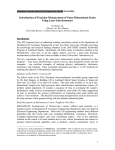
Artisan Technology Group is your source for quality
new and certified-used/pre-owned equipment
• FAST SHIPPING AND
DELIVERY
• TENS OF THOUSANDS OF
IN-STOCK ITEMS
• EQUIPMENT DEMOS
• HUNDREDS OF
MANUFACTURERS
SUPPORTED
• LEASING/MONTHLY
RENTALS
• ITAR CERTIFIED
SECURE ASSET SOLUTIONS
SERVICE CENTER REPAIRS
Experienced engineers and technicians on staff
at our full-service, in-house repair center
WE BUY USED EQUIPMENT
Sell your excess, underutilized, and idle used equipment
We also offer credit for buy-backs and trade-ins
www.artisantg.com/WeBuyEquipment
InstraView REMOTE INSPECTION
LOOKING FOR MORE INFORMATION?
Visit us on the web at www.artisantg.com for more
information on price quotations, drivers, technical
specifications, manuals, and documentation
SM
Remotely inspect equipment before purchasing with
our interactive website at www.instraview.com
Contact us: (888) 88-SOURCE | [email protected] | www.artisantg.com
3
System Design Considerations
Artisan Technology Group - Quality Instrumentation ... Guaranteed | (888) 88-SOURCE | www.artisantg.com
Chapter 3 System Design Considerations
Introduction
Introduction
Although there are many possible configurations of the laser and
optics, all Agilent laser measurement systems have these basic parts in
common:
•
A laser source, to produce the two optical frequencies f1 and f2 and
generate the reference signal. In discussions in this manual, f1 is
the lower frequency and f2 is the higher.
•
Beam-directing optics, to direct all or part of the laser beam to each
measurement axis of the system, using right-angle bends.
•
Measurement optics, to separate the two optical frequencies, direct
them over the reference and measurement paths, and recombine
them.
•
One receiver per measurement axis, to detect the difference in
optical frequencies and produce the measurement signal for that
axis.
•
Electronics to convert the measurement and reference signals into
displacement data.
Two important characteristics of Agilent interferometers must be
emphasized:
•
Only the change in relative position of the optics is detected.
•
Either optical component may move, as long as optical alignment is
maintained. If the interferometer is fixed and the retroreflector is
the moving component (toward or away from the interferometer),
motion with respect to its original position is detected. Conversely,
if the retroreflector is fixed, the interferometer can be the moving
component.
Agilent laser position transducers can detect and measure all linear
motions; that is, 3 degrees of the 18 degrees of freedom defined in the
Glossary. Small angle measurements may be made by multiple
measurements on the same axis.
The measurement system is relatively insensitive to all other motions,
as briefly described below. See Figure 3-1.
3-2
User’s Manual
Artisan Technology Group - Quality Instrumentation ... Guaranteed | (888) 88-SOURCE | www.artisantg.com
Chapter 3 System Design Considerations
Introduction
POSSIBLE COMPONENT MOTIONS
Retroreflector
Interferometer
Receiver
Z
YA
W
X LL
O
R
P Y
IT
C
H
Laser Head
Figure 3-1. Possible component motions
1. Motion of the receiver or laser head along the beam path (X) has no
effect on the measurement since both f1 and f2 would exhibit
Doppler shift.
2. Small motions of the laser head, receiver, interferometer, or
retroreflector in a direction perpendicular to the beam path (Y or Z)
have no effect on the measurement. The only restriction is that
sufficient light returns to the receiver.
3. Angular motion (pitch or yaw) of the laser head about the Z or Y
axis has the effects described below:
a. It introduces a measurement error (cosine error).
b. It may displace the laser beam so that insufficient light returns
to operate the receiver.
4. Although the laser head or the receiver may be rotated in 90°
increments about the beam axis (roll), other roll deviations from the
four optimum positions degrade the measurement signal. If either
the laser head or receiver is rotated 45° about the beam axis, all
position information will be lost because the receiver will not be
able to distinguish between the two frequencies.
5. Angular motion of the receiver about the Y or Z axis has no effect on
the measurement, within alignment limits specified for the
receiver. (Receiver specifications are given in Chapter 8,
“Receivers,” of this manual.)
6. Angular motions of the interferometer and retroreflector depend on
the particular components for limitations.
User’s Manual
Artisan Technology Group - Quality Instrumentation ... Guaranteed | (888) 88-SOURCE | www.artisantg.com
3-3
Chapter 3 System Design Considerations
Accuracy Considerations
Accuracy Considerations
Several factors outside the laser measurement system can affect
system accuracy. These factors (the measurement environment,
machine and material temperature, and the optics installation) and
their interrelationships must be understood in order to predict the
performance of the system. Detailed descriptions and methods of
compensation are given in Chapter 15, “Accuracy and Repeatability,”
of this manual.
Generally, Agilent laser measurement systems offer automatic
compensation for air environments and also for temperature changes
of the work material. For a temperature-controlled environment
(20 ±0.5° C), typical system accuracy using air sensor automatic
compensation is 1.5 ppm. Using the Agilent 10717A Wavelength
Tracker for compensation, the measurement repeatability is on the
order of ±0.2 ppm, depending on the environment.
Determining What Equipment is Needed
First, sketch out your optical configuration. Remember:
•
Each measurement axis (except for the Agilent 10717A Wavelength
Tracker) requires an interferometer and associated retroreflector.
•
Each measurement axis after the first one requires a beam splitter.
The number of beam splitters required is n-1, where n is the
number of measurement axes.
•
If an Agilent 10717A Wavelength Tracker is used, it counts as a
measurement axis.
•
If a multiaxis interferometer, such as the Agilent 10721A,
Agilent 10735A, Agilent 10736A, or Agilent 10737L,R is used, be
sure the beam-directing optics you select will provide enough laser
beam power to drive the receivers through the multiple
measurement paths of the interferometer.
•
Beam benders should be arranged so their exiting beams are
perpendicular to one polarization plane of the incoming laser beam.
•
Rotation of the beam during bending can result in problems due to
the effects of polarization.
•
Beam splitters should be arranged so:
3-4
User’s Manual
Artisan Technology Group - Quality Instrumentation ... Guaranteed | (888) 88-SOURCE | www.artisantg.com
Chapter 3 System Design Considerations
Determining What Equipment is Needed
–
one exiting beam is along the axis of the incoming beam, and
the second beam is perpendicular to one polarization of the
incoming beam, as described above for beam benders.
– Each measurement axis requires an interferometer. The nature
of the measurement(s) to be made influences the interferometer
choice.
– Each measurement axis (including the Agilent 10717A
Wavelength Tracker) requires a receiver. The interferometer
used can influence the receiver choice. Note that the
Agilent 5519A and Agilent 5519B laser heads include a built-in
receiver.
Then, from your layout, determine your optics needs. Choose the
Agilent laser head, optical and electronic components accordingly.
Decide on a compensation scheme and, finally, select cables. Table 3-1
summarizes the equipment choices. For advice and help, contact
Agilent Technologies.
Table 3-1. Equipment choices
Component
Comment(s)
Laser
One required per system
Agilent 5517A
Lowest velocity, largest size, 6 mm beam
Agilent 5517B
25% higher velocity than Agilent 5517A, small size, 6 mm beam
Agilent 5517C
Std
5517C-003
5517C-009
Higher velocity than Agilent 5517A and 5517B, small size
6 mm beam diameter
3 mm beam diameter
9 mm beam diameter
Agilent 5517D
Highest velocity, small size, 6 mm beam
Agilent 5519A
Largest size, built-in receiver and power supply used in the
Agilent 5529A Dynamic Calibrator System and Metrology
applications.
Agilent 5519B
Largest size, built-in receiver and power supply, higher velocity than
Agilent 5519A; used in the Agilent 5529A Dynamic Calibrator
System and Metrology applications.
Beam-Directing Optics
Order as required to manipulate beam path to your
configuration
Agilent 10567A
Dual-Beam Beam Splitter, useful in vacuum applications
Agilent 10700A
33% Beam Splitter
Agilent 10701A
50% Beam Splitter
Agilent 10707A
Beam Bender
Agilent 10725A
50% Beam Splitter, no housing
Agilent 10726A
Beam Bender, no housing
Agilent N1203C
Precision Beam Translator
Agilent N1204C
Precision Horizontal Beam Bender
User’s Manual
Artisan Technology Group - Quality Instrumentation ... Guaranteed | (888) 88-SOURCE | www.artisantg.com
3-5
Chapter 3 System Design Considerations
Determining What Equipment is Needed
Table 3-1. Equipment choices (Continued)
Component
Comment(s)
Beam-Directing Optics (Continued)
Agilent N1207C
Precision Vertical Beam Bender
Measurement Optics
One Interferometer-plus-Reflector pair required per axis
Agilent 10702A
Linear Interferometer
Agilent 10702A-001
Same as above, but with wedge windows — required if
interferometer is the moving component.
Agilent 10703A
Reflector — paired with Agilent 10702A
Agilent 10704A
Reflector — paired with Agilent 10705A
Agilent 10705A
Single Beam Interferometer
Agilent 10706A
Plane Mirror Interferometer
Agilent 10706B
High Stability Plane Mirror Interferometer
Agilent 10715A
Differential Interferometer
Agilent 10715A-001
Differential Interferometer, turned configuration
Agilent 10716A
High Resolution Interferometer
Agilent 10716A-001
High Resolution Interferometer, turned configuration
Agilent 10717A
Wavelength Tracker (requires measurement receiver and cable)
Agilent 10719A
One-axis Differential Interferometer, requires 3 mm beam from
Agilent 5517C-003
Agilent 10721A
Two-axis Differential Interferometer, requires 3 mm beam from
Agilent 5517C-003
Agilent 10724A
Plane Mirror Reflector
Agilent 10735A
Three-axis Interferometer
Agilent 10736A
Three-axis Interferometer
Agilent 10736A-001
Three-axis Interferometer with Beam Bender
Agilent 10737L
Compact three-axis Interferometer, left
Agilent 10737R
Compact three-axis Interferometer, right
Agilent 10766A
Linear Interferometer
Agilent 10767A
Linear Retroreflector — paired with Agilent 10766A
Agilent 10767B
Lightweight Retroreflector
Agilent 10770A
Angular Interferometer
Agilent 10771A
Angular Retroreflector — paired with Agilent 10770A
Agilent 10774A
Short Range Straightness Optics (matched set)
Agilent 10775A
Long Range Straightness Optics (matched set)
3-6
User’s Manual
Artisan Technology Group - Quality Instrumentation ... Guaranteed | (888) 88-SOURCE | www.artisantg.com
Chapter 3 System Design Considerations
Determining What Equipment is Needed
Table 3-1. Equipment choices (Continued)
Component
Comment(s)
Optic Mounts
Adjustable mounts simplify installation and alignment
Agilent 10710B
Use with Agilent 10700A, 10701A, 10705A, 10707A
Agilent 10711A
Use with Agilent 10702A, 10706A, 10706B, 10715A, 10716A
Measurement Receivers
One required per axis; one required with Agilent 10717A
Wavelength Tracker (if used)
Agilent 10780C
Receiver
Agilent 10780F
Remote Receiver
Agilent E1708A
Remote Dynamic Receiver
Agilent E1709A
Remote High-Performance Receiver
Receiver Cables for use with Agilent 10895A VME Axis board — one cable per system
Agilent 10790A
5 meters long
Agilent 10790B
10 meters long
Agilent 10790C
20 meters long
Receiver Cables for use with Agilent 10885A PC Axis Board or Agilent N1231A PCI
Three-Axis Board — one cable per receiver
Agilent 10880A
5 meters long
Agilent 10880B
10 meters long
Agilent 10880C
20 meters long
Laser Head Cables for Agilent 5517A/B/C/D Laser Head used with Agilent 10885A, 10889B,
or N1231A axis boards (cable has a DIN connector for connecting to the Agilent 10884A Power
Supply to provide power to the laser head) — one cable per system
Agilent 10881A
3 meters long
Agilent 10881B
7 meters long
Agilent 10881C
20 meters long
Laser Head Cables for Agilent 5517A/B/C/D Laser Head used with Agilent 10885A, 10889B,
or N1231A axis boards (cable has spade lugs for connection to a power supply to provide power
to the laser head)— one cable per system
Agilent 10881D
3 meters long
Agilent 10881E
7 meters long
Agilent 10881F
20 meters long
Laser Head Cables for Agilent 5519A/B Laser Head used with Agilent 10887P
Programmable PC Calibrator Board in the Agilent 5529A system— one cable per system
Agilent 10882A
3 meters long
Agilent 10882B
7 meters long
Agilent 10882C
20 meters long
User’s Manual
Artisan Technology Group - Quality Instrumentation ... Guaranteed | (888) 88-SOURCE | www.artisantg.com
3-7
Chapter 3 System Design Considerations
Determining What Equipment is Needed
Table 3-1. Equipment choices (Continued)
Component
Comment(s)
Accessory Reflectors
Order as required for your application
Agilent 10728A
Plane Mirror
Agilent 10769A
Beam Steering Mirror
Agilent 10772A
Turning Mirror
Agilent 10773A
Flatness Mirror
High Performance Laser Head Cable for Agilent 5517B/C/D Laser Head used with the
Agilent 10897B and 10898A VME Axis boards, and N1231A PCI Axis board (cable has a
DIN connector for connecting to the Agilent 10884A Power Supply to provide power to the laser
head) — one cable per system
Agilent N1251A
3 meters (9.8 feet)
Agilent N1251B
7 meters (23.0 feet)
High Performance Receiver Cables for use with Agilent 10897B and 10898A VME Axis
boards, and N1231A PCI Axis board — one cable per receiver
Agilent N1250A
5 meters (16.4 feet)
Agilent N1250B
10 meters (32.8 feet)
3-8
User’s Manual
Artisan Technology Group - Quality Instrumentation ... Guaranteed | (888) 88-SOURCE | www.artisantg.com
Chapter 3 System Design Considerations
Electronic Components
Electronic Components
Transducer Systems
There are three different types of electronics for Agilent laser
transducer systems. These electronics use different backplanes and
have different performance and outputs. Full details are given in the
appropriate electronics system manuals.
PC-Based Electronics
The Agilent 10885A PC Axis Board is compatible with PC (ISA)
backplanes.
Up to six Agilent 10885As may be used in a single system.
VME Compatible Electronics
The Agilent 10898A High Resolution VMEbus Dual Laser Axis Board,
Agilent 10897B High Resolution VMEbus Laser Axis Board, and
Agilent 10895A VMEbus Laser Axis Board are compatible with VME
backplanes.
The Agilent 10896B VME Laser Compensation Board is also
compatible with VME backplanes and works with the Agilent 10895A.
Up to six Agilent 10895As and several Agilent 10896As (up to one for
each Agilent 10895A) may be used in a single system.
PC-Based PCI Electronics
The Agilent N1231A PCI Three-Axis Board is optimized for connection
to a PMAC motion control system from Delta Tau®. It is a full size,
Universal (3.3V and 5.0V signaling compatibility), 32-bit, 33 MHz, PCI
Rev. 2.2 compliant card for use in PC-compatible controllers as part of
an Agilent laser interferometry position measurement system.
User’s Manual
Artisan Technology Group - Quality Instrumentation ... Guaranteed | (888) 88-SOURCE | www.artisantg.com
3-9
Chapter 3 System Design Considerations
Electronic Components
Calibrator System Electronics
Agilent 5529A Dynamic Calibrator
The Agilent 5529A Dynamic Calibrator is a laser system used to
ensure the accuracy of a machine’s motion and positioning. Controlled
through your PC (with Microsoft® Windows installed), the system is
able to collect and analyze measurement data for a number of
measurements. The Agilent 5529A Dynamic Calibrator typically
includes the following electronic components:
•
Agilent 5519A/B Laser Head
•
Agilent 10886A PC Compensation board (optional, for automatic
compensation)
•
Agilent 10887B PC Calibrator Board
•
Agilent 10751C,D Air sensor and Agilent 10757D,E,F Material
Temperature sensor(s) (optional, as required)
•
Agilent 10888A Remote Control units (optional)
The PC compensation boards provide the interfaces between the air
and material temperature sensors and your PC. The boards convert the
analog electrical voltages from the sensors to digital forms that the PC
uses to calculate the compensation factors. These factors adjust for
changes in the systems’ operating environments. Typical sensors used
with each Agilent 10886A PC Compensation board are the
Agilent 10751C,D Air Sensor and one to three Agilent 10757D,E,F
Material Temperature sensors.
The Agilent 10887B PC Calibrator Board enable the PC to perform
laser calibrator-related functions with the Agilent 5529A calibrator
software.
An Agilent Two-Axis 5529A/5529A Dynamic Calibrator and an
Agilent 55292A USB Expansion Module are also available. The USB
software hosts up to five axes on one computer.
3-10
User’s Manual
Artisan Technology Group - Quality Instrumentation ... Guaranteed | (888) 88-SOURCE | www.artisantg.com
Chapter 3 System Design Considerations
Adjustment Considerations
Adjustment Considerations
In general, when aligning the Agilent optics, it will be necessary to
adjust most or all of the optical components. Most optics are not
referenced to their housings since simple adjustments by the user can
usually provide optimum alignment. The Agilent 10710B and
Agilent 10711A Adjustable Mounts should be used to provide the
adjustment capability for most optical components.
There are a few exceptions, however. Certain optics designed for
multiaxis systems provide referenced housings. Installation and
alignment of these optics depends on the optic; refer to specific
instructions for these optics (Agilent 10719A, Agilent 10721A,
Agilent 10735A, Agilent 10736A) elsewhere in this manual.
Other optics require you to fabricate your own mounts.
In general, the alignment procedures are performed with all optical
components in place. Your measurement system design should allow
for adjustment of the laser, optics, and receivers during alignment.
Laser beam and optics protection
The laser measurement system requires protection against
unintentional laser beam blockage and air turbulence problems. In
some applications, such as machine tools, protection should be
provided to prevent metal chips or cutting fluid from interfering with
the measurements. Also, the optical components usually require
protection to prevent contamination of the optical surfaces by oil or
cutting fluid. In applications which are considered “clean”, protection
may not be needed.
If protection of the laser beam and optical components is required,
there are two general types: moving-component protection and
stationary component protection.
In many applications, the only moving component is the interferometer
or the reflector. Many of the beam benders are stationary and only
direct the laser beam to the measurement axis. In these cases, it is only
necessary to provide fixed tubing for the laser beam and some type of
sealed enclosure for the optics. Since only one laser beam of
approximately 6 mm (0.24 inch) in diameter is involved, relatively
small diameter tubing can be used. Since either the interferometer or
the reflector is moving during the measurement, protecting the laser
beam and the moving components requires a telescoping cover or a
cover that is self-sealing. A wide variety of commercially available
protective covers are suitable for this purpose.
User’s Manual
Artisan Technology Group - Quality Instrumentation ... Guaranteed | (888) 88-SOURCE | www.artisantg.com
3-11
Chapter 3 System Design Considerations
Adjustment Considerations
Figure 3-2 illustrates techniques for protecting the laser beam and
optical components with different types of protective covering. Note
that the cover for the retroreflector allows the retroreflector to be
moved very close to the interferometer. This helps minimize the
deadpath errors. Chapter 15, “Accuracy and Repeatability,” in this
manual has more details on minimizing deadpath.
V
IE
W
Moving
Interferometer
IN
E
S
LI
D
E
S
E
E
Protective Cover
A
PROTECTIVE COVERS
F
TA IXE
B D
LE
M
A
X
C
H
Fixed Conduit
For Laser Beam
Fixed Interferometer
Protective Cover
Receiver
To
Electronics
Laser Beam
Moving
Interferometer
Flexible Seal
Protective Cover
Machine
Slide
Fixed Table
VIEW A
Figure 3-2. Protective covers for optics and laser beam
3-12
User’s Manual
Artisan Technology Group - Quality Instrumentation ... Guaranteed | (888) 88-SOURCE | www.artisantg.com
Chapter 3 System Design Considerations
Adjustment Considerations
Figure 3-3 shows a different type of protective cover. Again, the
mechanical arrangement allows the retroreflector to be close to the
interferometer at the closest point of travel, even though the
telescoping cover is not entirely collapsible. Another type of protective
cover is the flexible bellows. This is generally used for short travel
distances.
COLLAPSIBLE SPIRAL COVER
Machine Saddle
Moving Retroreflector
Collapsible
Spiral Cover
Fixed Interferometer
Receiver
To Electronics
Fixed Conduit
For Laser Beam
Laser Beam
Figure 3-3. Collapsible spiral cover for movable retroreflector
User’s Manual
Artisan Technology Group - Quality Instrumentation ... Guaranteed | (888) 88-SOURCE | www.artisantg.com
3-13
Chapter 3 System Design Considerations
System Grounding
System Grounding
Be sure to consider electrical grounding requirements as you plan and
install your Agilent laser measurement. Grounding is important for
safety reasons, but your grounding arrangement can also affect your
laser system’s performance.
Best practice requires that all system components that are connected
to electrical ground should be connected to ground at a common point,
not at separate points. Your electrical ground connections should
radiate from a single point. Using more than one grounding point could
create a ground loop, which could introduce an unacceptable level of
electrical noise into the electronics.
Signal grounds on each Agilent laser head, each Agilent receiver and
the Agilent laser measurement system electronics are all connected to
their respective chassis. To prevent ground loops they all should be
grounded through one common point.
The Agilent 10780C or Agilent 10780F receiver mounting is isolated
from ground by using the nylon screws supplied.
A system using VME electronics (Agilent 10898A, Agilent 10897B, and
Agilent 10895A axis boards), PC electronics (Agilent 10885A axis
board) or PCI electronics (N1231A axis board) should be grounded
through the electronics power line.
3-14
User’s Manual
Artisan Technology Group - Quality Instrumentation ... Guaranteed | (888) 88-SOURCE | www.artisantg.com
Chapter 3 System Design Considerations
Laser Head
Laser Head
Orientation
An Agilent laser head may be mounted in any orientation as long as it
is positioned to direct the beam into the optical system parallel to or
orthogonal with the machine axes being measured. See Chapter 5,
“Laser Heads,” in of this manual for more information about laser head
orientation.
Mounting plane tolerance
The plane defined by the three mounting feet on the laser head must be
parallel to either the bottom or sides of the beam-splitters and of the
beam-bender housings to within ± 3°, and to the bottom or sides
interferometers to within ± 11°. This ensures that the polarization axes
of the interferometers are oriented properly relative to the polarization
vectors of the laser beam (Figure 3-4). The laser head can be rotated in
90° increments about the beam axis (roll) without affecting the system
performance, but the measurement direction sense will change with
each 90° rotation.
Allow 50 mm (2 inches) clearance around the laser head for easy
servicing.
Allow at least 100 mm (4 inches) clearance at the back of the laser head
for cable connections.
User’s Manual
Artisan Technology Group - Quality Instrumentation ... Guaranteed | (888) 88-SOURCE | www.artisantg.com
3-15
Chapter 3 System Design Considerations
Laser Head
LASER POSITION TRANSDUCER MOUNTING
Beam Splitter
90
˚±
3˚
Beam Bender
90˚
±3
90˚
˚
±3
˚
Figure 3-4. Laser position transducer mounting
Pointing stability
To maintain good pointing stability, it is good practice to use kinematic
mounting principles. Refer to Chapter 5, “Laser Heads,” in this manual
for more information about laser head pointing stability.
Thermal isolation
Because there is some heat dissipation from the laser heads, you
should choose the mounting method and location with care. Where
possible, mount the laser head away from the measuring area, to avoid
any thermal effects.
Vibration isolation
Since the system measures only the relative motion between the
interferometer and reflector, measurements are not affected by
vibration along the beam axis of the laser source or the receiver.
3-16
User’s Manual
Artisan Technology Group - Quality Instrumentation ... Guaranteed | (888) 88-SOURCE | www.artisantg.com
Chapter 3 System Design Considerations
Optics
When vibration of the laser head causes displacement of the beam
(perpendicular to beam axis) at an interferometer or receiver, the beam
signal power can fluctuate. If this fluctuation is too great, insufficient
beam signal will arrive at the receiver, causing a “measurement signal
error.”
Magnetic shielding
Agilent laser heads contain a permanent magnet. When installing an
Agilent laser measurement system in an application sensitive to
magnetic fields, shielding around the laser head may be required.
Mounting
See Chapter 5, “Laser Heads,” in this manual for laser head
installation and mounting instructions.
The laser source in Agilent 5517C-009 9-mm Laser Head is referenced
to locations on the outside of the laser head, allowing the laser head to
be installed in a predefined mounting location, minimizing the need for
laser head alignment. A diagram of the mounting location for this laser
head is presented in Figure 3-16.
Optics
Plane of orientation with respect to laser head
The mounting plane tolerance of the optics to the laser head is the
same as discussed in the paragraph titled “Mounting plane tolerance,”
above. That is, the bottom or sides of the interferometers should be
parallel to within ± l° of the plane defined by the laser head’s three
mounting feet.
Effect of optics on measurement direction sense
The orientation and configuration of the interferometers affects the
measurement direction sense. The direction sense depends on which
frequency is in the measurement path of the interferometer. For
example, if f1 (lower frequency) is in the measurement path and f2
(higher frequency) is in the reference path and the optics are moving
away from each other, the fringe counts will be INCREASING. This
corresponds to using an Agilent 5517A, Agilent 5517B, or
Agilent 5517C Laser Head (mounting feet in horizontal plane) with an
Agilent 10702A Linear Interferometer mounted with labels facing up
and down (see Figure 3-5). Interchanging f1 and f2 (e.g., rotating
interferometer 90°) in this example will result in the fringe counts
DECREASING.
User’s Manual
Artisan Technology Group - Quality Instrumentation ... Guaranteed | (888) 88-SOURCE | www.artisantg.com
3-17
Chapter 3 System Design Considerations
Optics
The optical schematics for the interferometers, in Chapter 7
“Measurement Optics,” show which frequency polarizations are in the
measurement path.
DIRECTION SENSE
Reference
Cube-Corner
f2
f1
f1 ±
f2
f
f2
Agilent 10703A
Retroreflector
f1
Agilent 10702A
Linear Interferometer
f1 ±
f
LEGEND
= f1
= f2
= f1 and f2
Figure 3-5. Direction sense - fringe counts increase as optics move
apart
As with the laser heads, when the interferometers are rotated 90°, the
measurement direction sense will change. This rotation causes
switching of frequencies in the measurement path.
Configuration effects
Many of the distance-measuring interferometers can be configured to
turn the beam at right angles. When configuring the linear,
single-beam, and plane mirror interferometers to turn the beam, the
measurement direction sense will be changed. This is because the
measurement and reference paths are switched on the interferometers,
therefore changing the direction sense. For more information, see the
Chapter 7, “Measurement Optics,” in this manual.
3-18
User’s Manual
Artisan Technology Group - Quality Instrumentation ... Guaranteed | (888) 88-SOURCE | www.artisantg.com
Chapter 3 System Design Considerations
Optics
Vibration isolation for optics
Vibration of the optics along the beam can cause the fringe count in the
laser measurement system electronics to fluctuate rapidly. Vibrations
along this axis constitute real, measurable, displacements; you will
have to decide if these fluctuating measurements are acceptable in
your application. In extreme cases, however, the velocity of the optics
may momentarily exceed the velocity limitation of the laser system,
causing an error.
When vibration occurs perpendicular to the beam, the beam signal
power can fluctuate. If this fluctuation is too great, insufficient beam
signal will arrive at the receivers, causing a “measurement signal
error”.
Loose mounting can cause the optics to move inappropriately during a
measurement, causing a measurement error or loss of beam power.
Elastic mounting can have the same effect as loose mounting. It can
also be responsible for a “sag” offset in the optics’ positions. If there is
vibration in the machine, an elastic mounting can transmit and
amplify the vibration to the attached optic, possibly causing more
errors. You should anticipate these effects and minimize them, if
necessary, during the laser measurement system design process.
Certain interferometers are inherently less susceptible to vibration
effects than others. This is particularly true of differential-style
interferometers such as the Agilent 10715A, Agilent 10719A, and
Agilent 10721A. The stability of these interferometers is due to the fact
that both their reference beams and their measurement beams travel
to external mirrors. Any motion of the interferometer itself that is
common to both beams will not appear as a measurement. Of course,
any vibration between the reference and measurement mirrors will
constitute real, measurable, displacements.
Adjustable mounts for optics
The optical elements inside several of the Agilent laser measurement
system optics are not precisely referenced to their housings. In most
applications involving these optics, a few simple alignments during
system installation can usually provide equal or better alignment than
referencing the optics to their housings. Therefore, slight positioning
adjustments of the unreferenced interferometers, beam splitters, and
beam benders are needed for proper system alignment.
User’s Manual
Artisan Technology Group - Quality Instrumentation ... Guaranteed | (888) 88-SOURCE | www.artisantg.com
3-19
Chapter 3 System Design Considerations
Optics
Positioning adjustments for most optics can be provided by using
Agilent 10710B or Agilent 10711A Adjustable Mounts, as appropriate.
These mounts allow adjustment of pitch and yaw of any attached optic.
(Roll adjustment is typically not required, and can usually be avoided
by careful optical system layout.)
For a listing of which Adjustable Mount supports which optic, see the
Chapter 9, “Accessories,” in this manual.
In some applications, referenced housings can provide significant
advantages. For example, the alignment requirements for certain
multiaxis applications can be difficult or impossible to achieve without
referenced housings. In those cases, interferometers such as the
Agilent 10719A, Agilent 10721A, Agilent 10735A, and Agilent 10736A
should be considered. These products have referenced housings and
prealigned optical elements. Because they have individual mounting
requirements, these products are not intended for use with the
adjustable mounts described above. For more information about these
optics, refer to Chapter 7, “Measurement Optics,” in this manual.
Fasteners for optics
Any optical component that fits an adjustable mount is supplied with
mounting screws to mount it on the appropriate adjustable mount.
Vacuum applications
There are vacuum options for Agilent optical components, which are
compatible with vacuum environments. Contact Agilent Call Center
for information (telephone numbers of various call centers are listed on
the “Service and Support” page at the back of this manual). The
housings of these components are made of stainless steel and the
optical elements are attached to these housings using a low volatility
(space grade) adhesive. See the “Specifications” information for each
optic for a list of materials used in the optic.
If the laser beam has to go through a window (for example into a
vacuum chamber) the window must meet the following requirements:
1. A minimum window aperture of 25.4 mm (1 inch) with a minimum
thickness of 8 mm (0.3 inch). If a larger window is used, it must be
proportionally thicker to assure no distortion in the window when
under differential pressures.
2. Transmitted wavefront distortion less than λ /10 (peak-valley,
single-pass) over a 23 mm (0.9 inch) diameter.
3. Parallelism of faces less than ±2 arc-minutes, to reduce beam
steering.
3-20
User’s Manual
Artisan Technology Group - Quality Instrumentation ... Guaranteed | (888) 88-SOURCE | www.artisantg.com
Chapter 3 System Design Considerations
Optics
4. Surface quality 60-40 or better, per Mil-0-13830.
5. The window must be strain-free.
Differential measurements with interferometers
Several interferometers have the capability to make differential
measurements. A differential measurement is one in which both the
reference beam and the measurement beam travel to external mirrors
outside the interferometer housing. This allows measurement of the
relative positions of the two external mirrors, either or both of which
may be moving. Viewed another way, this allows measuring the motion
of one reflector relative to a reference datum elsewhere in the machine,
external to the interferometer itself. This is unlike the typical
interferometer configuration because usually the reference beam path
length does not change; in differential configurations, it can.
One useful example of a differential measurement in a lithography
application is for measuring the motion of the X-Y stage relative to the
optical column. The Agilent 10719A One-Axis Differential
Interferometer (shown in Figure 7J-I of subchapter 7J) and the
Agilent 10721A Two-Axis Differential Interferometer (shown in Figure
7K- 1 of subchapter 7K) are ideally suited to this type of measurement,
because they provide parallel reference and measurement paths which
are offset vertically by 19 mm (0.750 inch). For such an application, a
user-supplied reference plane mirror is required in addition to the
measurement reflector on the X-Y stage.
The Agilent 10715A interferometer (shown in Figure 7G-1) also
permits differential measurements between two plane mirrors.
However, instead of having an offset spacing as in the Agilent 10719A
or Agilent 10721A, the Agilent 10715A permits the reference beams
and the measurement beams to be aligned essentially coaxially. A
specially-shaped reference plane mirror is supplied with the
Agilent 10715A.
Customized differential configurations are possible with several other
interferometers. However, considerable care should be exercised
during design and layout to avoid introduction of alignment errors,
thermal or mechanical instabilities, and potential deadpath problems.
When making differential measurements, both reflectors (reference
and measurement) should be of the same type (cube corner or plane
mirror); this minimizes thermal drift problems with ambient
temperature changes.
User’s Manual
Artisan Technology Group - Quality Instrumentation ... Guaranteed | (888) 88-SOURCE | www.artisantg.com
3-21
Chapter 3 System Design Considerations
Optics
To use the Agilent 10702A, Agilent 10705A, or Agilent 10766A in a
differential configuration, the reference cube corner can simply be
detached from the interferometer housing and attached to the
reference surface of interest. This is shown in Figure 7A-7. Be aware
that all installation and alignment requirements for the measurement
reflector now apply also to the reference reflector.
To use the Agilent 10706A or Agilent 10706B interferometer in a
differential configuration, a plane mirror is recommended as the
reference reflector. Simply replace the reference cube corner (or
high-stability adapter) with the Agilent 10722A Plane Mirror
Converter and attach the reference plane mirror to the reference
surface of interest. This is shown in Figure 7C-4. Again, install and
align the reference reflector the same as you would the measurement
reflector.
Moving interferometer instead of reflector
When moving the interferometer instead of the measurement reflector
is required, the Agilent 10702A-001 (or Agilent 10766A) should be
used. In practice, for alignment reasons, these are the only
interferometers (except the straightness interferometers) that can be
moved while making measurements. For a detailed explanation of why
this option is required, see Figure 7A-2.
Introducing an offset into the laser beam
There may be an occasion when you will want to simply introduce an
offset into your laser beam, to get it from the laser head to the
interferometer without having to relocate either one of them.
Figure 3-6 shows two ways in which this can be done.
To simply translate the beam, you can use two reflectors (such as the
Agilent 10726A Beam Bender) as a “periscope”, as shown in
Figure 3-6(A). Changing the spacing between the reflectors, or rotating
the device can change the amount of offset.
To reverse the direction of the beam, you can use two reflectors in a
“retroreflector” arrangement as shown in Figure 3-6(B).
3-22
User’s Manual
Artisan Technology Group - Quality Instrumentation ... Guaranteed | (888) 88-SOURCE | www.artisantg.com
Chapter 3 System Design Considerations
Beam Path Loss Computation
Beam Path Loss Computation
Multiaxis positioning systems must be designed to allow sufficient
optical power to reach each Agilent 10780C, Agilent 10780F,
Agilent E1708A, or Agilent E1709A Receiver in the system.
Since all optics have an efficiency of less than 100%, an optical power
loss budget must be created as a part of any multiaxis system design.
This chapter defines optical efficiency as it relates to the signal loss
through components. A method for computing the optical power loss in
a system is described.
Considerations
The following considerations are important in designing a reliable
multiaxis measuring system:
•
When using the Agilent 10780C/F or Agilent E1708A receivers,
typically up to four measurement axes can be easily implemented
without optical power loss imposing significant constraints. A
system of five or six axes is usually feasible, although closer
attention to the power loss budget is required. A system having
more than six axes is possible under certain circumstances (with
PC- or VME-based electronics), but the optical power loss budget
quickly becomes the limiting constraint. The Agilent E1709A
receiver was designed for systems that have more than six
measurement axes.
•
Minimum laser output power is 120 microwatts for the laser heads.
The typical laser output power is about 400 microwatts. The output
power is relatively constant over the life of the tube, and tends to
drop off immediately at the end.
•
Higher laser output power is available upon request.
User’s Manual
Artisan Technology Group - Quality Instrumentation ... Guaranteed | (888) 88-SOURCE | www.artisantg.com
3-23
Chapter 3 System Design Considerations
Beam Path Loss Computation
INTRODUCING AN OFFSET
A: Offset Only
To Other Optics
T
90%
90%
From Laser Head
B: Offset Plus Direction Change
To Other Optics
90%
90%
From Laser Head
Figure 3-6. Introducing an offset into the laser beam
•
Minimum required power at the Agilent 10780C Receiver is
1.5 microwatts. The Agilent 10780F Remote Receiver and
Agilent E1708A Remote Dynamic Receiver require 2.2 microwatts
with its standard 2-meter fiber-optic cable (more with longer
cables). The Agilent E1709A Remote High-Performance Receiver
requires a minimum of 0.20 to 0.80 microwatts, depending on the
AC/DC ratio, with standard 2-meter plastic fiber-optic cable.
(Adjustment of the receiver’s gain is required to obtain this
sensitivity. See the alignment and gain adjustment procedures in
Chapter 8, “Receivers,” of this manual.)
3-24
User’s Manual
Artisan Technology Group - Quality Instrumentation ... Guaranteed | (888) 88-SOURCE | www.artisantg.com
Chapter 3 System Design Considerations
Beam Path Loss Computation
•
The beam splitters have “worst-case” as well as “typical”
transmission and reflection specifications. Refer to the paragraphs
titled “Axis component efficiencies (worst case)” and “Axis
component efficiencies (typical)” on the following pages, for these
specifications.
•
In addition, all optics have small reflection and absorption losses
that occur at each internal interface or component, which is taken
into account in their efficiency value.
•
Fingerprints, dirt, or oil on a glass surface significantly reduce
optical efficiency by increasing both reflection and absorption
losses.
•
System misalignment also reduces the amount of light reaching the
receiver.
•
Thermal gradients in the beam path can bend the beam and distort
the wave front, both of which reduce optical signal strength at the
receiver.
Calculation of signal loss
In order to assess the signal loss in a measurement system, each
optical component has been characterized by both worst case and
typical optical efficiencies. These efficiency values for each optical
component are listed in the “Specifications” section for each optic (that
is, the specifications section in Chapter 6, “Beam-Directing Optics,” for
beam splitters and Chapter 7, “Measurement Optics,” for
interferometers.)
Optical efficiency is defined as:
Optical Power O u t
Efficiency = ----------------------------------------------------Optica l Power In
The optical efficiencies for the interferometers are given with the
respective measurement reflector efficiency included. For example, the
Agilent 10702A Linear Interferometer efficiency includes the efficiency
of the Agilent 10703A Retroreflector.
The combined optical efficiency of a given measurement axis is the
product of the efficiencies of the individual optics in the beam path.
This combined efficiency times the minimum laser output power in
microwatts yields the worst case optical power at the receiver. This
value must be at least 1.5 microwatts for the Agilent 10780C Receiver,
or 2.2 microwatts for the Agilent 10780F Remote Receiver and
Agilent E1708A Remote Dynamic Receiver, or 0.20 to 0.80 microwatts
for Agilent E1709A Remote High-Performance Receiver. A beam power
User’s Manual
Artisan Technology Group - Quality Instrumentation ... Guaranteed | (888) 88-SOURCE | www.artisantg.com
3-25
Chapter 3 System Design Considerations
Beam Path Loss Computation
safety factor of at least three is recommended even though worst case
laser and optics are assumed. Creating a system with five or more axes
of measurement may result in a beam power safety factor that is less
than three.
As an example, consider a typical installation with two measurement
axes and a Wavelength Tracker axis (Figure 7I-3). Assume differential
interferometers, good optical alignment, 98% efficient plane mirrors
(on the stage), comparable path lengths, and use of any Agilent laser
head.
The three axes — X, Y, and Wavelength Tracker (WT) — have the
components listed in the following table.
Axis component efficiencies (worst case)
Axis
Component
Component Efficiencies
(Worst Case)
X
Agilent 10700A (67% path)
61%
X
Agilent 10701A
39%
X
Agilent 10715A
25%
Y
Agilent 10700A (67% path)
61%
Y
Agilent 10701A
39%
Y
Agilent 10715A
25%
W
Agilent 10700A (33% path)
27%
W
Agilent 10707A
98%
W
Agilent 10717A
25%
Assuming a minimum laser power of 120 microwatts, you can calculate
the worst-case power at the X, Y, and Wavelength Tracker receivers by
multiplying the product of component efficiencies by the laser output
power:
Power at X = 0.61 × 0.39 × 0.25 × 120 = 7.1
Power at Y = 0.61 × 0.39 × 0.25 × 120 = 7.1
Power at WT = 0.27 × 0.98 × 0.25 × 120 = 7.9
This system has a power safety factor of 4.7 at worst case (based on use
of the Agilent 10780C Receiver, which requires 1.5 microwatts) for
each axis resulting in reliable operation and easy alignment.
3-26
User’s Manual
Artisan Technology Group - Quality Instrumentation ... Guaranteed | (888) 88-SOURCE | www.artisantg.com
Chapter 3 System Design Considerations
Beam Path Loss Computation
You can also calculate this safety factor using the typical optical
efficiency values, listed in the following table.
Axis component efficiencies (typical)
Axis
Component
Component Efficiencies
(Typical)
X
Agilent 10700A (67% path)
63%
X
Agilent 10701A
45%
X
Agilent 10715A
36%
Y
Agilent 10700A (67% path)
63%
Y
Agilent 10701A
45%
Y
Agilent 10715A
36%
W
Agilent 10700A (33% path)
30%
W
Agilent 10707A
99%
W
Agilent 10717A
36%
Using the typical laser power of 400 microwatts, you can calculate the
typical power at the X, Y, and Wavelength Tracker receivers by
multiplying the product of each component efficiency by the laser
output power for each axis.
Power at X = 0.63 × 0.45 × 0.36 × 400 = 40.8
Power at Y = 0.63 × 0.45 × 0.36 × 400 = 40.8
Power at WT = 0.30 × 0.99 × 0.36 × 400 = 42.8
By using the typical efficiencies of the component, a safety factor
greater than 28 is achieved (based on use of the Agilent 10780C
Receiver, which requires 1.5 microwatts). The Agilent 10780F
(2.2 microwatts), Agilent E1708A (2.2 microwatts), and
Agilent E1709A (0.20 to 0.80 microwatts) receivers are more sensitive.
Hence, can operate with more axes.
User’s Manual
Artisan Technology Group - Quality Instrumentation ... Guaranteed | (888) 88-SOURCE | www.artisantg.com
3-27
Chapter 3 System Design Considerations
Receivers
Receivers
General
When determining the receiver mounting locations and positions, keep
the following points in mind:
1. At a 45° position (roll), the signal will go to zero.
2. The receiver typically dissipates 2.0 Watts, with a maximum
dissipation of 2.7 Watts. Plastic pads keep an air gap around the
receiver and act as thermal and electrical isolators.
CAUTION
Use nylon screws only (Agilent 2360-0369). The receiver housing must
be electrically isolated from the mounting fixture.
3. The remote sensor in the Agilent 10780F Remote Receiver, Agilent
E1708A Remote Dynamic Reciever, and Agilent E1709A Remoter
High-Performance Reciever does not dissipate any power. The
remote sensor does not require a nylon screw.
4. Allow a 5 cm space at the rear of each receiver housing for each
cable connection.
5. The fiber-optic sensor head of the Agilent 10780F, E1708A, and
E1709A receivers may be mounted directly to certain
interferometers (Agilent 10719A, Agilent 10721A, Agilent 10735A,
Agilent 10736A, Agilent 10737L, R). Alignment pins are provided
for easy installation and alignment. This eliminates the need for
any other user-supplied mount for the sensor head.
6. Maintain a bend radius not less than 35 mm (1.4 inches) to prevent
signal attenuation in the receiver´s fiber optic cable.
Clearance for laser beam
Figure 8-2 shows the Agilent 10780C and Agilent 10780F receivers and
the proper beam spacing.
Alignment adjustment required
The Agilent 10780C, Agilent 10780F, Agilent E1708A, or
Agilent E1709A receiver requires an alignment relative to the input
beam to maximize measurement signal strength. See the alignment
and gain adjustment procedures in Chapter 8, “Receivers,” of this
manual.
3-28
User’s Manual
Artisan Technology Group - Quality Instrumentation ... Guaranteed | (888) 88-SOURCE | www.artisantg.com
Chapter 3 System Design Considerations
Example Configurations
Example Configurations
Single-axis system for servo-track writing
Figure 3-7 shows a single-axis system to control servo-track writing.
This system uses one each of:
•
Agilent 5517A, 5517B, or 5517C Laser Head
•
laser head cable
–
Use an Agilent N1251A/B High Performance Laser Head Cable
to connect to Agilent 10895A, Agilent 10897B, or
Agilent 10898A VME electronic boards.
–
Use an Agilent 10881A/B/C Laser Head Cable to connect to
Agilent 10885A, Agilent 10889B, or Agilent N1231A
PC-compatible electronics.
•
Agilent 10705A Single Beam Interferometer
•
Agilent 10704A Reflector
•
Agilent 10780C Receiver
•
Agilent 10790A Receiver Cable
•
–
Use an Agilent 10790A/B/C Receiver Cable to connect to
Agilent 10895A, Agilent 10897B, or Agilent 10898A VME
electronic boards.
–
Use an Agilent 10880A/B/C Receiver Cable to connect to
Agilent 10885A PC-compatible electronics.
Agilent laser axis of measurement electronics (Agilent 10885A,
10897B, or 10898A)
User’s Manual
Artisan Technology Group - Quality Instrumentation ... Guaranteed | (888) 88-SOURCE | www.artisantg.com
3-29
Chapter 3 System Design Considerations
Example Configurations
SINGLE-AXIS SYSTEM
Agilent 10704A
Retroreflector
Agilent 10705A
Single Beam
Interferometer
Agilent 5517B/C/D
Laser Head
Agilent 10780C/F
Receiver
Figure 3-7. Single-axis system for servo-track writing
Multiaxis configurations
The maximum number of independent axes of displacement that can
be measured using one laser head depends on: 1) the measurement
system electronics, 2) the strength of the beam from the laser head,
and 3) the sensitivity of the receivers used.
By using the proper combination of beam splitters, beam benders, and
interferometers, the measurement axes can be established with a
minimum number of components. The following paragraphs provide
examples of routing the laser beam for multiaxis measurement
configurations.
3-30
User’s Manual
Artisan Technology Group - Quality Instrumentation ... Guaranteed | (888) 88-SOURCE | www.artisantg.com
Chapter 3 System Design Considerations
Example Configurations
Multiaxis system for a precision x-y stage
Figure 3-8 shows a multiaxis system for a precision X-Y stage. This
system uses:
•
one Agilent 5517C Laser Head
•
one laser head cable
–
Use an Agilent N1251A/B High Performance Laser Head Cable
to connect to Agilent 10895A, Agilent 10897B, or
Agilent 10898A VME electronic boards.
–
Use an Agilent 10881A/B/C Laser Head Cable to connect to
Agilent 10885A, Agilent 10889B, or Agilent N1231A
PC-compatible electronics.
MULTIAXIS SYSTEM
YA
W
Agilent 10706B
High Stability Plane
Mirror Interferometer
Agilent 10706B
High Stability Plane
Mirror Interferometer
X-Axis
Agilent 10780C/F
Receiver
Agilent 10706B
High Stability Plane
Mirror Interferometer
Y-Axis
Agilent 10780C/F
Receiver
Agilent 10780C/F
Receiver
Agilent 10701A
50% Beam Splitter
Agilent 10717A
Wavelength
Tracker
Agilent 10780C/F
Receiver
Agilent 10707A
Beam Bender
Agilent 10701A
50% Beam Splitter
Agilent 5517C
Laser Head
Figure 3-8. Multiaxis system for a precision x-y stage
•
three Agilent 10701A 50% Beam splitters
•
three Agilent 10706B High Stability Plane Mirror interferometers
•
one Agilent 10707A Beam Bender
User’s Manual
Artisan Technology Group - Quality Instrumentation ... Guaranteed | (888) 88-SOURCE | www.artisantg.com
3-31
Chapter 3 System Design Considerations
Example Configurations
NOTE
•
one Agilent 10717A Wavelength Tracker
•
four Agilent 10780F Remote receivers
•
four receiver cables
–
Use Agilent 10790A/B/C Receiver cables to connect to
Agilent 10898A, Agilent 10897B, or Agilent 10895A VME
electronic boards.
–
Use Agilent 10880A/B/C Receiver cables to connect to
Agilent 10885A PC-compatible electronics.
•
four Agilent 10710B Optics mounts
•
three Agilent 10711A Optics mounts
•
three Agilent laser axis of measurement electronics
(Agilen 10885A, Agilent 10889B, Agilent 10895A, Agilent 10897B,
Agilent 10898A, or Agilent N1231A)
The Agilent 10751A, Agilent 10751B, Agilent 10757A, Agilent 10757B,
or Agilent 10757C cannot be used with the Agilent 10885A
PC-compatible electronics, because the Agilent 10885A does not
provide compensation calculation capability.
•
one Agilent Automatic Compensation Board
Four-axis linear configuration
Figure 3-9 shows a four-axis measurement configuration with all
components aligned in one plane. Note that any of the components
(beam benders, beam splitters, or interferometers) could be rotated in
90° increments to provide a three-dimensional configuration. Since
interferometers can also bend the laser beam through 90°, the number
of components can be minimized.
NOTE
In an application where the Agilent 10702A Linear Interferometer is
the moving component and the Agilent 10703A Retroreflector is the
fixed reference, the Agilent 10702A Linear Interferometer-001 must be
used to eliminate alignment errors. If a right-angle beam bend is made
through the Agilent 10702A, it must be the fixed component. When the
Agilent 10705A Single Beam Interferometer is used, it must be the
fixed component.
3-32
User’s Manual
Artisan Technology Group - Quality Instrumentation ... Guaranteed | (888) 88-SOURCE | www.artisantg.com
Chapter 3 System Design Considerations
Example Configurations
FOUR-AXIS CONFIGURATION
Single Beam
Interferometer
Retroreflector
Beam Bender
25%
Retroreflector
Linear
Interferometer
Receiver
50% Beam
Splitter
25%
Receiver
50%
Beam Splitter
Laser
Linear
Interferometer
50%
25%
25%
Receiver
Single Beam
Interferometer
Retroreflector
Receiver
Figure 3-9. Four-axis configuration
Two-axis plane mirror
Figure 3-10 shows an X-Y stage measurement configuration using the
Agilent 10706B High Stability Plane Mirror Interferometer. The X-Y
stage has plane mirrors mounted at 90° to each other; these are the
reflectors for the plane mirror interferometers. The advantages of this
configuration are discussed in Chapter 15, “Accuracy and
Repeatability,” of this manual. The Agilent 10706A Plane Mirror
Interferometer is used to bend the laser beam.
Two-axis plane mirror in a vacuum
In an application where the X-Y stage is installed in a vacuum
chamber, the configuration in Figure 3-10 may not be suitable.
Figure 3-11 shows a configuration using the Agilent 10567A Dual
Beam Beam-Splitter which allows the laser beam to enter and exit the
chamber through one window. This allows the receivers to remain
outside the chamber and leaves only the optics inside. For window
specifications, refer to the “Vacuum Applications” subsection under the
“Optics” section of Chapter 3, “System Design Considerations,” in this
manual. If the Agilent 10567A is not used, two windows (and possibly
additional beam splitters and benders) will be required.
User’s Manual
Artisan Technology Group - Quality Instrumentation ... Guaranteed | (888) 88-SOURCE | www.artisantg.com
3-33
Chapter 3 System Design Considerations
Example Configurations
TWO-AXIS PLANE MIRROR
INTERFEROMETER CONFIGURATION
Agilent 10706B
Plane Mirror
Interferometer
X-Y STAGE
X
Y
Agilent 10780C
Receiver
MIRRORS
50%
Laser
50%
Agilent 10701A
50% Beam
Splitter
Agilent 10706B
Plane Mirror
Interferometer
Agilent 10780C
Receiver
Figure 3-10. Two-axis plane mirror interferometer configuration
X-Y STAGE INSTALLED IN A VACUUM CHAMBER
Agilent 10706B
Plane Mirror
Interferometer
X-Y STAGE
Vacuum Chamber
X
Y Axis
Y
MIRRORS
Laser
Agilent 10780C
Y Axis
Receiver
Agilent 10780C
X Axis
Receiver
Agilent 10567A
Beam Splitter
X Axis
Agilent 10706B
Plane Mirror
Interferometer
Window
Figure 3-11. X-Y stage installed in a vacuum chamber
3-34
User’s Manual
Artisan Technology Group - Quality Instrumentation ... Guaranteed | (888) 88-SOURCE | www.artisantg.com
Chapter 3 System Design Considerations
Example Configurations
Two-axis measurement system using two Agilent 10715A
differential interferometers
In X-Y stage applications where maximum measurement accuracy and
stability are required, the Agilent 10715A Differential Interferometer
can be used instead of the Agilent 10706A/B Plane Mirror
Interferometer. In Figure 3-12, an X-Y stage using Agilent 10715A’s is
illustrated. As with plane mirror interferometers, the reflectors are
plane mirrors mounted at 90° to each other on the stage.
Using the Agilent 10715A Differential Interferometer also requires
mounting the reference mirror (supplied with the Agilent 10715)
between the interferometer and measurement reflector. Mounting
instructions for the reference mirror are given later in this chapter.
The Agilent 10715A-001 interferometer turns the beam as shown in
Figure 3-12. This configuration requires use of opposite input
apertures for each interferometer, resulting in reversed direction
senses for the X and Y axes. The reversed direction sense must be
corrected in the electronics or by software. Note that the receiver for
each axis is above the input beam.
Three-axis measurement system using discrete plane
mirror interferometers (X, Y, YAW)
Some X-Y stage applications require measurement or control of the
stage yaw. Yaw is angular rotation of the stage about an axis (the
Z-axis) perpendicular to the plane of the stage. With two
interferometers on one axis of the stage, angular motion can be
calculated. Figure 3-13, the yaw angle, THETA, is measured using
axes Y and Y, and is calculated as follows:
( Y – Y’ )
THETA = arc tan -------------------D
User’s Manual
Artisan Technology Group - Quality Instrumentation ... Guaranteed | (888) 88-SOURCE | www.artisantg.com
3-35
Chapter 3 System Design Considerations
Example Configurations
TWO-AXIS MEASUREMENT SYSTEM
X-Y STAGE
X-Axis
Differential
Interferometer-001
X
Reference
Mirror
Y
X-Axis
Receiver
X-Axis
Laser
Beam
Laser
MIRRORS
Reference
Mirror
Y-Axis
Laser Beam
Y-Axis
Differential
Interferometer-001
50%
Beam
Splitter
Y-Axis
Receiver
Note: Beam from laser passes under the receivers. The return beams
return to the receivers after being offset in the interferometers.
Figure 3-12. Two-axis system using two Agilent 10715A differential interferometers
YAW MEASUREMENT OF X-Y STAGE
Agilent 10706A
Plane Mirror
Interferometer
X-Y STAGE
YAW ( )
Y Axis
Receiver
33%
Agilent 10706A
Plane Mirror
Interferometer
33%
Agilent 10701A
50% Beam Splitter
67%
Y' Axis
Receiver
X
MIRRORS
33%
Agilent 10700A
33% Beam Splitter
Y
D
Agilent 10706A
Plane Mirror
Interferometer
X Axis
Receiver
Laser
Figure 3-13. Yaw measurement of x-y stage using discrete plane mirror interferometers
3-36
User’s Manual
Artisan Technology Group - Quality Instrumentation ... Guaranteed | (888) 88-SOURCE | www.artisantg.com
Chapter 3 System Design Considerations
Example Configurations
The resulting angular measurement will only be as accurate as the
measurement distance, “D”. However, even if “D” is not known
precisely, this technique can provide extremely high-resolution or
relative angular changes.
The resolution depends on “D”, and— with electronic resolution
extension—can be well under 0.01 arc-seconds. For applications in
which the stage is servo-controlled to its initial angle (THETA = 0), this
high resolution is the key measurement consideration and the accuracy
of D is not critical.
For applications in which accuracy and resolution are both critical, D
may be determined precisely by rotating the stage through a known
angle (“THETA”) and solving the above equation for D.
When installing this type of yaw-measuring system, take care to
ensure the parallelism of the adjacent linear measurements to
minimize cosine errors.
Angular rotation of the measurement mirror is limited to the
“Alignment Requirement-vs-Distance” value for the interferometer
used. See the “Specifications” section of subchapter 7C (Plane Mirror
Interferometer) in this manual.
When yaw control of a stage must be done at high speeds using a
closed-loop control system, the (Y-Y’) value needs to be obtained
quickly. If the difference is calculated in software in the controller, it
may be too slow. There are two methods to achieve a high-speed (Y-Y’)
output:
•
Electronically
•
Optically
Electronic yaw calculation method
This difference calculation can be done in hardware for both the Y and
the Y’ axes. A custom servo board could be designed to accept position
information from both Y and Y’ and perform a fast angular calculation,
yielding an input for the yaw servo. See the appropriate electronics
documentation for servo-loop interfacing.
Optical yaw calculation method
There are optical configurations that will allow direct output of the
difference between Y and Y’, for example on the Y’ axis receiver. This is
shown in Figures 3-14 and 3-15, both using the Agilent 10706A Plane
Mirror Interferometer.
User’s Manual
Artisan Technology Group - Quality Instrumentation ... Guaranteed | (888) 88-SOURCE | www.artisantg.com
3-37
Chapter 3 System Design Considerations
Example Configurations
OPTICAL METHOD FOR YAW MEASUREMENT
Agilent 10706A
Plane Mirror
Interferometer
Y' Axis
Receiver
Y Axis
Receiver
X-Y STAGE
YAW (U)
Agilent 10725A
50% Beam Splitter
(Bare Optic)
D
Y
X
Laser Beam From
33% Beam Splitter
(67% Path)
Agilent 10700A
Agilent 10706A
Plane Mirror
Interferometer
Figure 3-14. Optical Method for Yaw Measurement
OPTICAL METHOD FOR YAW MEASUREMENT
Note: A λ/2 wave plate is note needed when
the interferometer is rotated 90 o as shown.
Y' Axis
Receiver
Agilent 10706A
Plane Mirror
Interferometer
X-Y STAGE
YAW (U)
Agilent 10726A
(Bare Optic)
Y Axis
Receiver
Laser Beam From
33% Beam Splitter
(67% Path)
Agilent 10700A
Agilent 10725A
(Bare Optic)
D
Y
X
Agilent 10706A
Plane Mirror
Interferometer
Figure 3-15. Optical Method for Yaw Measurement
Similar techniques can be used with the Agilent 10715A Differential
Interferometer. This is done by splitting off part of the Y-axis combined
measurement signal (after going completely through the
interferometer) and using this as the input beam to the Y’ axis
interferometer. This technique outputs (Y-Y’) information directly on
the Y’-axis receiver.
3-38
User’s Manual
Artisan Technology Group - Quality Instrumentation ... Guaranteed | (888) 88-SOURCE | www.artisantg.com
Chapter 3 System Design Considerations
Optical Device Troubleshooting
Both of these optical configurations require some special optical
components not available through Agilent Technologies. In both
figures, a small 50% non-polarizing beam splitter is required. This
beam splitter must be very small to avoid blocking or clipping the
adjacent beam. This is also true for the beam bender required in the
configuration shown in Figure 3-15.
Multiaxis systems using Agilent 10719A and
Agilent 10721A inteferometers
Multiaxis systems using Agilent 10719A and Agilent 10721A
interferometers are described in subchapter 7J, “Agilent 10719A
One-Axis Interferometer,” of this manual.
Multiaxis systems using Agilent 10735A and
Agilent 10736A three-axis inteferometers
Multiaxis systems using Agilent 10735A and Agilent 10736A
interferometers are described in subchapter 7N, “Agilent 10735A,
10736A, and 10736A-001 Three-Axis Interferometers,” of this manual.
Optical Device Troubleshooting
Problems with the optical devices are usually caused by their
misalignment. Refer to the alignment procedures in Chapter 4,
“System Installation and Alignment,” of this manual for further
information.
Air turbulence caused by ventilation equipment or temperature
gradients near the laser beam path can also cause measurement
problems. If this is suspected, shield the area around the laser beam
and optical devices with cardboard tubing, plastic sheet, or other
suitable material. Some problems with sporadic counting and drift can
be traced to air turbulence around the measurement path. This should
be considered as a possibility before troubleshooting other parts of the
system.
The Agilent 10735A and Agilent 10736A interferometers are designed
to use a 9-mm (nominal diameter) laser beam.
The required 9-mm beam is available from an Agilent 5517C-009 laser
head. The laser tube in this laser head is referenced to the base of the
laser head. The laser head base is different from that of the standard
Agilent 5517C Laser Head, and requires a special mounting site
configuration, as shown in Figure 3-16.
User’s Manual
Artisan Technology Group - Quality Instrumentation ... Guaranteed | (888) 88-SOURCE | www.artisantg.com
3-39
Chapter 3 System Design Considerations
Site Preparation
The standard Agilent beam-directing optics are designed for use with a
6-mm (maximum nominal diameter) laser beam. For use in 9-mm
installations, Agilent offers the Agilent 10725A 9-mm Laser Beam
Splitter and the Agilent 10726A 9-mm Laser Beam Bender. These two
optical devices do not include mounting hardware. The 9-mm laser
measurement system user, designer, or installer, must devise a
mounting method that will hold the required optics in position without
causing stress that may distort the optic.
The recommended receiver for 9 mm work is an Agilent 10780F
Remote Receiver with a 9-mm lens on the fiber optic cable input. If you
have an Agilent 10780F Remote Receiver with a 6-mm lens, you can
order a 9-mm Replacement Lens Kit Assembly (Agilent part number
10780-67003) and a 9-mm Alignment Target (Agilent part number
10780-40009). The 9-mm lens can be used with any laser beam having
a smaller diameter. The 9-mm lens can replace the 6-mm lens, if
replacement becomes necessary; be sure to order the 9-mm Alignment
Target, also.
The standard Agilent 10780C input aperture is designed for use with a
6-mm laser beam, so it is not recommended for use in a 9-mm laser
system.
Site Preparation
Site preparation for laser head
Generally, Agilent laser heads require no special site preparation other
than providing appropriate mounting holes. The Agilent 5517C-009
Laser Head´s laser beam output is referenced to locations on its base.
You can install this laser head simply by providing appropriate
mounting holes, or you can create a specially prepared site to take
advantage of its referenced output capability; specifications for a site
for this latter use are given in Figure 3-16.
Site preparation for optical devices
Beam Benders such as the Agilent 10726A are used to create the laser
path from the laser head to the interferometer. The Agilent 10726A
Beam Benders are supplied by Agilent without mounting hardware.
When you attach these optical pieces to their mounting hardware, use
an attachment method that will not damage or distort them.
3-40
User’s Manual
Artisan Technology Group - Quality Instrumentation ... Guaranteed | (888) 88-SOURCE | www.artisantg.com
Chapter 3 System Design Considerations
Site Preparation
In a measurement system having more than one interferometer unit, a
Beam Splitter such as the Agilent 10725A is used to create a second
laser path to deliver the laser beam from the laser head to the second
interferometer. Agilent 10726A Beam splitters are supplied by Agilent
without mounting hardware. When you attach these optical pieces to
their mounting hardware, use an attachment method that will not
damage or distort them.
AGILENT 5517C-009 MOUNTING LOCATION
A2
26 x 40
(1.024 x 1.575)
+0.008
+0.008
Pin 4.004 -0
0.01 A
-B+0.0003
) Dia
(0.1576 -0
A
47 mm
(1.850)
Pin 4.004 -0
0.01 A
-C+0.0003
) Dia
(0.1576 -0
47 mm
(1.850)
3x
+
+100
4 6 -0
A
THRU
0 3 Μ A B C
A3
180 + 0.50
0 50 mm
(7 087 +0.020)
(7.087
0 020)
189 mm
(7.441)
A1
26 X 40
(1.024 X 1.575)
26 X 40
(1.024 X 1.575)
1
+0.0
2X 5 -1.000
(0.197 +0.0
-0.039 )
1
-A0.05
(0.002)
Section A-A
Notes:
1. Dowel Pin-steel, 4.004 - 4.012, 2 Places
2. Dimensioned in Accordance with ANSI Y14.5M - 1982
Figure 3-16. Agilent 5517C-009 Mounting Location - Dimensions
Site preparation for referenced interferometers
“Referenced” interferometers currently available from Agilent are
listed in the following table.
User’s Manual
Artisan Technology Group - Quality Instrumentation ... Guaranteed | (888) 88-SOURCE | www.artisantg.com
3-41
Chapter 3 System Design Considerations
Site Preparation
For information about
See subchapter
Agilent 10719A One-Axis Differential Interferometer
7I
Agilent 10721A Two-Axis Differential Interferometer
7J
Agilent 10735A Three-Axis Interferometer
7N
Agilent 10736A Three-Axis Interferometer
7N
Agilent 10736A Option 001 Three-Axis Interferometer with
Beam Bender
7N
The optics in a “referenced” interferometer are referenced to points on
the outside of the case., This allows the interferometer to be installed
in a predefined position and minimizes any alignment required with,
respect to the measurement mirror(s) used with it.
Refer to Chapter 7, “Measurement Optics,” in this manual for
information that can help you design the mounting location for an
Agilent “referenced” interferometer.
Product specifications and descriptions in this
document subject to change without notice.
Copyright (C) 2002 Agilent Technologies
Printed in U.S.A. 07/02
This is a chapter from the manual titled:
Laser and Optics User's Manual
For complete manual, order:
Paper version: p/n 05517-90045
CD version: p/n 05517-90063
This chapter is p/n 05517-90103
3-42
User’s Manual
Artisan Technology Group - Quality Instrumentation ... Guaranteed | (888) 88-SOURCE | www.artisantg.com
Artisan Technology Group is your source for quality
new and certified-used/pre-owned equipment
• FAST SHIPPING AND
DELIVERY
• TENS OF THOUSANDS OF
IN-STOCK ITEMS
• EQUIPMENT DEMOS
• HUNDREDS OF
MANUFACTURERS
SUPPORTED
• LEASING/MONTHLY
RENTALS
• ITAR CERTIFIED
SECURE ASSET SOLUTIONS
SERVICE CENTER REPAIRS
Experienced engineers and technicians on staff
at our full-service, in-house repair center
WE BUY USED EQUIPMENT
Sell your excess, underutilized, and idle used equipment
We also offer credit for buy-backs and trade-ins
www.artisantg.com/WeBuyEquipment
InstraView REMOTE INSPECTION
LOOKING FOR MORE INFORMATION?
Visit us on the web at www.artisantg.com for more
information on price quotations, drivers, technical
specifications, manuals, and documentation
SM
Remotely inspect equipment before purchasing with
our interactive website at www.instraview.com
Contact us: (888) 88-SOURCE | [email protected] | www.artisantg.com