1
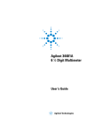
HEWLETT-PACKARD • HP 3478A Digital Multimeter Service Manual 78A SECTION III OPERATION 3-1. INTRODUCTION ric ruish ver -18 the 3-2. This section has the information and instructions for the operation of the 3478A Multimeter, showing front panel and remote operation. The information is an abbreviated description of the operation and is written for a Service Trained Person, rather than an Operator. For more complete operating instructions, refer to the 3478A's Operators Manual. To familiarize yourself with the front and rear panel features or for a review of instrument operations, refer to Figure 3-1. 3-3. The Operation Section is separated into the following major areas: General Information, Front Panel Operation, Shifted Operation, Miscellaneous Operation, and Remote Operation (HP-IB). It is suggested that you read the Remote Operation Chapters last, since you need to know the other operations to understand the remote operations. The major areas are as follows: Title General 3478A Response to Bus Messages 3478A Addressing Talk-Only Mode (No Controller) 3478A HP-IB Programming Advanced programming Paragraph 3-70 3-74 3-92 3-96 3-98 3-117 3·4. GENERAL INFORMATION 3·5. AC Power Operation 3-6. Before connecting ac power to the 3478A, make sure the power source matches the power requirement of the multimeter (as marked on the rear panel). If the instrument is incompatible with the power source, refer to Section II of this manual for power requirement modification. a. General Information - paragraph 3-4. 3·7. Turn·On acind a tal D- Title AC Power Operation Turn-On Display Input Terminals Input Terminals Cleaning Paragraph 3-5 3-7 3-10 3-12 3-15 b. Front Panel Operation - paragraph 3-17. Title Paragraph DC Volts Measurements 3-18 AC Volts Measurements 3-22 Resistance Measurements 3-26 DC Current Measurements 3-30 AC Current Measurements 3-34 Ranging 3-38 3-43 Triggering c. Shifted Operation - paragraph 3-50. Title Paragraph General 3-51 Number Of Digits Displayed 3-54 Autozero 3-57 Self-Test/Reset Operation 3-60 Calibration 3-63 d. Miscellaneous Operation - paragraph 3-66. Title Paragraph Voltmeter Complete 3-67 e. Remote Operation - paragraph 3-69. 3-8. When the 3478A is first turned on, the multimeter goes through an Internal Test routine. During the test, the instrument displays "SELF TEST" and, when the test is completed and it passes, the instrument displays "SELF TEST OK". If the Self-Test fails, refer to Section VII of this manual for troubleshooting information. For more information on the Self-Test, refer to paragraph 3-60. NOTE For 3478As with serial numbers 2301A03760 and below or any instruments that have the Revision B ROM (U502) installed, the instrument displays its remote (HP-IB) addressjor about one second instead oj "SELF TEST OK". The address is displayed as "HPIB ADRS,dd", where "dd" is the address code oj the instrument. 3-9. Once the Self-Test is completed, the 3478A goes to its turn-on state which is: FUNCTION DCV RANGE AUTO TRIGGER INTERNAL AUTOZERO ON NUMBER OF DIGITS DISPLAYED .. 5 3-10. Display 3-11. The Display is a 12 character alphanumeric Liquid Crystal Display (LCD) with 12 annunciators. The display is normally used to show readings, however, the 3-1 Operation 3478A rr:::i1 3478A DIGlTAL MULTIMETER ~ HEWLETT 'PACKARD !1 SENSE INPUT ~"'c\i '300V;;:; ~DN JI. OFf LINE a -DDrnffiEJDD .-"-----------3 RANGE/~ DIGIT 0 ~~~~ [Q] nSENSE INPUT (4 WIRE) (2 WIRE) ~HI~ @ ADRS CAL [T'R'ILG] WARNING: FOR PROTECTION FROM ELECTRICAL SHOCK POWER CORD GROUND MUST NOT BE DEFEATED. 30fJV~ MAX ~LO~ ALL TERM ±5lIJ0Vpk MAX [Q] RESET B B ------~------ ~[Q][Q]~ 10 TEST/ HE\!4..ETT PACKARD MADE IN USA co. 111111111111 .. 2619A34899 .. HPIB 3A R._ ,,;, "~ CAL ENABLE <D o 3A125DV FUSE «~::::::::::~ [Q] '© EXT TRIG SV MAX VM COMP SV MAX @) @) ..~ONSRQ 1 111 1111 1 t··.:-s~~ 1-5IIiz. --L ~lJe ~ 1; B 100V 120V 220V o • 0 (§) 24~ 0 250mAT - - 125mAT ® [Q] 3478A-3-1 keys are used to select special operating features of the CD Use the measurement keys along the top row to select the CD These 3478A. The blue shift key allows for selecting the "SHIFTED" type of measurement you want to make. CD The 12 character alphanumeric display includes 1 2 dedicated annunciators. The display is read directly in engineering units, i.e., MV for milli-volts, MOHM for Meg-ohm resistance, etc. CD If the blue key is pressed before another key, the function shown above that key is executed. CD These terminals are used for the voltmeter sense leads when making 4-wire ohms measurements. CD These terminals are the voltmeter and 2-wire ohms input, 4-wire ohms source current terminals. CD This is the Amps input terminal and is used with the INPUT LOW terminal. (3 Amp fuse protected) CD When this switch is out, the front panel input terminals are selected. If the switch is in, the rear panel terminals are used. functions of the bottom row of keys. The Internal Triggar is selected by this key. In this mode, the 3478A triggers itself. Autozero is a function that allows you to enable or disable the internal zero correction circuitry. Pressing the Single Trigger key causes the 3478A to take one reading and wait for the next trigger impulse. This impulse can come from either the Single Trigger key or the External Trigger input (rear panel BNC). The Test/Reset key performs an internal self test, then resets the 3478A to its turn-on state. Any errors in the self test are noted in the display. The front panel SRQ (Service Request) key is an HP-IB operation that enables you to manually interrupt the controller. This key is enabled by setting the SRO mask. Figure 3·1. 3478A Front and Rear Panel Features 3-2 3478A 3478A Operation The 347 8A HP-IB Address is displayed when the Address key is pressed. The Local key returns the 34 78A to front panel control from the REMOTE mode. The 3478A features total electronic calibration. The Cal key is used as part of that procedure. See Section IV. CD The range keys are used to select the proper range for the measurement. Press any of the keys to select the manual range mode. Note the M RNG annunciator in the display. The Auto/Man key will return the meter to autorange. @The Rear Input Terminals are only used in the DC Volts, AC Volts, and Ohms Functions. They are selected with the Front/Rear Switch in the "in" position. @The External Trigger connector is used to externally trigger the 3478A, when in the Single Trigger mode. @HP-IB Connector. @The Voltmeter Complete Connector outputs a pulse after each measurement cycle. @ The Fuse is 250mA for the 100V and 120V operation, or 125mA for the 220V and 240V operation. @The Option Label shows the instrument's power option. @The "SHIFTED" functions of the range keys are used to select alternate numbers of display digits. @These switches select the 3478A's HP-IB Address, the PowerOn SRO feature, and correct power line frequency (50Hz-60Hz), Figure 3·1. 3478A Front and Rear Panel Features lcont'dl display can also show alphanumeric messages (sent remotely). The four characters to the right show the function (and to a certain extent, the range) and the 8 characters to the left show the reading (e.g. + 12.3657 MVDC). An "OVLD" is displayed if the input is out of range for the selected range and function. 3·12. Input Terminals n SENSE INPUT ~lrO ""p' ~l~ RSHUNT 3A "AX 3-13. The 3478A has one set of Input Terminals on the front panel and one set on the rear panel. The front panel terminals consist of an "INPUT HI", "INPUT LO", "0 SENSE HI", 0 SENSE LO", and "A" (Amps) terminal. Except for the "A" terminal, the rear panel has the same set of terminals. The two sets of terminals are selected by the Front/Rear Switch (located on the front panel). The front terminals are selected with the switch "out" and the rear with the switch "in" . of the TED" e, the 3-14. The INPUT HI and LO Terminals are used for measuring dc volts, ac volts, and resistance in the 2-Wire Ohms configuration. Refer to Figure 3-2 for a typical connection. The 0 SENSE HI and 0 SENSE LO Terminals (in conjunction with the INPUT Terminals) are used in the 4-Wire Ohms configuration. Refer to Figure 3-4 for a typical ohms connection. The A (Amps) Terminal with the INPUT LO Terminal is used to ,A.LLTERt1 '5110V", ItA, --L II =.W 3A 3A/250V FUSE II DC DR AC CURRENT SOURCE 3478 3-3 Figure 3·3. Typical Current Measurement Connection measure ac or dc current. Refer to Figure 3-3 for a typical current connection. 3·15. Input Terminals Cleaning 3-16. The high input impedance of the 3478A requires that the area surrounding the multimeter's Input Terminals (front or rear) must be free of leakage causing paths (e.g. dirt, fingerprints, etc.). The paths can be removed by using a soft cotton swab dipped in isopropyl alcohol. the in- 3·17. FRONT PANEL OPERATION n SENSE e one e can rigger @l ts the noted ~I pera. This INPUT 3·18. DC Volts Measurements 3-19. The 3478A is able to make dc volts measurements from .luV to 300V in five ranges: 30mV, 300mV, 3V, 30V, and 300V. All ranges are protected from input voltages up to 450V peak. Select the DCV Function for dc volts measurements by pressing the = v button. [QJ~ 1 3A1250V FUSE 3478 3-2 Figure 3·2. Typical Input Measurement Connection 3-20. In the DC Volts Function, ranging is done in the Input Circuitry of the 3478A. The result is that the input to the AID Converter (which changes the voltage to digital information) has the same value in all ranges for 3-3 Operation 3478A all full scale inputs (e.g. 10V input to the AID for 30mV, 3OOmV, 3V, etc. inputs to the 3478A). 3-21. When the DC Volts Function is selected, the right side of the display shows "MVDC" or "VDC", dependent on the range selected. The reading can be displayed either as a 5 1/2, 4 1/2, or 3 1/2 digit reading, dependent on the selected Number Of Digits Displayed (see paragraph 3-54). Refer to Table I-lor Table 4-1 for the DC Volts Function's accuracy specifications. UNKNOWN RESISTANCE Rx 3-22. AC Volts Measurements 3-23. The 3478A uses a True RMS AC to DC Converter to measure ac voltages from 1uV to 300V in four ranges: 3OOmV, 3V, 30V, and 3OOV. The response of the converter is from 20Hz to 100KHz on all ranges (to 300KHz on the 30V Range only). All ranges are protected from input voltages up to 450V peak. Select the AC Volts Function for ac volts measurements by pressing the "- v button. 3-24. The AC to DC Converter changes the ac input voltage to dc volts, which is then measured by the 3478A's AID Converter. All ranging is done in the AC to DC Converter, applying the same voltage value to the AID Converter for all full scale inputs. 3-25. When the AC Volts Function is selected, the right side of the display shows "MVAC" or "VAC", dependent on the range selected. The reading can be displayed either as a 5 Y2, 4 Y2, or 3 Y2 digit reading, dependent on the selected Number of Digits Displayed (see paragraph 3-54.) A .6 second delay is also applied in the ACV Function before a reading is taken (also, during a range change). Refer to Table I-lor Table 4-1 for the AC Volts Function's accuracy specifications. 2-WIRE OHMS MEASUREMENT UNKNOWN RESISTANCE Rx ( TERM 1 3A/2S~V FUSE 4-WIRE OHMS MEASUREMENT 3-26. Resistance Measurements 3-27. The 3478A is able to make resistance measurements from .0001 ohms to 30M ohms in seven ranges. The ranges extend from the 30 ohm to the 30M ohm range. All ranges are protected from input voltages up to 350V peak. Resistance measurements can be made using either the 2-Wire or 4-Wire ohms configuration, which are selected by the 2 WIRE 0 and 4 WIRE 0 buttons, respectively. Refer to Figure 3-4 for the correct ohms connections. 3-28. Resistance measurements are made by applying a known current (generated by the 3478A) to the unknown resistance. The resultant voltage drop is then measured by the 3478A's dc circuitry (Input Circuitry and AID Converter). In the 2-Wire Ohms Function, the voltage drop is measured across the HI and LO INPUT Terminals. In the 4-Wire Ohms Function, the voltage is measured across the HI and LO 0 SENSE Terminals. The Ohms Current Source generates the known current which is applied to the unknown resistance (in both 3-4 Figure 3-4. Ohms Connections ohms functions) from the HI INPUT Terminal. The current values are as follows: Range 30 ohm 300 ohm 3Kohm 30K ohm 300K ohm 3M ohm 30M ohm Current 1mA 1mA 1mA 100uA 10uA 1uA .1uA 3-29. When an Ohms Function is selected, the right side of the display shows either "OHM", "KOHM", or "MOHM", dependent on the range selected. In addition, the "2 0" annunciator is on for the 2-Wire Ohms Function and the "4 0" annunciator is on for the 4-Wire Ohms Function. The ohms reading can be displayed either as a 5 1/2,4112, or 3 1/2 digit reading, 78A 3478A Operation dependent on the selected Number Of Digits Displayed (see paragraph 3-54). A .03 second or a .3 second delay is also applied before each reading in the 3M ohm and 30M ohm Ranges, respectively. Refer to Table I-lor Table 4-1 for the Ohms Function's accuracy specifications. NOTE To insure 4- Wire Ohms accuracy when using long leads, it is suggested to keep the lead resistance as follows: 1. Ohms Sense Lead: < 10K ohms on all ranges 2. Ohms LO Source Lead: < 1/30 ohms of full scale on all ranges. 3. Ohms HI Source Lead: < 1/30 ohms of full scale on the 3K through 30M ohm ranges and < 3K ohms on the 30 and 300 ohms ranges. 3·30. DC Current Measurements 3-31. The 3478A can make dc current measurements from 1uA to 3A in two ranges: 300mA and 3A. The ranges are protected from excessive currents and voltages by a 3A 250V fuse. Select the DC Current Function to measure dc currents by pressing the = A button. 3-32. In the DC Current Function, the current is applied between the INPUT LO and A Terminals. Since a known value resistor (.1 ohm) is connected between the terminals, a voltage proportional to the unknown current and the resistor is generated. This voltage is measured by the 3478A's dc circuitry (Input Circuitry and A/D Converter). he 3-33. When the DC Current Function is selected, the right side of the display shows "MADC" or "ADC", dependent on the range selected. The readings can be displayed either as a 5 Y2, 4 Y2, or 3 Y2 digit reading, depending on the selected Number of Digits Displayed (see paragraph 3-54). Refer to Table I-lor Table 4-1 for the DC Current Function's accuracy specifications. NOTE ide or dims he be g, Current inputs of greater than about 1 amp may cause the current shunt's (.1 ohm Resistor) value to change slightly due to selfheating. This may cause inaccuracies in the measurement. Sufficient time should be allowed for the circuitry to settle after the measurement is complete and before other critical current measurements are made. quency response is from 20Hz to 20KHz. The ranges are protected from excessive currents and voltage by a 3A fuse. Select the AC Current Function to measure ac currents by pressing the "- A button. 3-36. The AC Current Function is similar to the DC Current Function (see paragraph 3-30); a voltage drop across a resistor is measured. The difference is that the resultant ac voltage is changed from ac to dc using the AC to DC Converter. Similar to the AC Volts Function, all ranging is done in the converter. 3-37. When the AC Current Function is selected, the right side of the display shows "MAAC" or "AAC" , dependent on the range selected. The readings can be displayed either as a 5 1/2, 4 1/2, or 3 1/2 digit reading, dependent on the selected Number Of Digits Displayed (see paragraph 3-54). Refer to Table I-lor Table 4-1 for the AC Current Function's accuracy specifications. 3·38. Ranging 3-39. The 3478A has two range modes: Manual and Autorange. Manual ranging is selected by pressing the AUTO/MAN button (if the 3478A is in Autorange) or by pressing either the 0 or 0 buttons. The "M RNG" annunciator on the display then turns on. The following explains the different range modes. 3-40. Uprange. The 3478A upranges to the next higher range each time the 0 button is pressed. The highest selectable range depends on the function selected (e.g. 300V for the AC Volts and DC Volts Functions). If a function is selected with its highest range lower than the previous range, the multimeter defaults to the new highest range. 3-41. Downrange. The 3478A downranges to the next lower range each time the 0 button is pressed. The lowest selectable range depends on the function selected (e.g. 30mV for the DC Volts Function). If a function is selected with its lowest range higher than the previous function, the multimeter defaults to the new lowest range. 3-42. Autorange. The 3478A selects the optimum range when this mode is selected. The mode is selected when the 3478A is first turned on or by pressing the AUTO/MAN button (if in Manual Range). If Autorange is enabled, the 3478A upranges when the reading is at or above ± 303099 and downranges at or below ± 027000 (delete one or two zeroes from the numbers for the 4 1/2 and 3 1/2 Digit modes, respectively). The numeric range points are irrespective of decimal placement. Refer to Figure 3-5 for the autorange points (the example is for the DCV Function; other functions are similar). 3·34. AC Current Measurements 3·43. Triggering 3-35. The 3478A can make ac current measurements from 1uA to 3A in two ranges: 300mA and 3A. The fre- 3-44. The 3478A has three local trigger modes: Internal, Single, and External. In addition to these, a Hold 3-5 3478A Operation range or function, the left portion of the display goes blank (except for the decimal point) until another reading is taken (instrument triggered). 3·50. SHIFTED OPERATION 3·51. General Figure 3·5. Autoranging Points and a Fast trigger mode can be selected, but only over the HP-IB (remote operation). When the multimeter is triggered, the right most digit on the display blinks (showing that the display is updated). The following paragraphs explain the trigger modes. 3-45. Internal Trigger. In this mode, the measurement cycle is internally initiated and the 3478A makes the measurements at the maximum reading rate. The Internal Trigger is selected at instrument turn on or by pressing the INT/TRIO button. 3-46. Single Trigger. In this mode, a measurement cycle is initiated each time the SOL/TRIO button is pressed. When the button is initially depressed, the 3478A initiates a measurement cycle and then places the multimeter in the Single Trigger Mode. If the button is pressed during a measurement cycle (while in the Single Trigger mode), the 3478A starts a new measurement cycle. When the cycle is completed, a new cycle can then be initiated by pressing the Single Trigger button. 3-47. External Trigger. This mode is selected by pressing the SOL/TRIO button and operates the same as the Single Trigger mode. The difference is that the 3478A can be triggered from the External Trigger input on the rear panel. The input is TTL logic compatible and the trigger pulse should be at least lOOnS wide. The 3478A is triggered on the negative edge of the TTL pulse. 3-48. Trigger Hold. In this mode, no triggering is done by the 3478A (no measurement cycle is initiated). This mode can only be selected using the 3478A's remote operation. 3-49. Fast Trigger. This trigger is the same as the Single Trigger except the delays in the ACV and ACI Functions, and high Ohms Ranges are omitted. This trigger can only be selected using the remote operation. NOTE When the 3478A is in the Single Trigger mode and an attempt is made to change 3-6 3-52. The Shifted Operation of the 3478A is used to expand the capabilities of the multimeter using the same number of front panel pushbuttons. This is done by using the bottom row of front panel buttons for two different operations, shifted and unshifted. An unshifted operation (AUTO/MAN, INT/TRIO, etc.) is normally selected by pressing a single button. A shifted operation is done by first pressing the blue "SHIFT" button (on the right end of the upper row of buttons) and then pressing one button (on the lower row). To select a new shifted operation, press the blue Shift button again and the button for the new operation. Table 3-1 lists the shifted operations and corresponding buttons. The shifted operations are also shown in blue lettering above the buttons. 3-53. When the blue Shift button is pressed, the "SHIFT" annunciator on the display is on. The annunciator remains on until a different button is pressed. Table 3·1. Shifted Operations Shifted Operetion Select Button Description Of Operetion 3 Digit (Disp) AUTO/MAN Selects 3 Digits Displayed (see paragraph 3-54). Selects 4 Digits Displayed (see paragraph 3-54). Selects 5 Digits Displayed (see paragraph 3-54l. Turns Autozero on or off (see paragraph 3-571, Places the 3478A into its Internal Test Mode (see paragraph 3-61), Displays the 3478A's current HP-IB Address Code (see paragraph 3-921, Places the 3478A into the calibration mode (see Section IV of this manual). 4 Digit (Disp) 0- 5 Digit (Disp) 0 Az INT/TRIG Test/Reset SGLlTRIG Adffi Cal SRQ LOCAL 3·54. Number Of Digits Displayed 3-55. The 3478A can display readings in either 5 1/2, 4 1/2, or 3 1/2 digits. The 5 1/2, 4 1/2, and 3 1/2 digits can be selected by first pressing the blue Shift button and then either the AUTO/MAN, 0, or 0 button, respectively. 3-56. The Number Of Digits Displayed affects the reading rate of the multimeter. This is because the number of digits determines the integration time of the A/D Converter. In the 4 1/2 digit mode, the integration Operation 3478A exme usifted lly 'on on en ew nd he he rye ~he ~n- r d d d s e time is 1/60 second (or 1/50 second for the 50Hz option), which is called 1 PLC (Power Line Cycle). In the 3 1/2 digit mode, the time is 1/600 second (or 1/500 second for the 50Hz option) which is .1 PLC. In the 5 1/2 digit mode, the 3478A takes 10 readings using the 4 1/2 digit mode and averages them together for an extra digit of resolution. This takes a time of 1/6 second (or 1/5 second in the 50 Hz option) which is 10 PLC. For more information on run-up time and the A/D Converter, refer to this manual's Section VII (Service Group F, A/D Converter theory of operation). 3·57. Autozero 3-58. The Autozero Function of the 3478A is used to compensate for offsets that may be present in the multimeter's internal circuitry (DC/Ohms Input Amplifier, A/D Converter, etc). The method used is to temporarily connect the input of the amplifier to ground (the INPUT LO Terminal) and make a measurement (the INPUT HI Terminal is open at this time). The offset reading is then stored into the 3478A's internal memory. After that, the short is removed and a regular input measurement is made. The offset reading is then subtracted from the input reading and the compensated reading is displayed. Table 3·2. 3478A Error Messages Error Message Definition U.C. RAM FAIL The 3478A has failed its internal RAM self test U.C. ROM FAIL The 3478A has failed its internal ROM self test indicating an error in the ROM CAL RAM FAIL An attempt to write to the Calibration CMOS RAM was unsuccessful UNCALIBRATED The Calibration CMOS RAM has an incorrect checksum showing that calibration is needed A:D LINK FAIL The internal CPU (AID Controller) is unable to communicate with the AID Converter A:D SLOPE ERR The AID Converter is unable to do a proper conversion A:D TEST FAIL The AID Converter has failed its self-test. NOTE 3·63. Calibration 4 ts 3·60. Self·Test/Reset Operation n 3-61. The 3478A uses an Internal Self-Test to check its display and internal circuitry. The multimeter goes through the test at turn-on and also when the Self-Test is selected. The test can be selected by pressing the blue Shift button and then the SGL/TRIG button. When the test is selected from the front panel, all the segments of the display are on except are on as long as the test button is pressed. After that, "SELF TEST" will be n 3-62. If the Self-Test fails, an error message will be displayed indicating the type of failure. If there are multiple failures, only one failure will be displayed. The 3478A then attempts to operate normally (even if a test fails). If another failure is noted while trying to operate normally, the new failure will be displayed. This continues until the test(s) passes or the instrument is taken out of the Self-Test mode. 3-59. The Autozero Function is enabled when the 3478A is turned on and after doing a Self-Test (see paragraph 3-60). The feature can be disabled by pressing the blue Shift button and then the INT/TRIG button. The "AZ OFF" annunciator on the display will light, showing that the function is off. After the function is turned off, the multimeter immediately takes an offset reading and stores it into memory. This last reading is then subtracted from the input measurements that follow. Since no more offset readings are taken, the reading rate of the 3478A is faster (up to twice as fast). If a range, function, or digit change is made, or an attempt is made to calibrate the 3478A, a new offset reading is taken. With Autozero off, the 3478A's input circuitry remains in a static state. This is useful when making measurements in extremely high impedance circuits where the internal switching transients of the 3478A may affect the reading accuracy. The 3478A's long term stability may be affected if the Autozero feature is disabled. e e e displayed during the time of the test. When the test is completed, "SELF TEST OK" will be displayed (if the test passes). The 3478A then resets to its turn-on state (see paragraph 3-9), not the previous state before the test was selected. For 3478As with serial numbers 2301A03760 and below or any instruments that have the Revision B ROM (U502) installed, the instrument turns on all the segments in the display for about five seconds. The display then may show a certain message for about 1/4 second. When the Self-Test is completed, the multimeter's displays its remote (HP-IB) address for about one second. The address is displayed as "HPIB ADRS,dd", where "dd" is the address code of the instrument. 3-64. The 3478A does not have any adjustments to calibrate the instrument; calibration is done electronically. A known good calibration source is applied to the multimeter and the value of the known source is entered into the instrument. A reading is then taken and compared with the value entered. A Calibration Constant is calculated (from the entered value) to correct the reading to the known value, and then stored into memory. The correct readings are calculated using the constants and then displayed. 3-65. There are two steps in calibrating the 3478A. First, the front panel Calibration Switch has to be set to 3-7 3478A Operation CAL/ENABLE. Second, the blue Shift button and the LOCAL (CAL) button have to be pressed for each calibration step (e.g. press the buttons for the DC Volts Function's zero calibration and press the buttons again for the function's full scale calibration). Refer to Section IV of this manual for the calibration procedures. Clear Lockout and Set Local Require Service (SRQ) Status Byte Status Bit Pass Control Abort b. 3478A Addressing (paragraph 3-92) and TalkOnly Mode (paragraph 3-96). NOTE The CAL ENABLE Switch on the front panel should not be in the CALlENABLE position under normal use. It should only be in that position to calibrate the instrument. c. 3478A HP-IB Programming (paragraph 3-98). 3·66. MISCELLANEOUS OPERATIONS 3·67. Voltmeter Complete 3-68. The Voltmeter Complete connector is a BNC connector which outputs a signal at the end of the AID cycle. The signal is a negative going TTL compatible pulse with a time period of approximately IpS. The Voltmeter Complete connector is located on the rear panel. 3-69. REMOTE OPERATION 3-70. General 3-71. The following paragraphs gives device dependent information necessary to remotely operate the 3478A over the Hewlett-Packard Interface Bus (HP-IB). Directions for mechanical interface connections to the HP-IB are given in Section II of this manual. Familiarize yourself with the front panel operation (local) before attempting to use the multimeter in remote (HP-IB). NOTE HP-IB is Hewlett-Packard's implementation of IEEE Std. 488-1978, "Standard Digital Interface for Programmable Instrumentation" and ANSI MC 1.1. 3-72. A general description of the HP-IB is in this manual's Appendix A. Refer to the appendix for any non-3478A related HP-IB information. It is assumed, in the following paragraphs, that you are knowledgeable about the HP-IB. 3-73. The following lists the different 3478A remote operations. a. 3478A Response to Bus Messages (paragraph 3-74). Title Data Trigger (GET) Clear (DCL or SDC) Remote Local Local Lockout 3-8 3-82 3-83 3-85 3-89 3-90 3-91 Paragraph 3-76 3-77 3-78 3-79 3-80 3-81 Title Paragraph General Program Codes Programming the SRQ Mask Clearing Status Register (Status Byte) Power-On SRQ Sending Data to the Display Home Commands Reading Data from the 3478A Front/Rear Switch Position Data Ready Feature Front Panel SRQ Fast Trigger 3-99 3-101 3-103 3-105 3-106 3-107 3-110 3-111 3-113 3-114 3-115 3-116 d. Advanced Programming (paragraph 3-117). Title General Extended Ohms Operation Reading the Binary Status Byte Reading the Error Register Paragraph 3-118 3-119 3-120 3-121 3·74. 3478A Response to Bus Messages 3-75. The following paragraphs explain the 3478A's response to Bus Messages. The multimeter's Bus capabilities are in Table 3-3. Table 3·3. 3478A's Bus Capabilities Mnemonic SH1 AH1 T5 L4 LEO TEO SR1 RL 1 PPO DC1 on CO Interfece Function leme Source Handshake Capability Acceptor Handshake Capability Talker (Basic Talker, Serial poll, Talk Only Mode, Unaddressed to Talk if Addressed to Listen) Listener (Basic Listener, Unaddressed to Listen if Addressed to Talk) No Extended Listener No Extended Talker Service Request Capability Remote/Local Capability with Local Lockout No Parallel Poll Capability Device Clear Capability Device Trigger Capability No Controller Capability 8A alk- Operation 76. Data. The Data Message is used to transfer infor'on between the 3478A and the controller. disabled by the Local Lockout Message, see next paragraph). a. The message is used to send data to the multimeter 3-81. Local Lockout. All the front panel buttons are disabled with this message, if the 3478A is in remote. The message is in effect until cleared over the HP-IB or power is cycled. d consists primarily of set-up information (e.g. DC olts, 30V Range, etc.). The 3478A is the Listener and e controller is the Talker. b. The message is also used by the controller to teeeive data from the 3478A. This includes the Ilultimeter's output (readings) and status information. .In this case, the 3478A is the Talker and the contrqller is the Listener. ~77. Trigger (GET, Group Execute Trigger). The Trigger message causes the 3478A to initiate a measurement cycle. It is an HP-IB Trigger and triggers the multimeter in any trigger mode, since it has priority over the other trigger modes. If the 3478A is triggered during a measurement cycle, the cycle is aborted and a new cycle is initiated. There may be a delay (up to .5 sec) if a cycle is in progress when the trigger is received. The multimeter has to be programmed to "listen" to execute the trigger. 3·78. Clear (DCL or SDC: Device Clear or Selective Device Clear). A Clear places the 3478A into its turn-on routine (see paragraph 3-7). In addition, the multimeter's address switch (see paragraph 3-92) is read and the SRQ Mask is set to zero or octal 200 (if the Power-On SRQ switch is on, see paragraph 3-106). If during the turn-on routine an error is detected, the hardware error bit in the serial poll register is set. 's s 3·79. Remote. The Remote Message allows the 3478A to be controlled over the HP-IB. In remote, the front panel buttons, except the LOCAL and Front Panel SRQ buttons, are disabled. The Local and Front Panel SRQ buttons are only disabled when the 3478A is in remote and local lockout (see paragraph 3-81). The instrument state in remote is determined by the local state before being placed in remote. The RMT annunciator on the display will also be on with the 3478A in remote. 3·80. Local. This message clears the remote operation of the 3478A and enables its front panel operation. Pressing the front panel LOCAL button also places the multimeter in the local state (if the button has not been Power-On SRQ - - - Service Request Bit - - - - - Invalid Calibration _ Front Panel SRQ - - - - - - - - - - - ' 3-82. Clear Lockout and Set Local. This message placed the 3478A into local and the Local Lockout Message is cleared. 3.83. Require Service (SRQ). The Require Service Message (SRQ Message) is independent of all other HPIB activity and is sent on a single line called the SRQ Line. Its state is either true or false (low = true and high = false). The 3478A must be programmed to send the SRQ Message. This is done by programming the SRQ Mask (see paragraph 3-103). The front panel SRQ annunciator is on when the 3478A requires service. 3-84. Since more than one device (on the same Bus) can output the SRQ Message, the devices can be polled by the controller (by a Serial Poll) to determine if the 3478A (or another device) requires service. The 3478A then outputs a Status Byte (see paragraph 3-85) which shows for what reason the muItimeter requires service. 3-85. Status Byte. The Status Byte is output by the 3478A in response to a Serial Poll. The message has the same information as the 3478A's Status Register (see next paragraph), and sets the corresponding bit true for any true SRQ condition shown in Table 3-4 (whether the SRQ Mask is set or not). The bit is represented in Figure 3-6. 3-86. The 3478A can require service if any condition in Table 3-4 is true. Since the SRQ Mask must be set to output the Require Service Message (except for bit 7, which is set by the Power-On SRQ switch), the 3478A's Status Register is used to monitor the conditions. This way, only the condition that is set by the mask outputs the SRQ Message. Other true conditions that can cause an SRQ Message, but which are not set by the SRQ Mask, remain in the Status Register as a true condition. They will not cause the SRQ Message to be output. For example, suppose the Front Panel SRQ condition is the only one set in the SRQ Mask. If the Data Ready condition is true, but not Front Panel SRQ, no SRQ Message - - - - - Data Ready 1-.------ Bit Always 0 '-Syntax Error I - . - - - - - - - - - I n t e r n a l Error Figure 3·6. Status Byte 3-9 Operation 3478A Table 3·4. Status Byte Definitions Oetll Codl Oleiml' Codl 001 Bit Olfinitions o Data Ready - Indicates to the controller that measurement data is ready to be output. The Require Service Message and bit is cleared when the controller begins to accept the data or when the reading is no longer available. See paragraph 3-114. 002 2 1 This bit is always at 0 (0 = high). 004 4 2 Syntax Error - This shows that an invalid Program Code(s) has been sent to the 3478A (e.g. F9). 010 8 3 Internal Error - Shows that a failure in the 3478A is detected. This may be a failure in the Self-Test Routine (see paragraph 3-60), the AID Converter, or a checksum error in the Calibration RAM (checked every time a reading is taken). More information can be obtained by reading the 3478A's error register. See paragraph 3-120. 020 16 4 Front Panel SRO - This bit is set when the 3478A's Front Panel SRO button is pressed. See paragraph 3-115. 040 32 5 Invalid Calibration - When this bit is set, an attempt to calibrate the 3478A has failed. 100 64 6 This is the SRO bit. This bit is true only if a Require Service Message is output. 200 128 7 Power-On SRO - Shows that a power-on reset has occurred. See paragraph 3-106. 3-88. The byte is output as shown in the previous example with the corresponding octal number of the example at 125 shown as follows: 3-89. Status Bit. The 3478A does not respond to a Parallel Poll. The Status Bit is used only for Parallel Poll and should not be confused with the bits in the Status Byte Message. 3-90. Pass Control. The 3478A does not have controller capabilities. 3-91. Abort (Interface Clear). All HP-IB communication is terminated (including the 3478A's Bus communication). Control is returned to the controller. The Abort Message does not remove the 3478A from remote control. 3·92. 3478A Addressing 3-93. HP-IB requires that each device on the Bus needs to be identified as a Listener or a Talker, in order to execute the Bus Messages and commands. Because of this, each device has its own unique "listen" and "talk" address. The address of the 3478A is set by the Address Switch on its rear panel. Setting the 3478A's Listen Address also sets its Talk Address. 3-94. The address switch is an eight section "DIP" switch with five sections used for addressing. The switch is shown in Table 3-5. The allowable address settings are also listed in Table 3-5. The factory address setting of the 3478A is decimal 23 (refer to Section II of this manual for the switch setting). Note: More than one bit in the Status Byte can be true (see paragraph 3-87). is output (the Status Register's Data Ready bit is true). The only way the SRQ Message is output is if the Front Panel SRQ condition is true. 3-87. More than one bit in the Status Byte Message can be true. For example, bit 0, 2, and 4 are true (remember, bit 6 is true for any SRQ condition, if the SRQ Mask is set for the condition) making the resultant Status Byte look like the following: NOTE A H1" in this example shows a true condition. 3-10 3-95. Instrument address commands (sent by the controller) are usually in this form: universal unlisten, device talk, device listen. The universal unlisten command removes all listeners from the Bus to allow only the addressed listener(s) to receive data. The data is sent by a talker which is designated by the device talk command. 3·96. Talk·Only Mode (No Controller) 3-97. The 3478A's Talk-Only Mode allows the multimeter to send measurement data to an external device (like a printer) without a Bus controller. The multimeter is placed into the Talk-Only Mode by setting the five address switches (on the rear panel "DIP" switch) to 1 (set only the five address switches to the up position). Measurement data is then output after each trigger. Function and range settings are selected from the front panel. Operation 3478A Table 3·5. 3478A Address Codes INSTRUMENT ADDRESS ~ MWWl~ 16 4 Shown at Factory Default Address (23). This number is called the Primary Address. 1 oa aIlel the ASCII Code Character Listen Talk SP @ ! A B C D E F G H I J K L M # $ % & + I eds exhis, adress AdIP" itch are of this (J P 1 2 3 Q 4 5 6 7 8 9 < R S T U V W X y Z [ \ J > Address Switches A5 A4 A3 A2 A1 o o 000 0 000 1 00010 0 0 1 1 00100 o o o o o o o o o o o o 1 1 1 1 1 1 1 1 1 1 1 1 1 1 1 0 1 0 0 1 1 1 0 1 1 1 000 0 1 1 1 0 0 0 1 1 1 1 1 1 0 0 0 0 0 0 0 0 1 1 1 1 1 1 1 0 1 1 1 1 0 0 0 0 1 1 1 1 0 0 0 0 1 1 1 1 0 0 1 1 0 0 1 1 0 0 1 1 0 0 1 1 0 0 1 1 0 1 0 1 0 1 0 1 0 1 0 1 0 1 0 1 0 1 0 1 0 5-bit Decimal Code 00 01 02 03 04 05 06 07 08 09 10 11 12 13 14 15 16 17 18 19 20 21 22 23 24 25 26 27 28 29 30 3·98. 3478A Hp·IB Programming on- the nal he ing P" up ach om 3·99. General. The following paragraphs explain how to program the 3478A over the HP-IB. The information is given using the HP-IB format, rather than controller dependent language. If the information is desired using controller dependent language, refer to the 3478A's Operator's Manual. 3-100. Programming the 3478A is done by DATA messages. Set-up information (Range, Function, etc.) is DATA sent by the controller and is done using program codes. The DATA received by the controller (from the 3478A) is measurement data, and other data like the Status Byte and the five bytes from the Output Binary Status Byte. 3·101. Program Codes. All the program codes for the 3478A are listed in Table 3-6. The 3478A must be in "remote" and "listen" to receive the codes (the RMT and LSTN annunciators are on when the 3478A is in remote and listening). An example is as follows: CMD MDDE DATA MDDE 7U7 F1 RA T3 " '. ~:~::~:~~ JI IL S'"gl, Trigg.. controller "talk" address 3478A "listen" address Autorange DeV Function L-- 3-102. The Program Codes are a series of 7-bit ASCII characters (the parity bit is ignored). All lower case characters, spaces, commas, and semicolons are ignored (they may be used with the codes as separators). All null characters, carriage return, line feed, form feed, vertical tab, and horizontal tab characters are also ignored. Other characters which are not included in Table 3-6, cause a Syntax Error (bit 2 in the Status Register set). In addition, a Syntax Error is caused if the characters are sent in a different order than shown in the table (e.g. "IF" causes a Syntax Error). Do not send program codes "w" and/or "X" to the 3478A. These codes can, under certain conditions, uncalibrate the instrument. The letters "w" and "X" can, however, be sent behind program codes "D2" or "D3" (which are used to send text to the display; see paragraph 3-107). 3·103. Programming the SRQ Mask. The SRQ Mask must be set for the 3478A to output a Require Service Message. Setting the SRQ Mask will not set the bits in the Status Byte; these bits are automatically set (except bit 6) when any corresponding require service condition is true. For example, you wish to know if the multimeter has received an incorrect program code (Syntax Error) or has an internal failure (Internal Error). If the conditions are true, bits 2 and 3 of the Status Byte are set; but no Require Service Message is output. The message will not be output until the SRQ Mask is set to the corresponding bits of the Status Byte (which are are bits 2 and 3). Since the mask is to be set in octal, the resultant code for the bits is "14". The mask is set by sending "Mdd", where dd is the octal code for the bits. This is shown in the following example. 7 U 7 M14 ""'."~', """MOO ,omm,"" J II L controller "talk" address 3478A "listen" address set mask (where 14 is the octal code for bits 2 and 3) 3-104. Only bits 0 to 5 can be set by programming the SRQ Mask. Bit 6 of the Status Byte is set whenever the Require Service Message is output and bit 7 is set by the Power-On SRQ switch on the rear panel (see paragraph 3-106). Because of this, only a two digit octal code (00 3-11 Operation 3478A Table 3-6. 3478A Program Codes Type FUNCTION Progrlm Code Description F1 F2 F3 F4 F5 F6 F7 DC Volts AC Volts 2-Wire Ohms 4-Wire Ohms DC Current AC Current Extended Ohms 3-1181. R-3 RA most sensitive range on any function 30m V DC, or most sensitive range on any other function 300mV DC, 300mV AC, 300mA DC, 300mA AC, or most sensitive range on any other function 3V DC, 3V AC, 3A DC, 3A AC, or most sensitive range on any other function 30V DC, 30V AC, 30 Ohm, or most sensitive range on any other function 300V DC, 300V AC, 300 Ohm, or least sensitive range on any other function 3K Ohm or least sensitive range on any other function 30K Ohm or least sensitive range on any other function 300K Ohm or least sensitive range on any other function 3M Ohm or least :;ensitive range on any other function 30M Ohm or least sensitive range on any other function. Autorange DIGITS DISPLAYED N3 N4 N5 3 1/2 Digits Displayed 4 1/2 Digits Displayed 5 1/2 Digits Displayed TRIGGER T1 T2 T3 T4 T5 Internal Trigger External Trigger Single Trigger Hold Trigger Fast Trigger (see paragraph 3-116) AUTOZERO ZO Z1 Autozero Disabled Autozero Enabled DISPLAY 01 02 Normal Display Operation Display Text and update Annunciators Display Text and turn off Annunciators RANGE R-2 R-1 RO R1 R2 R3 R4 R5 R6 R7 03 (see paragraph HOME COMMAND HO H1 H2 H3 H4 H5 H6 H7 Equivalent Equivalent Equivalent Equivalent Equivalent Equivalent Equivalent Equivalent MISC. COMMANDS B Read Status of the 347 8A in Binary. See paragraph 3-1 19. Calibrate (see Section IV of this manual) Read the Error Register. See paragraph 3-120. Clears Status Register Set SRQ Mask (Mdd, where dd is the oc~al code of the bits) Front/Rear Switch Position (0 = Rear, 1 = Front) C E K M S 3-12 77) can be sent to program the mask. The mask can be cleared by sending: "MOO". Remember, the mask is only set to output a Require Service Message (not the Status Byte) for a certain SRQ condition. to to to to to to to to "F1 T4R-2RAZ1 N4" "F1 R-2RAZ1 N4T3" "F2R-2RAZ 1N4T3" "F3R-2RAZ1 N4T3" "F4R-2RAZ1 N4T3" "F5R-2RAZ1 N4T3" "F6R-2RAZ1N4T3" "F7R-2RAZ1 N4T3" 3-105. Clearing Status Register (Status Byte). Bits 2 through 5 and 7 of the register can be cleared by sending program code "K", and by a device CLEAR message. Bit 0 (Data Ready) is not cleared since it represents the 3478A's current status (the bit is cleared when the 3478A outputs its reading). Bit 6 is the SRQ bit which can be cleared by a Serial Poll or if the SRQ Mask is set to 00. 3-106. Power-On SRQ. This feature is enabled by setting the Power-On SRQ switch to On (switch #3 on the rear panel in the up position). When the feature is enabled, the 3478A Requires Service (generates an SRQ) each time power is cycled or a reset condition is generated by the instrument (e.g. due to an instrument failure or selecting the Self-Test). 3-107. Sending Data to the Display. Up to 12 ASCII characters can be displayed at a time by the 3478A's display. The legal characters are decimal 32 through 95 of the 128 ASCII characters. Only upper case letters and numbers can be displayed. Lower case letters generate characters which do not resemble the letters. Commas, periods, and semicolons can go between characters. The ASCII characters can be sent in two different modes. The following paragraphs explain the two modes. 3-108. In one display mode, the display is continuously updated. This is enabled by program code "D2" (e.g. "D23478A DMM" where "3478A DMM" is the message displayed). In this mode, the annunciators continue to be updated. If more than 12 characters are sent to the display, the extra characters are ignored until a control character is received. If the control character is different than HT (Horizontal Tab), VT (Vertical Tab), LF (Line Field), CR (Carriage Return), or FF (Form Feed), a Syntax Error is generated. A "D2" code locks the display until a "Dl" (Selects Normal Display) is sent, a CLEAR message is sent, an error condition occurs, or a front panel button is pressed. 3-109. The other display mode is selected by sending code "D3". This mode is the same as the previous mode, except the display is not updated and all annunciators are turned off. The text on the display remains on for about 10 minutes and then the display goes blank. The display can be restored by sending any of the display codes (Dl, D2, or D3) or by pressing the LOCAL button (if not disabled by the LOCAL LOCKOUT Message). 3-110. Home Commands. The Home Commands (when sent to the 3478A over the HP-IB) are used to set the 3478A into a predefined operating state. The program code is "Hn", where n is the number which 8A 3478A be defines the state. The following lists the home commands and the corresponding operating states. a. HO Command. The instrument state for this command is as follows: Function...................... DCV (FI) Range......................... 30mV, Auto (R-2RA) Trigger....................... Hold (T4) Number of Digits Displayed.... 4 1/2 (N4) Autozero...................... On (Zl) In addition, the 3478A's External Trigger is disabled and the instrument is set into the lowest range (R-2) before Autorange is selected. Also, any data (reading) output to the Bus or the front panel is erased when the home command is sent. The corresponding program codes of the instrument state are: "FIT4R-2RAZIN4". n .'s ~5 ld le 15, ~e 5. Iy g. le ~ nt !a is ~, ~ ~- b. HI Command (DCV). This command is the same as the "HO"command, except a trigger occurs and the resultant output can be read. The corresponding program codes are: "FIR-2RAZIN4T3". c. H2 Command (ACV). The same as the "HI" command, except the selected function is AC Volts. The corresponding program codes are: "F2R-2RAZIN4T3" . d. H3 Command (2-Wire Ohms). Same as the "HI" command, except the selected function is 2-Wire Ohms. The corresponding program codes are: "F3R-2RAZIN4T3" . e. H4 Command (4- Wire Ohms). Same as the "HI" command, except the selected function is 4-Wire Ohms. The corresponding program codes are: "F4R-2RAZIN4T3" . f. H5 Command (DCI). Same as the "HI" command, except the selected function is DC Current. The corresponding program codes are: "F5R-2RAZIN4T3" . s g. H6 Command (ACI). Same as the "HI" command, except the selected function is AC Current. The corresponding program 'codes are: "F6R-2RAZIN4T3" . s s e e h. H7 Command (Ext. Ohms). Same as the "HI "command, except the selected function is Extended Ohms (see paragraph 3-119). The corresponding program codes are: "F7R-2RAZIN4T3" . I g 3-111. Reading Data from the 3478A. Data in the form s t of readings can be output by the 3478A over the HP-IB (other data that can be output is discussed in later paragraphs). To output a reading (if available), the 3478A has to be addressed to "talk". The readings are output using 13 ASCII characters and are in the following form:. Operation ~D.DDDDDE ± Polarity of reading (a" +" is sent for ac readings) D CR LF(EOIl .-J~ Reading expressed in scientific notation (D is a decimal digit) Carriage Return Line Feed (with End or Identify Line set) -1 3-112. Each character in the output statement (except EOI) is one byte, which adds up to 13. The exponent will be in engineering notation (E-3, E + 0, E + 3, or E + 6) and the mantissa will always have I, 2, or 3 digits before the decimal point (D.DDDDD, DD.DDDD, or DDD.DDD). If the 3478A is in the 4 1/2 or 3 1/2 Digit mode, the 5th and/or 6th digits will be output as zeroes. An overload condition (whether plus or minus) will be output as: + 9.99999E + 9. If a different output is requested (Binary, Front/Rear Switch position, etc.), the other output supercedes the reading. If a data transfer is interrupted while being output, the 3478A continues the output wherever it left off, when addressed again. This partial output (or any output) can be disabled by a Group Execute Trigger (GET), Clear Message (DCL or SDC), sending any valid program code, or pressing the LOCAL, Shift, and TEST/RESET buttons on the front panel. 3-113. Front/Rear Switch Position. The 3478A's Front/Rear Switch position can be remotely determined by sending program code "S" to the multimeter and then reading its output. If "0" (CR LF) is output the switch is set to Rear, and if "I" (CR LF) is output the switch is set to Front. 3-114. Data Ready Feature. The Data Ready feature of the 3478A, when enabled, outputs a Require Service Message (SRQ) after each completed measurement cycle. Before the message can be output, bit 0 of the SRQ Mask must be set. This is done by sending program code "MOl" (bit 0 of the Status Byte and Status Register). When the Require Service Message is sent, the front panel "SRQ" annunciator turns on and bit 0 of the Status Byte is set. The SRQ condition remains until the data is read by the controller, or a Serial Poll is done. 3-115. Front Panel SRQ. The Front Panel SRQ feature of the 3478A outputs a Require Service Message (SRQ) each time the Front Panel SRQ button is pressed. Before the message can be output, bit 4 of the SRQ Mask must be set. This is done by sending program code "M20" (bit 4 of the Status Byte and Status Register). Once this is done, the Require Service Message will be output and the front panel SRQ annunciator turns on, whenever the SRQ button is pressed. The SRQ condition remains until a Serial Poll is done by the controller. 3-13 Operation 3478A 3-116. Fast Trigger. This trigger mode can only be selected over the HP-IB. It is the same as the Single Trigger, except the delays in the AC Volts Function, AC Current Function, and the high Ohms Ranges are omitted. The mode can be selected by sending program codes "T5" . Table 3·7. Binary Status Byte Definition Byte # Bits True XXXXXX01 XXXXXX10 XXXXXX11 XXX001XX 3·117. Advanced Programming 3-118. General. The following paragraphs have advanced programming information for the 3478A. It includes Extended Ohms Operation, Reading the Binary Status Byte, and Reading the Error Register. 3-119. Extended Ohms Operation. This operation (or function) is only available over the HP-IB and is used to measure resistance above 30M ohm. The function is selected by sending program code "F7" or "H7" (Home Command, see paragraph 3-110). The 3478A is set to the 2-Wire Ohms Function and the 30M ohm Range. A 10M ohm resistor is connected in parallel with the input. Measure the resistance first and then measure the unknown resistance. The unknown resistance can then be calculated by this formula: XXX010XX XXX011XX XXX100XX XXX101XX XXX110XX XXX1 11XX 001XXXXX 010XXXXX 011XXXXX 100XXXXX 101XXXXX 110XXXXX 111XXXXX 2 1 2 3 4 5 6 7 3 1 2 3 4 5 6 7 10 OUTPUT 723 ;"B" 20 ENTER 723 USING "5(1B)" ;Bl,B2,B3,B4,B5 3-121. Reading the Error Register. Besides using Binary Status Byte 4 (see previous paragraph), the status of the Error Register can also be determined by sending program code "E" to the 3478A and then reading its output. The output is a two digit octal number followed by a carriage return and line feed. The number shows which bit(s) of the register is true (a two digit number can be used since only 6 bits are used by the register). For example, bits 0 and 5 are true which results in octal "41" (the maximum value is "77")~ Refer to Table 3-7 (byte 4) for the definitions of the bits. The Error Register is also cleared by sending program code "E". 3-14 Bit# = 1 o 3-120. Reading the Binary Status Byte. The current status (or state) of the 3478A can be determined by reading its Binary Status Byte. The total number of bytes is five, with each byte 8 bits wide. The bytes can be read by sending program code "B" to the 3478A and then reading its output. A small program to read the output using the -hp- Model 85 Personal Computer is as follows: The bytes are in variables Bl, B2, B3, B4, and B5. The bytes and corresponding meanings of the bits (when true) are in Table 3-7. Program Code "B" clears the Error Register (byte 4; see Table 3-7). Bit#= 1 o Ri * Rt Rx = - - Ri - Rt where Rx is the unknown resistance, Ri is the measured 10M ohm resistor, and Rt is the measured value of the parallel combination. Definition 4 Bit# = 1 o 1 2 3 4 5 6 7 5 Function, Range, and Number Of Digits Displayed 5 112 Digits Displayed 4 112 Digits Displayed 3 112 Digits Displayed 30mV DC, 300mV AC, 30 Ohm, 300mA AC or DC, or Extended Ohms Ranges 300mV DC, 3V AC, 300 Ohm, 3A AC or DC Ranges 3V DC, 30V AC, 3K Ohm Ranges 30V DC, 300V AC, 30K Ohm Ranges 300V DC, 300K Ohm Ranges 3M Ohm Range 30M Ohm Range DC Volts Function AC Volts Function 2-Wire Ohms Function 4-Wire Ohms Function DC Current Function AC Current Function Extended Ohms Function Instrument Status Bits Internal Trigger Enabled Autorange Enahled Autozero Enabled 3478A set for 50Hz Operation Front/Rear Switch in Front Position Calibration RAM Enabled External Trigger Enabled Always Zero (not true) SRQ Mask Data Ready - SRQ for every available reading to the HP-IB Not used Syntax Error - SRQ if Syntax Error occurs Internal Error - SRQ if Hardware Error occurs Front Panel SRQ - SRQ if SRQ button is pressed Calibration Error - SRQ if CAL procedure failed Always Zero (not true) Power-On SRQ - PON SRQ switch on last time power was turned on or DCl message was received Internal Error Information Set if any of the Calibration RAM locations have incorrect checksums or if a range with an incorrect checksum is selected The Main CPU RAM Self-Test has failed The Control ROM Self-Test has failed An AID Slope Error was detected The AID has failed its Internal Self-Test A failure in the AID link (between U403 and U462) Always Zero Always Zero Bits AID DAC Value 0-7 A decimal value between 0 to 63 represents the setting of the internal Digital to Analog Converter (DAC). (Refer to this manual's Section VII for